1. نظرة عامة على المنتج
تمثل سلسلة ELM8XL-G عائلة من مقومات الضوء (العوازل الضوئية) ذات مخرج البوابة المنطقية عالية السرعة، المصممة لتطبيقات العزل الرقمي الحديثة. الوظيفة الأساسية لهذا الجهاز هي توفير عزل كهربائي كامل بين دوائر الإدخال والإخراج أثناء نقل إشارات المنطق الرقمي بسرعات عالية. فهو يدمج ثنائي باعث للضوء بالأشعة تحت الحمراء (LED) على جانب الإدخال، والذي يكون مقترنًا ضوئيًا بدائرة متكاملة لكاشف CMOS على جانب الإخراج. تزيل طريقة الاقتران الضوئي هذه الاتصال الكهربائي، مما يوفر عزلًا عالي الجهد ومناعة ضد الضوضاء، وهو أمر بالغ الأهمية في الأنظمة ذات جهود التأريض المختلفة أو في البيئات الكهربائية ذات الضوضاء.
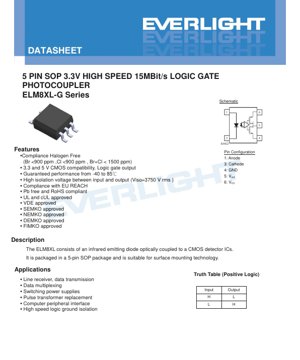
يتم تغليف الجهاز في حزمة سطحية صغيرة الحجم من نوع SOP ذات 5 أطراف، مما يجعله مناسبًا لعمليات التجميع الآلي وتصاميم لوحات الدوائر المطبوعة (PCB) المحدودة المساحة. هدفه التصميمي الأساسي هو تسهيل نقل البيانات الموثوق عالي السرعة عبر حواجز العزل، ليكون بديلاً مباشرًا لمحولات النبض في العديد من التطبيقات مع تقديم مزايا في الحجم والتكلفة والتكامل.
1.1 المزايا الأساسية والسوق المستهدف
تقدم سلسلة ELM8XL-G عدة مزايا رئيسية تحدد موقعها في السوق. أولها هو القدرة عالية السرعة، حيث يدعم معدلات بيانات تصل إلى 15 ميغابت في الثانية (MBit/s). وهذا يجعله مناسبًا لواجهات الاتصالات الحديثة وإشارات التحكم السريعة. ثانيًا هو التوافق مع جهدي تغذية مزدوجين، حيث يعمل بشكل صحيح مع مستويات منطق CMOS بقيمة 3.3 فولت و5 فولت، مما يوفر مرونة في التصميم للأنظمة ذات الفولتية المختلطة. ثالثًا هو تصنيف عزل عالي بقيمة 3750 فولتجذر متوسط مربعضمان السلامة والموثوقية في التطبيقات التي تتطلب الحماية من الارتفاعات المفاجئة للجهد العالي أو الاختلافات في جهد التأريض.
يتم تصنيع الجهاز أيضًا ليلبي معايير بيئية وأمان صارمة. وهو خالٍ من الهالوجين (with Bromine <900ppm, Chlorine <900ppm, Br+Cl <1500ppm), compliant with EU REACH regulations, and is both Pb-free and RoHS compliant. It carries approvals from major international safety agencies including UL, cUL, VDE, SEMKO, NEMKO, DEMKO, and FIMKO, which is essential for products targeting global markets, particularly in industrial, telecommunications, and computing equipment.
التطبيقات المستهدفة متنوعة وتركز حول الحاجة إلى عزل الإشارة:
- مستقبلات الخطوط ونقل البيانات: عزل خطوط الاتصال التسلسلي (RS-232, RS-485، إلخ) لمنع حلقات التأريض والضوضاء.
- تعدد إرسال البيانات: توفير العزل في أنظمة ناقل البيانات المتعددة.
- مصادر طاقة التبديل: عزل إشارات التغذية الراجعة في دوائر flyback أو غيرها من التبولوجيات المعزولة للمحولات.
- استبدال محول النبض: تقديم حل أصغر وأكثر تكاملاً لعزل الإشارات الذي كان يُنفذ تقليدياً باستخدام المحولات.
- واجهات أجهزة الطرفيات الحاسوبية: عزل الإشارات من وإلى الطابعات، ووحدات الإدخال/الإخراج الصناعية، والأجهزة الطرفية الأخرى.
- High-Speed Logic Ground Isolation: فصل المسارات الأرضية الرقمية بين الأنظمة الفرعية، مثل تلك الموجودة بين المتحكم الدقيق ووحدات تشغيل المحركات، لمنع اقتران الضوضاء.
2. تحليل متعمق للمعايير التقنية
إن الفهم الشامل للخصائص الكهربائية وخصائص التبديل أمر بالغ الأهمية لتنفيذ ناجح لعازل الضوء ELM8XL-G في تصميم الدائرة.
2.1 Absolute Maximum Ratings
تحدد هذه التصنيفات حدود الإجهاد التي إذا تجاوزتها قد يحدث تلف دائم للجهاز. لا يتم ضمان التشغيل تحت هذه الظروف ويجب تجنبه.
- تيار الدخل الأمامي (IF): 15 مللي أمبير كحد أقصى. يجب ألا يتجاوز التيار الذي يقود الصمام الثنائي الباعث للضوء الداخلي هذه القيمة.
- جهد عكسي للإدخال (VR): 5 فولت كحد أقصى. يجب تحديد الجهد العكسي المطبق عبر الصمام الثنائي الباعث للضوء.
- تبديد طاقة الإدخال (PD): 35 ميلي واط كحد أقصى لجانب الإدخال.
- استهلاك طاقة الخرج (PO): 85 ميغاواط كحد أقصى لدائرة CMOS المتكاملة للخرج.
- تيار الخرج (IO): 20 مللي أمبير كحد أقصى لتيار المصدر/الاستنزاف من طرفية الخرج.
- جهد التغذية (VCC): 5.5 فولت كحد أقصى. هذا هو الحد الأقصى المطلق للجهد الذي يمكن تطبيقه على دبوس الطاقة في جانب الإخراج.
- Total Power Dissipation (PT): 100 ميغاواط كحد أقصى للجهاز بأكمله.
- جهد العزل (فولتISO): 3750 فولتجذر متوسط مربع for 1 minute. This is a safety rating tested under specific conditions (pins 1 & 3 shorted, pins 4, 5 & 6 shorted) at 40-60% relative humidity.
- درجة حرارة التشغيل (TOPR): من -40°C إلى +85°C. الجهاز مضمون لتلبية مواصفاته المنشورة ضمن هذا النطاق.
- درجة حرارة التخزين (TSTG): -55°C إلى +125°C.
- درجة حرارة اللحام (TSOL): 260 درجة مئوية لمدة 10 ثوانٍ، متوافقة مع ملفات إعادة التدفق الخالية من الرصاص النموذجية.
Design Note: يحدد ورقة البيانات أنه يجب تجاوز مصدر VCC باستخدام مكثف سعته 0.1 ميكروفاراد أو أكبر (سيراميك أو تانتالوم صلب ذو خصائص تردد عالي جيدة) يوضع بأقرب ما يمكن من دبابيس VCC و GND الخاصة بالجهاز. هذا أمر بالغ الأهمية للتشغيل المستقر ومقاومة الضوضاء لمرحلة الخرج عالية السرعة CMOS.
2.2 الخصائص الكهربائية
تحدد هذه المعلمات الأداء المضمون للجهاز تحت ظروف التشغيل العادية (TA=25°C ما لم يُذكر خلاف ذلك).
2.2.1 خصائص الإدخال (جانب LED)
- Forward Voltage (VF): Typically 1.4V, with a maximum of 1.8V at a forward current (IF) of 8mA. This is used to calculate the required current-limiting resistor value on the input side: Rlimit = (Vsupply - VF) / IF.
- الجهد العكسي (VR): 5.0 فولت كحد أدنى. يمكن للصمام الثنائي الباعث للضوء تحمل ما يصل إلى 5 فولت في حالة الانحياز العكسي.
- معامل درجة حرارة VF (ΔVF/ΔTA): تقريبًا -1.7 مللي فولت/درجة مئوية. ينخفض جهد التشغيل الأمامي قليلاً مع زيادة درجة الحرارة.
- سعة الإدخال (CIN): عادةً 60 بيكوفاراد. يؤثر هذا على استجابة دائرة القيادة المدخلة للترددات العالية.
2.2.2 خصائص الإخراج (جانب الدائرة المتكاملة CMOS)
- تيار التغذية (ICCHأناCCL): عادةً 1.3 مللي أمبير، بحد أقصى 6 مللي أمبير، سواء كان الخرج في حالة عالية (IF=0 مللي أمبير) أو منخفضة (IFالحالة (=8 مللي أمبير). هذا هو تيار السكون المسحوب بواسطة دائرة الخرج المتكاملة من مصدر V.CC.
- جهد الخرج عند المستوى العالي (VOH): بالنسبة لمصدر جهد 3.3 فولت، فإن VOH مضمون أن يكون على الأقل VCC - 1V (أي 2.3V) وعادةً ما يكون VCC - 0.3V (3.0V) عند سحب تيار 4mA. بالنسبة لمصدر جهد 5V، فهو VCC - 1 فولت (4.0 فولت) كحد أدنى، عادةً VCC - 0.2 فولت (4.8 فولت). وهذا يضمن مستويات منطقية عالية ثابتة.
- جهد الخرج المنخفض المستوى (VOL): بالنسبة لمصدر جهد 3.3 فولت، فإن VOL عادةً ما يكون 0.21 فولت بحد أقصى 0.6 فولت عند توفير تيار 4 مللي أمبير (IF=8 مللي أمبير). بالنسبة لمصدر 5 فولت، يكون عادةً 0.17 فولت، بحد أقصى 0.6 فولت. وهذا يضمن مستويات منطقية منخفضة ثابتة.
- تيار عتبة الإدخال (IFT): التيار المطلوب لـ LED لضمان خرج منطقي منخفض. عادةً ما يكون 2.5 مللي أمبير (بحد أقصى 5 مللي أمبير) عند VCC=3.3 فولت مع حمل خفيف جدًا (IOL=20 ميكرو أمبير). يجب أن يستخدم التصميم IF أعلى بكثير من هذا (مثل 8 مللي أمبير كما هو موضح في ظروف الاختبار) للتبديل الموثوق بهامش ضوضاء.
2.3 خصائص التبديل
تحدد هذه المعايير أداء التوقيت، وهو أمر بالغ الأهمية لنقل البيانات عالي السرعة.
- تأخر الانتشار إلى الخرج المرتفع (tPHL): الوقت من إطفاء مؤشر LED للإدخال (IF الانتقال من 8mA إلى 0mA) حتى وصول المخرج إلى مستوى منطقي عالٍ صالح. القيمة النموذجية هي 30ns (بحد أقصى 65ns) عند VCC=3.3V، والقيمة النموذجية 33ns عند VCC=5V.
- زمن التأخير في الانتشار للخرج المنخفض (tPLH): الوقت من لحظة تشغيل LED المدخل (IF الانتقال من 0 مللي أمبير إلى 8 مللي أمبير) حتى يصل المخرج إلى مستوى منطقي منخفض صالح. القيمة النموذجية هي 48 نانوثانية (الحد الأقصى 65 نانوثانية) عند VCC=3.3 فولت، و 52 نانوثانية نموذجية عند VCC=5V.
- تشوه عرض النبضة (|tPHL – tPLH|): الفرق المطلق بين زمني التأخير في الانتشار. هذا أمر بالغ الأهمية للحفاظ على سلامة عرض النبضات. عادةً ما يكون 20 نانوثانية (بحد أقصى 50 نانوثانية) عند جهد 3.3 فولت، وعادةً 22 نانوثانية عند جهد 5 فولت. كلما كانت القيمة أقل كان ذلك أفضل.
- زمن الصعود/الهبوط للإخراج (tr، tf): عادةً 7 نانوثانية لكل منهما. هذا يحدد سرعة حافة إشارة الخرج.
- مناعة العبور المشترك (CMTI): هذه معلمة عزل رئيسية. تقيس قدرة الجهاز على تجاهل العابر السريع للجهد بين أرضيات الإدخال والإخراج. يتم تحديد درجتين: M80L بحد أدنى 5,000 فولت/ميكروثانية، وM81L بحد أدنى 10,000 فولت/ميكروثانية. يتم اختبار هذا بجهد مشترك ذروة إلى ذروة 1000 فولت (VCM) ويضمن عدم تبديل حالة الخرج خطأً بسبب الضوضاء.
3. المعلومات الميكانيكية وطريقة التغليف
3.1 توزيع الأطراف وجدول الحقيقة
يستخدم الجهاز حزمة SOP ذات 5 أطراف، على الرغم من الإشارة إلى ستة أرقام للأطراف (1-6، حيث يُرجح أن الطرف 2 هو No Connect أو وصلة داخلية). الأطراف الوظيفية هي:
- الطرف 1: الأنود لليد الداخلي للإدخال.
- الطرف 3: الكاثود لليد الداخلي للإدخال.
- الطرف 4: الأرضي لدارة CMOS الإخراجية المتكاملة.
- الطرف 5: Vخارج، إشارة الخرج الرقمية.
- الطرف 6: VCC، جهد التغذية (3.3V أو 5V) لدارة CMOS IC الخاصة بالخرج.
يُنفِّذ الجهاز بوابة منطقية غير عاكسة وظيفة (منطق موجب):
- إدخال مرتفع (مصباح LED مضاء، IF > IFT): الإخراج = منخفض
- الإدخال منخفض (مصباح LED مطفأ، أناF = 0): الإخراج = مرتفع
هذا إدخال يستنزف التيار؛ يجب توجيه تيار إلى الصمام الثنائي الباعث للضوء لإنتاج خرج منخفض.
3.2 Package Dimensions and PCB Layout
تقدم ورقة البيانات رسومات ميكانيكية مفصلة لحزمة 5-pin SOP. تشمل الأبعاد الرئيسية حجم الجسم، وتباعد الأطراف، وارتفاع التعليق. التخطيط المقترح للوسادة يتم توفيره أيضًا للتركيب السطحي. تم تصميم هذا التخطيط لضمان تكوين موثوق لوصلات اللحام أثناء عملية اللحام بإعادة الانصهار. تشير ورقة البيانات إلى أن أبعاد الوسادة هذه هي اقتراحات وقد تحتاج إلى تعديل بناءً على عمليات تصنيع لوحات الدوائر المطبوعة المحددة أو متطلبات الحرارة، ولكنها تخدم كنقطة انطلاق ممتازة للتصميم.
3.3 Device Marking
يتم تمييز الجزء العلوي من العبوة برمز ليزر أو حبر للتعريف. يتبع الترميز التنسيق التالي: EL M81L YWW V.
- EL: رمز الشركة المصنعة.
- M81L: رقم الجهاز (خاص بدرجة CMTI ومتغيرها).
- Y: رمز السنة المكون من رقم واحد.
- WW: رمز الأسبوع المكون من رقمين.
- V: علامة اختيارية تشير إلى موافقة VDE.
4. إرشادات التطبيق والاعتبارات التصميمية
4.1 تصميم دائرة الإدخال
يجب أن توفر دائرة الإدخال تيارًا مضبوطًا لـ LED. مقاومة متسلسلة بسيطة كافية. يتم حساب القيمة بناءً على جهد التشغيل والتيار المطلوب IF. على سبيل المثال، لتشغيل IF = 8mA من إشارة منطقية 5V مع جهد تشغيل نموذجي VF من 1.4 فولت: Rlimit = (5V - 1.4V) / 0.008A = 450Ω. سيكون المقاوم القياسي 470Ω مناسبًا. تأكد من أن مصدر القيادة يمكنه توفير التيار اللازم. للقيادة من دبوس GPIO لوحدة التحكم الدقيقة، تحقق من قدرة دبوس على توفير التيار. إذا كان غير كافٍ، فقد يلزم وجود عازل ترانزستور بسيط (مثل ترانزستور NPN أو MOSFET بقناة N).
4.2 تصميم دائرة الخرج
الإخراج هو إخراج رقمي قياسي من نوع CMOS. يمكنه تشغيل مدخلات CMOS أو TTL أو LVCMOS مباشرة. المتطلبات الرئيسية هي:
- تجاوز مصدر الطاقة: كما تم التأكيد عليه في ورقة البيانات، يجب وضع مكثف سيراميكي سعة 0.1 ميكروفاراد مباشرة بين الرقم 6 (VCC) والطرف 4 (الأرضي). هذا شرط غير قابل للتفاوض لضمان تشغيل مستقر عالي السرعة ومنع الضوضاء على الخرج.
- اعتبارات الحمل: يمكن للخرج استيعاب/توفير تيار يصل إلى 20 مللي أمبير، ولكن للحصول على أفضل سرعة وسلامة للإشارة، يجب أن تكون الأحمال في الأساس سعوية (مثل السعة الدخلية لبوابة أخرى). تحميل مقاومات ثقيلة أو مسارات طويلة سيزيد من أوقات الصعود/الهبوط وقد يؤثر على هوامش التوقيت.
- مقاومات السحب لأعلى: غير مطلوبة، لأن المخرج يقود بنشاط كل من الحالتين العالية والمنخفضة.
4.3 اعتبارات السرعة والتوقيت
لمعدل بيانات يبلغ 15 ميجابت/ثانية، تكون فترة البت حوالي 66.7 نانوثانية. إجمالي تأخر الإشارة عبر مقرن الضوء هو مجموع tPLH أو tPHL بالإضافة إلى جزء من وقت الصعود/الهبوط. مع تأخيرات نموذجية تتراوح حول 30-50 نانوثانية، هناك هامش كافٍ لمعدل البيانات هذا. ومع ذلك، فإن تشويه عرض النبضة إنه أمر مهم. تشوه قدره 20 نانوثانية يعني أن النبضة ستضيق أو تتسع بهذا المقدار بعد مرورها عبر العازل. بالنسبة للنبضات الضيقة جدًا، قد يؤدي ذلك إلى اختفائها إذا كان التشوه أكبر من عرض النبضة. ضع دائمًا في الاعتبار القيم القصوى، وليس النموذجية، للتصميمات الحساسة للتوقيت.
4.4 Isolation and Safety Design
The 3750Vجذر متوسط مربع تصنيف العزل هو متطلب أمان. للحفاظ على هذا التصنيف في المنتج النهائي، فإن تخطيط اللوحة المطبوعة أمر بالغ الأهمية. تأكد من أن مسافة الزحف والفراغ المسافات على اللوحة المطبوعة بين جميع المسارات/المكونات في جانب الإدخال والمسارات/المكونات في جانب الإخراج تلبي أو تتجاوز متطلبات جهد العزل التشغيلي للنظام (وهو أقل من 3750 فولتجذر متوسط مربع جهد الاختبار). غالبًا ما يعني ذلك دمج فتحة واسعة أو حاجز في اللوحة المطبوعة أسفل حزمة العازل الضوئي. استشر معايير السلامة ذات الصلة (مثل IEC 60950، IEC 61010) للحصول على متطلبات المسافة المحددة بناءً على الجهد، ودرجة التلوث، ومجموعة المواد.
5. معلومات الطلب والتعبئة والتغليف
يتبع رقم القطعة الهيكل التالي: ELM8XL(Z)-V.
- ELM8XL: رقم الجزء الأساسي.
- (Z): خيار الشريط والبكرة. يمكن أن يكون "TA" أو "TB"، أو يُحذف في حالة التعبئة في أنبوب.
- -V: لاحقة اختيارية تشير إلى تضمين موافقة VDE.
خيارات التعبئة والتغليف:
- أنبوب: 100 وحدة لكل أنبوب. معيار للتجميع اليدوي أو منخفض الحجم.
- الشريط والبكرة (TA أو TB): 3000 units per reel. The "TA" and "TB"> likely refer to different reel sizes or tape widths (e.g., 8mm vs. 12mm). This option is for automated pick-and-place assembly.
تتضمن ورقة البيانات مواصفات مفصلة للشريط والبكرة، بما في ذلك أبعاد الجيب (A، B، D0، D1)، والمسافة (P0، P1، P2)، وسمك الشريط (t)، وعرض البكرة (W). هذه الأبعاد ضرورية لبرمجة وحدة التغذية في آلة التجميع الآلية.
6. منحنيات الأداء والخصائص النموذجية
بينما يذكر مقتطف الـ PDF "منحنيات الخصائص الكهروضوئية النموذجية"، إلا أن الرسوم البيانية المحددة غير مدرجة في النص المقدم. عادةً، تتضمن مثل هذه الأوراق الفنية منحنيات توضح:
- Forward Current (IF) مقابل الجهد الأمامي (VF): يوضح الخاصية الشبيهة بالدايود لـ LED المدخل عند درجات حرارة مختلفة.
- نسبة نقل التيار (CTR) مقابل التيار الأمامي: على الرغم من أن هذا جهاز رقمي، إلا أن هناك شكلًا من أشكال CTR موجودًا—العلاقة بين IF والحالة الناتجة. تيار العتبة IFT هي المعلمة الأساسية.
- تأخر الانتشار مقابل جهد التغذية (VCC): كيف تتغير معاملات التوقيت مع VCC.
- تأخير الانتشار مقابل درجة الحرارة: كيف تتغير معايير التوقيت عبر نطاق درجة حرارة التشغيل.
- تيار التغذية (ICC) مقابل درجة الحرارة: تغير التيار الساكن مع درجة الحرارة.
يجب على المصممين استخدام القيم الدنيا والقصوى من الجداول للتصميم القوي، باستخدام المنحنيات النموذجية فقط لفهم الاتجاهات والسلوكيات.
7. المقارنة والسياق التكنولوجي
يقع ELM8XL-G ضمن فئة مقومات الصور الرقمية عالية السرعة. مقارنة بمقومات الصور القديمة ذات مخارج الترانزستور أو دارلينجتون، فإن مخرج بوابة المنطق CMOS الخاص به يوفر سرعات تبديل أسرع بكثير، وحواف أكثر حدة، ومستويات منطقية محددة بوضوح. مقارنة بمحولات النبض، فإنه يوفر بصمة أصغر، وقدرة اقتران تيار مستمر (لا يمكن للمحولات تمرير إشارات التيار المستمر)، وغالبًا بتكلفة أقل. مقارنة بتقنيات العزل الأحدث مثل العزل السعوي (العوازل الرقمية) أو العوازل المقاومة المغناطيسية العملاقة (GMR)، تقدم مقومات الصور مثل ELM8XL-G ميزة الموثوقية المثبتة، وقوة عزل جوهرية عالية جدًا، ومقاومة للمجالات المغناطيسية. المقايضة هي عمومًا سرعة أبطأ واستهلاك أعلى للطاقة (بسبب تيار تشغيل LED) مقارنة بأحدث العوازل القائمة على أشباه الموصلات. يعتمد الاختيار على متطلبات التطبيق المحددة للسرعة والطاقة والتكلفة ومقاومة الضوضاء.
8. الأسئلة المتكررة (FAQ)
س: هل يمكنني استخدام هذا مع إشارة إدخال 3.3 فولت لقيادة الصمام الثنائي الباعث للضوء؟
ج: نعم، ولكن يجب عليك إعادة حساب المقاوم المحدد للتيار. لقيادة 3.3 فولت و VF~1.4V، للحصول على IF=8mA، R = (3.3V - 1.4V) / 0.008A = 237.5Ω. استخدم مقاوم 240Ω. تأكد من أن مصدر 3.3 فولت يمكنه توفير 8mA.
س: ما الفرق بين إصداري M80L و M81L؟
ج: الفرق الأساسي يكمن في مناعة العابر المشترك (CMTI). إصدار M81L يضمن حداً أدنى قدره 10000 فولت/ميكروثانية، بينما يضمن إصدار M80L 5000 فولت/ميكروثانية. اختر إصدار M81L للبيئات ذات التشويش الأعلى، مثل محركات الأقراص أو أنظمة الطاقة الصناعية.
س: هل هناك حاجة لمقاومة سحب خارجية على الخرج؟
A: لا. المخرج هو مرحلة CMOS نشطة من نوع دفع-سحب تقوم بقيادة المستويات العالية والمنخفضة على حد سواء. مقاومة رفع خارجية ليست ضرورية وستزيد فقط من استهلاك الطاقة.
Q: كيف يمكنني التأكد من الحفاظ على تصنيف العزل العالي في تصميم لوحة الدوائر المطبوعة الخاص بي؟
A: يجب عليك الحفاظ على مسافة تسرب كافية (المسافة على طول السطح) ومسافة هوائية كافية بين جميع الموصلات في جانب الإدخال وجميع الموصلات في جانب الإخراج. يتطلب هذا عادة وجود فجوة فيزيائية أو فتحة في لوحة الدوائر المطبوعة أسفل جسم العازل الضوئي. المسافات المحددة تعتمد على جهد العمل الخاص بتطبيقك ومعايير السلامة التي يجب أن يلتزم بها.
Q: هل يمكن توصيل دبوس الإخراج (5) مباشرة بإدخال جهاز آخر، أم أنني بحاجة إلى مقاومة متسلسلة؟
ج: يمكن توصيله مباشرة. تم تصميم الإخراج لقيادة المدخلات الرقمية القياسية. عادة لا تكون هناك حاجة لمقاومة متسلسلة، كما أنها ستؤدي إلى إبطاء حواف الإشارة.
LED Specification Terminology
Complete explanation of LED technical terms
الأداء الكهروضوئي
| مصطلح | الوحدة/التمثيل | شرح مبسط | لماذا هو مهم |
|---|---|---|---|
| الفعالية الضوئية | lm/W (لومن لكل واط) | الناتج الضوئي لكل واط من الكهرباء، كلما زاد يعني ذلك كفاءة أكبر في استهلاك الطاقة. | يحدد بشكل مباشر درجة كفاءة الطاقة وتكلفة الكهرباء. |
| Luminous Flux | لومن (لومن) | إجمالي الضوء المنبعث من المصدر، يُشار إليه عادةً باسم "السطوع". | يحدد ما إذا كان الضوء ساطعًا بما يكفي. |
| زاوية الرؤية | ° (درجة)، على سبيل المثال: 120° | الزاوية التي ينخفض عندها شدة الضوء إلى النصف، تحدد عرض الحزمة. | يؤثر على مدى الإضاءة وانتظامها. |
| CCT (درجة حرارة اللون) | K (كلفن)، على سبيل المثال: 2700K/6500K | دفء/برودة الضوء، القيم المنخفضة تميل للاصفرار/الدفء، والقيم الأعلى تميل للبياض/البرودة. | يحدد أجواء الإضاءة والسيناريوهات المناسبة. |
| CRI / Ra | بلا وحدة، 0–100 | القدرة على عرض ألوان الأجسام بدقة، Ra≥80 جيد. | يؤثر على أصالة اللون، يُستخدم في أماكن عالية المتطلبات مثل المراكز التجارية والمتاحف. |
| SDCM | خطوات قطع ناقص ماك آدم، على سبيل المثال "5 خطوات" | مقياس اتساق اللون، الخطوات الأصغر تعني لونًا أكثر اتساقًا. | يضمن لونًا موحدًا عبر نفس الدفعة من مصابيح LED. |
| Dominant Wavelength | نانومتر (نانومتر)، على سبيل المثال، 620 نانومتر (أحمر) | الطول الموجي المقابل للون مصابيح LED الملونة. | يحدد درجة لون مصابيح LED أحادية اللون الحمراء والصفراء والخضراء. |
| Spectral Distribution | منحنى الطول الموجي مقابل الشدة | يُظهر توزيع الشدة عبر الأطوال الموجية. | يؤثر على تجسيد الألوان والجودة. |
المعلمات الكهربائية
| مصطلح | الرمز | شرح مبسط | اعتبارات التصميم |
|---|---|---|---|
| جهد الأمام | Vf | الحد الأدنى للجهد الكهربائي لتشغيل LED، مثل "عتبة البدء". | يجب أن يكون جهد السائق ≥Vf، وتتجمع الجهود لـ LEDs المتصلة على التوالي. |
| Forward Current | If | قيمة التيار للتشغيل الطبيعي لـ LED. | Usually constant current drive, current determines brightness & lifespan. |
| أقصى تيار نبضي | Ifp | ذروة التيار التي يمكن تحملها لفترات قصيرة، تُستخدم للتعتيم أو الوميض. | Pulse width & duty cycle must be strictly controlled to avoid damage. |
| الجهد العكسي | Vr | أقصى جهد عكسي يمكن لـ LED تحمله، تجاوزه قد يتسبب في الانهيار. | يجب أن تمنع الدائرة الاتصال العكسي أو الارتفاعات المفاجئة في الجهد. |
| Thermal Resistance | Rth (°C/W) | مقاومة انتقال الحرارة من الشريحة إلى اللحام، كلما كانت أقل كان أفضل. | المقاومة الحرارية العالية تتطلب تبديد حرارة أقوى. |
| مناعة ضد التفريغ الكهروستاتيكي | V (HBM)، على سبيل المثال: 1000V | القدرة على تحمل التفريغ الكهروستاتيكي، كلما زادت يعني ذلك أقل عرضة للتلف. | هناك حاجة إلى إجراءات مضادة للكهرباء الساكنة في الإنتاج، خاصةً لمصابيح LED الحساسة. |
Thermal Management & Reliability
| مصطلح | المقياس الرئيسي | شرح مبسط | التأثير |
|---|---|---|---|
| درجة حرارة الوصلة | Tj (°C) | درجة حرارة التشغيل الفعلية داخل شريحة LED. | كل انخفاض بمقدار 10 درجات مئوية قد يضاعف العمر الافتراضي؛ الارتفاع الشديد يسبب توهين الضوء وتحول اللون. |
| Lumen Depreciation | L70 / L80 (ساعات) | الوقت اللازم لانخفاض السطوع إلى 70% أو 80% من القيمة الأولية. | يُعرّف مباشرة "العمر الافتراضي" لـ LED. |
| الحفاظ على التدفق الضوئي | % (مثال: 70%) | النسبة المئوية للسطوع المحتفظ به بعد مرور الوقت. | يشير إلى استبقاء السطوع خلال الاستخدام طويل الأمد. |
| Color Shift | Δu′v′ أو إهليلج ماك آدم | درجة تغير اللون أثناء الاستخدام. | يؤثر على اتساق الألوان في مشاهد الإضاءة. |
| Thermal Aging | تدهور المواد | تدهور بسبب درجات الحرارة العالية على المدى الطويل. | قد يؤدي إلى انخفاض السطوع، أو تغير اللون، أو فشل الدائرة المفتوحة. |
Packaging & Materials
| مصطلح | الأنواع الشائعة | شرح مبسط | Features & Applications |
|---|---|---|---|
| نوع العبوة | EMC, PPA, Ceramic | مادة السكن تحمي الشريحة، وتوفر واجهة بصرية/حرارية. | EMC: مقاومة جيدة للحرارة، تكلفة منخفضة؛ السيراميك: تبديد حراري أفضل، عمر أطول. |
| Chip Structure | الأمامي، الشريحة المقلوبة | ترتيب أقطاب الشريحة. | رقاقة مقلوبة: تبديد حراري أفضل، وفعالية أعلى، للطاقة العالية. |
| طلاء الفوسفور | YAG، سيليكات، نيتريد | يغطي الشريحة الزرقاء، يحول بعضها إلى الأصفر/الأحمر، ويمزجها للحصول على الأبيض. | تؤثر الفوسفورات المختلفة على الفعالية، ودرجة حرارة اللون المترابطة CCT، ومؤشر تجسيد اللون CRI. |
| العدسة/البصريات | مسطحة، عدسة مجهرية، TIR | الهيكل البصري على السطح المتحكم في توزيع الضوء. | يحدد زاوية الرؤية ومنحنى توزيع الضوء. |
Quality Control & Binning
| مصطلح | تصنيف المحتوى | شرح مبسط | الغرض |
|---|---|---|---|
| Luminous Flux Bin | الرمز، على سبيل المثال: 2G، 2H | مجمعة حسب السطوع، كل مجموعة لها قيم لومن دنيا/قصوى. | يضمن سطوعًا موحدًا في نفس الدفعة. |
| Voltage Bin | Code e.g., 6W, 6X | مجمعة حسب نطاق الجهد الأمامي. | يسهل مطابقة السائق، ويحسن كفاءة النظام. |
| حاوية الألوان | 5-step MacAdam ellipse | مجمعة حسب إحداثيات اللون، مع ضمان نطاق ضيق. | يضمن اتساق اللون، ويتجنب التباين اللوني داخل الجهاز. |
| CCT Bin | 2700K، 3000K، إلخ. | مجمعة حسب CCT، ولكل منها نطاق إحداثيات مقابلة. | تلبي متطلبات CCT لمشاهد مختلفة. |
Testing & Certification
| مصطلح | Standard/Test | شرح مبسط | الأهمية |
|---|---|---|---|
| LM-80 | اختبار الحفاظ على التدفق الضوئي | إضاءة طويلة الأمد في درجة حرارة ثابتة، مع تسجيل اضمحلال السطوع. | يُستخدم لتقدير عمر LED (مع TM-21). |
| TM-21 | معيار تقدير العمر الافتراضي | تقدير العمر الافتراضي في ظل الظروف الفعلية بناءً على بيانات LM-80. | يوفر توقعًا علميًا للعمر الافتراضي. |
| IESNA | Illuminating Engineering Society | يغطي طرق الاختبار البصرية والكهربائية والحرارية. | أساس اختبار معترف به في الصناعة. |
| RoHS / REACH | شهادة بيئية | يضمن عدم وجود مواد ضارة (الرصاص، الزئبق). | متطلب للوصول إلى الأسواق دوليًا. |
| ENERGY STAR / DLC | شهادة كفاءة الطاقة | شهادة كفاءة الطاقة والأداء للإضاءة. | يُستخدم في المشتريات الحكومية وبرامج الدعم، ويعزز القدرة التنافسية. |