বিষয়সূচী
- 1. পণ্য সংক্ষিপ্ত বিবরণ
- 1.1 মূল বৈশিষ্ট্য ও সুবিধা
- 2. গভীর প্রযুক্তিগত প্যারামিটার বিশ্লেষণ
- 2.1 আলোকমিতি ও বৈদ্যুতিক বৈশিষ্ট্য
- 2.2 তাপীয় কর্মক্ষমতা ও পরম সর্বোচ্চ রেটিং
- 3. কর্মক্ষমতা বক্ররেখা বিশ্লেষণ
- 3.1 কারেন্ট-ভোল্টেজ এবং উজ্জ্বলতা সম্পর্ক
- 3.2 তাপমাত্রা নির্ভরতা এবং বর্ণালী আউটপুট
- 4. বিনিং সিস্টেমের বিবরণ
- 4.1 লুমিনাস ইনটেনসিটি গ্রেডিং
- 4.2 ক্রোমাটিসিটি কোঅর্ডিনেট গ্রেডিং (কোল্ড হোয়াইট)
- 5. যান্ত্রিক গঠন, সংযোজন ও প্যাকেজিং
- 5.1 শারীরিক মাত্রা ও পোলারিটি
- 5.2 সোল্ডারিং ও রিফ্লো সোল্ডারিং নির্দেশিকা
- 5.3 প্যাকেজিং তথ্য
- 6. অ্যাপ্লিকেশন নির্দেশিকা ও ডিজাইন বিবেচনা
- 6.1 প্রধান অ্যাপ্লিকেশন: গাড়ির অভ্যন্তরীণ আলোকসজ্জা
- 6.2 সার্কিট ডিজাইন এবং তাপ ব্যবস্থাপনা
- 6.3 ব্যবহারের সময় সতর্কতা
- 7. অর্ডার এবং মডেল তথ্য
- 8. প্রযুক্তিগত তুলনা এবং সাধারণ প্রশ্ন
- 8.1 স্ট্যান্ডার্ড LED এর সাথে পার্থক্য
- 8.2 সাধারণ প্রশ্নাবলী
- LED স্পেসিফিকেশন পরিভাষার বিস্তারিত ব্যাখ্যা
- ১. আলোক-বৈদ্যুতিক কর্মক্ষমতার মূল সূচক
- দুই. বৈদ্যুতিক প্যারামিটার
- তিন. তাপ ব্যবস্থাপনা ও নির্ভরযোগ্যতা
- চার. প্যাকেজিং ও উপকরণ
- পাঁচ. গুণমান নিয়ন্ত্রণ ও গ্রেডিং
- ছয়. পরীক্ষণ ও প্রত্যয়ন
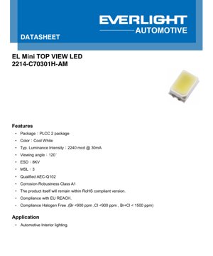
1. পণ্য সংক্ষিপ্ত বিবরণ
এই নথিটি PLCC-2 (প্লাস্টিক লিডড চিপ ক্যারিয়ার) প্যাকেজে নির্মিত, টপ-ভিউ ইমিশন ডিজাইনযুক্ত একটি উচ্চ-উজ্জ্বলতা পৃষ্ঠ-আবদ্ধ LED-এর বিবরণ বিস্তারিতভাবে বর্ণনা করে। এর প্রাথমিক প্রয়োগ ক্ষেত্র হল অটোমোটিভ অভ্যন্তরীণ আলোকসজ্জা, যেখানে নির্ভরযোগ্যতা, কর্মক্ষমতার সামঞ্জস্য এবং শিল্প মানদণ্ডের সাথে সঙ্গতির প্রয়োজনীয়তা অত্যন্ত কঠোর। ডিভাইসটি একটি কোল্ড হোয়াইট আলো নির্গত করে এবং কঠোর অটোমোটিভ-গ্রেড প্রয়োজনীয়তা পূরণের জন্য ডিজাইন করা হয়েছে, যার মধ্যে রয়েছে AEC-Q102 প্রত্যয়ন এবং নির্দিষ্ট জারা প্রতিরোধের মান।
1.1 মূল বৈশিষ্ট্য ও সুবিধা
এই LED কঠোর প্রয়োগের জন্য বেশ কয়েকটি মূল সুবিধা প্রদান করে। 30mA এর আদর্শ চালনা প্রবাহে, এর সাধারণ লুমিনাস ইনটেনসিটি হল 2240 মিলিক্যান্ডেলা (mcd), যা আলোকসজ্জার কাজের জন্য পর্যাপ্ত উজ্জ্বলতা সরবরাহ করে। 120 ডিগ্রির প্রশস্ত দর্শন কোণ সমান আলোর বণ্টন নিশ্চিত করে, যা পরিবেষ্টিত আলো এবং সূচক আলোকসজ্জার জন্য অত্যন্ত গুরুত্বপূর্ণ। AEC-Q102 (অটোমোটিভ অ্যাপ্লিকেশনের জন্য বিচ্ছিন্ন অপটোইলেকট্রনিক উপাদানের গ্লোবাল স্ট্রেস টেস্ট কোয়ালিফিকেশন) এর সাথে সঙ্গতি চরম পরিবেশগত অবস্থার অধীনে এর কর্মক্ষমতা নিশ্চিত করে। উপরন্তু, RoHS, REACH এবং হ্যালোজেন-মুক্ত মানের সাথে সঙ্গতি পরিবেশগত ও নিরাপত্তা নিয়ন্ত্রণীয় প্রয়োজনীয়তা পূরণ করে। ডিভাইসটিতে 8kV ESD (ইলেক্ট্রোস্ট্যাটিক ডিসচার্জ) সুরক্ষা রেটিং (হিউম্যান বডি মডেল) রয়েছে এবং এটিকে MSL 3 (ময়েশ্চার সেনসিটিভিটি লেভেল) হিসাবে রেট দেওয়া হয়েছে, যা সমাবেশ প্রক্রিয়ায় এর শক্তিশালী হ্যান্ডলিং বৈশিষ্ট্য নির্দেশ করে।
2. গভীর প্রযুক্তিগত প্যারামিটার বিশ্লেষণ
2.1 আলোকমিতি ও বৈদ্যুতিক বৈশিষ্ট্য
প্রধান অপারেটিং পয়েন্টটি ফরওয়ার্ড কারেন্ট (IF) 30mA হিসাবে সংজ্ঞায়িত করা হয়েছে। এই কারেন্টে, টাইপিকাল ফরওয়ার্ড ভোল্টেজ (VF) হল 3.1V, নির্দিষ্ট পরিসীমা 2.5V (ন্যূনতম) থেকে 3.75V (সর্বোচ্চ) পর্যন্ত। ফলে টাইপিকাল পাওয়ার খরচ প্রায় 93mW (3.1V * 0.03A)। মূল ফটোমেট্রিক আউটপুট হল লুমিনাস ইনটেনসিটি (IV) 2240 mcd, ন্যূনতম মান 1400 mcd, সর্বোচ্চ মান 4500 mcd পর্যন্ত হতে পারে, যা বিভিন্ন উৎপাদন বিনের মধ্যে পারফরম্যান্সের তারতম্য নির্দেশ করে। কুল হোয়াইট মডেলের জন্য, এর প্রভাবশালী ক্রোমাটিসিটি কোঅর্ডিনেট (CIE x, y) (0.3, 0.3) কেন্দ্রের চারপাশে বিতরণ করা হয়, সহনশীলতা হল ±0.005।
2.2 তাপীয় কর্মক্ষমতা ও পরম সর্বোচ্চ রেটিং
তাপ ব্যবস্থাপনা LED এর আয়ুস্কালের জন্য অত্যন্ত গুরুত্বপূর্ণ। জংশন থেকে সোল্ডার পয়েন্ট পর্যন্ত তাপীয় প্রতিরোধ দুটি মান নির্দিষ্ট করে: বৈদ্যুতিক পদ্ধতি (Rth JS el) সর্বোচ্চ 75 K/W, প্রকৃত পদ্ধতি (Rth JS real) সর্বোচ্চ 95 K/W। পরম সর্বোচ্চ রেটিং অপারেশনের সীমা নির্ধারণ করে: সর্বোচ্চ ক্রমাগত ফরোয়ার্ড কারেন্ট 60mA, সর্বোচ্চ পাওয়ার ডিসিপেশন 210mW, অপারেটিং জংশন তাপমাত্রা (TJ) সীমা 125°C। পরিবেশগত অপারেটিং তাপমাত্রার পরিসীমা -40°C থেকে +110°C। ≤10μs পালস অনুমোদিত হলে, সর্বোচ্চ সার্জ কারেন্ট (IFM) 250mA পর্যন্ত হতে পারে। এই ডিভাইসটি রিভার্স বায়াস অপারেশনের জন্য ডিজাইন করা হয়নি।
3. কর্মক্ষমতা বক্ররেখা বিশ্লেষণ
3.1 কারেন্ট-ভোল্টেজ এবং উজ্জ্বলতা সম্পর্ক
ফরওয়ার্ড কারেন্ট বনাম ফরওয়ার্ড ভোল্টেজ (I-V) কার্ভ প্রত্যাশিত সূচকীয় সম্পর্ক প্রদর্শন করে। আপেক্ষিক আলোকিত তীব্রতা বনাম ফরওয়ার্ড কারেন্টের গ্রাফ নির্দেশ করে যে, স্ট্যান্ডার্ড 30mA বিন্দু অতিক্রম করার পর, কারেন্ট বৃদ্ধির সাথে আলোর আউটপুট সাব-লিনিয়ারভাবে বৃদ্ধি পায়, যা সামঞ্জস্যপূর্ণ উজ্জ্বলতা বজায় রাখতে কারেন্ট নিয়ন্ত্রণের গুরুত্বকে জোর দেয়। ফরওয়ার্ড কারেন্ট ডিরেটিং কার্ভ ডিজাইনের জন্য অত্যন্ত গুরুত্বপূর্ণ: প্যাড তাপমাত্রা (TS) বৃদ্ধির সাথে, অনুমোদিত অবিচ্ছিন্ন ফরওয়ার্ড কারেন্ট অবশ্যই হ্রাস পেতে হবে। উদাহরণস্বরূপ, সর্বোচ্চ সুপারিশকৃত TS 110°C এ, সর্বোচ্চ অনুমোদিত IF হল 60mA।
3.2 তাপমাত্রা নির্ভরতা এবং বর্ণালী আউটপুট
আপেক্ষিক আলোকিত তীব্রতা বনাম জংশন তাপমাত্রার গ্রাফ একটি নেতিবাচক তাপমাত্রা সহগ প্রদর্শন করে; জংশন তাপমাত্রা বৃদ্ধির সাথে আলোর আউটপুট হ্রাস পায়। আপেক্ষিক ফরওয়ার্ড ভোল্টেজও তাপমাত্রা বৃদ্ধির সাথে হ্রাস পায়, যা পরোক্ষ তাপমাত্রা পর্যবেক্ষণের জন্য ব্যবহার করা যেতে পারে। ক্রোমাটিসিটি স্থানাঙ্কগুলি ফরওয়ার্ড কারেন্ট এবং জংশন তাপমাত্রার পরিবর্তনের সাথে সরে যায়, যা রঙ-সমালোচনামূলক অ্যাপ্লিকেশনের জন্য অত্যন্ত গুরুত্বপূর্ণ। তরঙ্গদৈর্ঘ্য বৈশিষ্ট্যগুলির গ্রাফ একটি কোল্ড হোয়াইট ফসফর-কনভার্টেড LED-এর আপেক্ষিক স্পেকট্রাল পাওয়ার ডিস্ট্রিবিউশন (SPD) প্রদর্শন করে, যা সাধারণত ব্লু পাম্প LED-এর একটি পিক এবং একটি বিস্তৃত ইয়েলো ফসফর নির্গমন ব্যান্ড দেখায়। বিকিরণ প্যাটার্ন ডায়াগ্রামটি একটি ল্যাম্বার্টিয়ান-সদৃশ বন্টনের 120° ভিউিং অ্যাঙ্গেলকে চাক্ষুষভাবে নিশ্চিত করে।
4. বিনিং সিস্টেমের বিবরণ
এই LED একই উৎপাদন ব্যাচের মধ্যে সামঞ্জস্য নিশ্চিত করার জন্য পারফরম্যান্স অনুযায়ী গ্রুপিংয়ের বিকল্প প্রদান করে, যাকে বিনিং বলা হয়।
4.1 লুমিনাস ইনটেনসিটি গ্রেডিং
ডেটাশীটে L1 থেকে GA কোড পর্যন্ত বিস্তৃত লুমিনাস ইনটেনসিটি বিনিং টেবিল প্রদান করা হয়েছে। প্রতিটি বিন মিলিক্যান্ডেলায় (mcd) সংজ্ঞায়িত সর্বনিম্ন এবং সর্বোচ্চ লুমিনাস ইনটেনসিটির মান নির্ধারণ করে। এই নির্দিষ্ট মডেলের জন্য (2214-C70301H-AM), সম্ভাব্য আলোক আউটপুট বিন হাইলাইট করা হয়েছে, যেখানে 2240 mcd-এর টাইপিক্যাল মান "BA" বিন (1800-2240 mcd) বা "BB" বিন (2240-2800 mcd) এর মধ্যে পড়ে। ডিজাইনারদের অবশ্যই সর্বনিম্ন প্রয়োজনীয় উজ্জ্বলতা নির্দিষ্ট করার সময় এই পরিসরটি বিবেচনা করতে হবে।
4.2 ক্রোমাটিসিটি কোঅর্ডিনেট গ্রেডিং (কোল্ড হোয়াইট)
CIE 1931 (x, y) ক্রোমাটিসিটি কোঅর্ডিনেট ব্যবহার করে একটি স্ট্যান্ডার্ড কুল হোয়াইট কালার বিনিং স্ট্রাকচার সংজ্ঞায়িত করা হয়েছে। এই কাঠামোটি একটি আয়তক্ষেত্রাকার বিন গ্রিড (যেমন L10, L20, K10 ইত্যাদি) হিসাবে উপস্থাপিত হয়, যেখানে প্রতিটি বিন তিনটি কোঅর্ডিনেট জোড়া দ্বারা সংজ্ঞায়িত হয় যা ক্রোমাটিসিটি ডায়াগ্রামে একটি ত্রিভুজ গঠন করে। এটি এমন LED নির্বাচন করা সম্ভব করে যা রঙের চেহারায় অত্যন্ত সদৃশ, যা একাধিক LED অ্যারে-তে দৃশ্যমান রঙের পার্থক্য এড়ানোর জন্য অত্যন্ত গুরুত্বপূর্ণ।
5. যান্ত্রিক গঠন, সংযোজন ও প্যাকেজিং
5.1 শারীরিক মাত্রা ও পোলারিটি
মেকানিক্যাল ড্রয়িং (PDF ফাইল দেখুন) PLCC-2 প্যাকেজের সঠিক মাত্রা সংজ্ঞায়িত করে। প্রধান মাত্রার মধ্যে রয়েছে মোট দৈর্ঘ্য, প্রস্থ, উচ্চতা, পাশাপাশি পিন পিচ এবং মাত্রা। টপ-ভিউ ডিজাইনের অর্থ হল আলো ইনস্টলেশন সমতলের সাথে লম্বভাবে নির্গত হয়। প্যাকেজে পোলারিটি নির্দেশক থাকে, যা সাধারণত একটি খাঁজ বা চিহ্নিত ক্যাথোড, PCB অ্যাসেম্বলি প্রক্রিয়ায় সঠিক অভিযোজন নিশ্চিত করার জন্য।
5.2 সোল্ডারিং ও রিফ্লো সোল্ডারিং নির্দেশিকা
নির্ভরযোগ্য সোল্ডার জয়েন্ট এবং LED থার্মাল প্যাড থেকে PCB-তে সর্বোত্তম তাপ স্থানান্তর নিশ্চিত করতে প্রস্তাবিত প্যাড প্যাটার্ন প্রদান করা হয়েছে। রিফ্লো প্রোফাইল ক্ষতি রোধ করতে সর্বোচ্চ তাপমাত্রা এবং সময় সীমা নির্ধারণ করে। এই প্রোফাইল সাধারণত IPC/JEDEC স্ট্যান্ডার্ড অনুসরণ করে, যার সর্বোচ্চ তাপমাত্রা 260°C এবং সর্বোচ্চ 30 সেকেন্ড স্থায়িত্ব। MSL 3 রেটিং প্রয়োজন যে, যদি ডিভাইসটি রিফ্লোর আগে 168 ঘন্টার বেশি পরিবেশগত বাতাসে উন্মুক্ত থাকে, তবে আর্দ্রতা বাষ্পীভবনের কারণে "পপকর্ন" ক্ষতি রোধ করতে অবশ্যই বেকিং করতে হবে।
5.3 প্যাকেজিং তথ্য
LED গুলি অটোমেটেড পিক-অ্যান্ড-প্লেস অ্যাসেম্বলির জন্য রিল টেপে সরবরাহ করা হয়। প্যাকেজিং তথ্যে রিলের মাত্রা, ক্যারিয়ার টেপের প্রস্থ, পকেট পিচ এবং ক্যারিয়ার টেপে ডিভাইসের অভিযোজন বিস্তারিত বর্ণনা করা হয়েছে। এই ডেটা অ্যাসেম্বলি সরঞ্জাম প্রোগ্রাম করার জন্য অত্যন্ত গুরুত্বপূর্ণ।
6. অ্যাপ্লিকেশন নির্দেশিকা ও ডিজাইন বিবেচনা
6.1 প্রধান অ্যাপ্লিকেশন: গাড়ির অভ্যন্তরীণ আলোকসজ্জা
এই LED টি গাড়ির অভ্যন্তরীণ আলোকসজ্জা অ্যাপ্লিকেশনের জন্য বিশেষভাবে ডিজাইন করা হয়েছে। এর মধ্যে রয়েছে ড্যাশবোর্ড ব্যাকলাইট, সুইচ আলো, ফুটওয়েল আলো, ডোর প্যানেল লাইট এবং পরিবেষ্টিত পরিবেশ আলো। AEC-Q102 সার্টিফিকেশন নিশ্চিত করে যে এটি গাড়ির পরিবেশে চরম তাপমাত্রা, আর্দ্রতা, কম্পন এবং দীর্ঘমেয়াদী নির্ভরযোগ্যতার প্রয়োজনীয়তা সহ্য করতে সক্ষম।
6.2 সার্কিট ডিজাইন এবং তাপ ব্যবস্থাপনা
স্থিতিশীল এবং দীর্ঘস্থায়ী কর্মক্ষমতা নিশ্চিত করতে, বিশেষ করে ওঠানামা করতে পারে এমন গাড়ির ভোল্টেজ বাসের জন্য, একটি সিরিজ রেজিস্টর সহ ধ্রুব ভোল্টেজ উৎসের পরিবর্তে একটি ধ্রুব কারেন্ট ড্রাইভার ব্যবহার করার জন্য জোরালোভাবে সুপারিশ করা হয়। ড্রাইভারটি এমনভাবে ডিজাইন করা উচিত যাতে সাধারণ ব্যবহারে I কে 30mA-এ সীমাবদ্ধ রাখা হয়, অথবা যদি উচ্চ পরিবেষ্টিত তাপমাত্রা প্রত্যাশিত হয় তবে ডিরেটিং কার্ভ অনুযায়ী ডিজাইন করা হয়।F কার্যকর তাপ ব্যবস্থাপনা অপরিহার্য। PCB-তে LED-এর তাপীয় প্যাডের সাথে সংযুক্ত পর্যাপ্ত বড় তামার এলাকা থাকা উচিত যা হিট সিঙ্ক হিসাবে কাজ করবে, যাতে সোল্ডার জয়েন্টের তাপমাত্রা (T) যতটা সম্ভব কম রাখা যায়, আলোর আউটপুট এবং আয়ু বজায় রাখার জন্য।S) যতটা সম্ভব কম রাখা যায়, আলোর আউটপুট এবং আয়ু বজায় রাখার জন্য।
6.3 ব্যবহারের সময় সতর্কতা
সাধারণ সতর্কতার মধ্যে রয়েছে LED লেন্সে যান্ত্রিক চাপ প্রয়োগ এড়ানো, সালফারযুক্ত পরিবেশে প্রকাশ রোধ করা (যা রূপালী প্রলেপযুক্ত অংশগুলিকে ক্ষয় করতে পারে), এবং 8kV প্রতিরক্ষামূলক স্তর থাকা সত্ত্বেও সমাবেশ প্রক্রিয়ায় উপযুক্ত ESD হ্যান্ডলিং পদ্ধতি ব্যবহার করা। ডিভাইসটি বিপরীত পক্ষপাত ভোল্টেজে কাজ করা উচিত নয়। অপটিক্যাল ডিজাইনে প্রত্যাশিত আলোর প্যাটার্ন অর্জনের জন্য 120° দর্শন কোণ বিবেচনা করা উচিত।
7. অর্ডার এবং মডেল তথ্য
মডেল 2214-C70301H-AM একটি নির্দিষ্ট কোডিং সিস্টেম অনুসরণ করে। যদিও সম্পূর্ণ বিশ্লেষণ মালিকানাধীন হতে পারে, এটি সাধারণত প্যাকেজ টাইপ (2214 সম্ভবত PLCC-2 এর 2.2mm x 1.4mm প্যাড আকার নির্দেশ করে), রঙ (C শীতল সাদা আলোর জন্য দাঁড়ায়), আলোকিত তীব্রতা গ্রেডিং এবং সম্ভাব্য বিশেষ বৈশিষ্ট্য বা সংশোধন (AM) এর মতো তথ্য এনকোড করে। অর্ডারিং তথ্য প্রতি রিলে পরিমাণ এবং রঙ বা তীব্রতার জন্য ঐচ্ছিক গ্রেডিং বিকল্প নির্দিষ্ট করবে।
8. প্রযুক্তিগত তুলনা এবং সাধারণ প্রশ্ন
8.1 স্ট্যান্ডার্ড LED এর সাথে পার্থক্য
এই LED-এর মূল পার্থক্য হল এর অটোমোটিভ-গ্রেড সার্টিফিকেশন (AEC-Q102) এবং সম্পর্কিত নির্ভরযোগ্যতা পরীক্ষা, এর নির্দিষ্ট ক্ষয় প্রতিরোধের রেটিং (গ্রেড A1), এবং এর অটোমোটিভ-সম্পর্কিত পরিবেশগত প্রবিধান (REACH, হ্যালোজেন-মুক্ত) মেনে চলা। স্ট্যান্ডার্ড কমার্শিয়াল-গ্রেড PLCC-2 LED একই কঠোর পরীক্ষার মধ্য দিয়ে যায় না এবং -40°C থেকে +110°C তাপমাত্রার পরিসরে নির্ভরযোগ্যভাবে কাজ করতে সক্ষম নাও হতে পারে।
8.2 সাধারণ প্রশ্নাবলী
প্রশ্ন: এই LED-এর সাধারণ আলোক দক্ষতা (লুমেন প্রতি ওয়াট) কত?
উত্তর: ডেটাশীট লুমেন নয়, মিলিক্যান্ডেলায় আলোক তীব্রতা নির্দিষ্ট করে। আনুমানিক লুমেন মান গণনা করতে, দৃশ্য কোণ বিবেচনা করতে হবে। 120° দৃশ্য কোণ এবং 2240 mcd-এর জন্য, সাধারণ আলোক প্রবাহ প্রায় 6-8 লুমেন। 93mW শক্তি খরচে, এটি প্রায় 65-85 lm/W আলোক দক্ষতা তৈরি করে।
প্রশ্ন: আমি কি 12V গাড়ির ব্যাটারি দিয়ে সরাসরি এই LED চালাতে পারি?
উত্তর: না। এর ফরওয়ার্ড ভোল্টেজ মাত্র ~3.1V। 12V-এর সাথে সরাসরি সংযোগ করলে তা তাৎক্ষণিকভাবে ক্ষতিগ্রস্ত হবে। একটি কারেন্ট-লিমিটিং সার্কিট ব্যবহার করতে হবে, যেমন একটি লিনিয়ার কনস্ট্যান্ট কারেন্ট ড্রাইভার বা একটি সুইচিং বাক কনভার্টার।
প্রশ্ন: আমার অ্যাপ্লিকেশনের জন্য সঠিক ইনটেনসিটি বিন কীভাবে বেছে নেব?
উত্তর: বিনের সর্বনিম্ন আলোক তীব্রতা মান ব্যবহার করুন, সাধারণ বা সর্বোচ্চ মান নয়। এমনভাবে আপনার অপটিক্যাল সিস্টেম ডিজাইন করুন যাতে ক্রয় আদেশে অনুমোদিত সর্বনিম্ন কর্মক্ষমতা বিনের LED ব্যবহার করেও উজ্জ্বলতা প্রয়োজনীয়তা পূরণ হয়। এটি ফলন এবং সামঞ্জস্য নিশ্চিত করে।
প্রশ্ন: "ক্ষয় প্রতিরোধের গ্রেড A1" এর অর্থ কী?
উত্তর: এই গ্রেডটি সাধারণত প্রস্তুতকারক বা গ্রাহক স্পেসিফিকেশন দ্বারা সংজ্ঞায়িত করা হয়, যা নির্দেশ করে যে LED টি নির্দিষ্ট ত্বরিত ক্ষয় পরীক্ষা (যেমন মিশ্র প্রবাহ গ্যাস পরীক্ষা) পাস করেছে। এই পরীক্ষাগুলি প্রতিকূল পরিবেশগত অবস্থার অনুকরণ করে, যা নিশ্চিত করে যে প্যাকেজিং এবং পিনগুলি পণ্যের জীবনচক্রে ক্ষয় প্রতিরোধ করতে সক্ষম।
LED স্পেসিফিকেশন পরিভাষার বিস্তারিত ব্যাখ্যা
LED প্রযুক্তিগত পরিভাষার সম্পূর্ণ ব্যাখ্যা
১. আলোক-বৈদ্যুতিক কর্মক্ষমতার মূল সূচক
| পরিভাষা | একক/প্রতীক | সাধারণ ব্যাখ্যা | কেন গুরুত্বপূর্ণ |
|---|---|---|---|
| আলোক দক্ষতা (Luminous Efficacy) | lm/W (লুমেন/ওয়াট) | প্রতি ওয়াট বিদ্যুৎ শক্তি থেকে নির্গত আলোক প্রবাহ, যত বেশি হবে তত বেশি শক্তি সাশ্রয়ী। | সরাসরি আলোর যন্ত্রের শক্তি দক্ষতার স্তর এবং বিদ্যুৎ বিলের খরচ নির্ধারণ করে। |
| আলোক প্রবাহ (Luminous Flux) | lm (লুমেন) | আলোর উৎস থেকে নির্গত মোট আলোর পরিমাণ, সাধারণভাবে "উজ্জ্বলতা" নামে পরিচিত। | ল্যাম্পটি যথেষ্ট উজ্জ্বল কিনা তা নির্ধারণ করে। |
| আলোক নির্গমন কোণ (Viewing Angle) | ° (ডিগ্রী), যেমন 120° | আলোর তীব্রতা অর্ধেক কমে যাওয়ার কোণ, যা আলোর রশ্মির প্রস্থ নির্ধারণ করে। | আলোকিত এলাকার পরিসর এবং সমতা প্রভাবিত করে। |
| বর্ণ তাপমাত্রা (CCT) | K (কেলভিন), যেমন 2700K/6500K | আলোর রঙের উষ্ণতা বা শীতলতা, কম মান হলুদ/উষ্ণ, বেশি মান সাদা/শীতল নির্দেশ করে। | আলোর পরিবেশ এবং প্রযোজ্য পরিস্থিতি নির্ধারণ করে। |
| রঙ রেন্ডারিং সূচক (CRI / Ra) | এককহীন, ০–১০০ | আলোর উৎস দ্বারা বস্তুর প্রকৃত রঙ পুনরুৎপাদনের ক্ষমতা, Ra≥৮০ উত্তম। | রঙের বাস্তবতাকে প্রভাবিত করে, শপিং মল, আর্ট গ্যালারির মতো উচ্চ চাহিদাসম্পন্ন স্থানে ব্যবহৃত হয়। |
| রঙ সহনশীলতা (SDCM) | ম্যাকঅ্যাডাম উপবৃত্ত ধাপ সংখ্যা, যেমন "5-step" | রঙের সামঞ্জস্যের পরিমাণগত সূচক, পদক্ষেপ যত কম, রঙ তত বেশি সামঞ্জস্যপূর্ণ। | একই ব্যাচের আলোর যন্ত্রগুলির রঙে কোন পার্থক্য নেই তা নিশ্চিত করা। |
| Dominant Wavelength | nm (ন্যানোমিটার), যেমন 620nm (লাল) | রঙিন LED রঙের সাথে সম্পর্কিত তরঙ্গদৈর্ঘ্যের মান। | লাল, হলুদ, সবুজ ইত্যাদি একরঙা LED-এর রঙের আভা নির্ধারণ করে। |
| বর্ণালী বণ্টন (Spectral Distribution) | তরঙ্গদৈর্ঘ্য বনাম তীব্রতা বক্ররেখা | LED থেকে নির্গত আলোর বিভিন্ন তরঙ্গদৈর্ঘ্যে তীব্রতা বণ্টন প্রদর্শন করে। | বর্ণ প্রতিপাদন ও রঙের গুণমানকে প্রভাবিত করে। |
দুই. বৈদ্যুতিক প্যারামিটার
| পরিভাষা | প্রতীক | সাধারণ ব্যাখ্যা | নকশা বিবেচ্য বিষয় |
|---|---|---|---|
| ফরওয়ার্ড ভোল্টেজ (Forward Voltage) | Vf | LED জ্বালানোর জন্য প্রয়োজনীয় সর্বনিম্ন ভোল্টেজ, একপ্রকার "চালু হওয়ার প্রান্তিক মান"। | ড্রাইভার পাওয়ার সাপ্লাই ভোল্টেজ ≥ Vf হতে হবে, একাধিক LED সিরিজে সংযুক্ত হলে ভোল্টেজ যোগ হয়। |
| ফরওয়ার্ড কারেন্ট (Forward Current) | If | LED কে স্বাভাবিকভাবে আলোকিত করার জন্য প্রয়োজনীয় কারেন্টের মান। | সাধারণত ধ্রুব কারেন্ট ড্রাইভ ব্যবহার করা হয়, কারেন্ট উজ্জ্বলতা ও আয়ু নির্ধারণ করে। |
| সর্বোচ্চ পালস কারেন্ট (Pulse Current) | Ifp | স্বল্প সময়ের জন্য সহনীয় শিখর কারেন্ট, ডিমিং বা ফ্ল্যাশের জন্য ব্যবহৃত। | পালস প্রস্থ এবং ডিউটি সাইকেল কঠোরভাবে নিয়ন্ত্রণ করতে হবে, অন্যথায় অতিরিক্ত গরম হয়ে ক্ষতি হতে পারে। |
| Reverse Voltage | Vr | LED দ্বারা সহনীয় সর্বোচ্চ বিপরীত ভোল্টেজ, অতিক্রম করলে ব্রেকডাউন হতে পারে। | সার্কিটে বিপরীত সংযোগ বা ভোল্টেজ স্পাইক প্রতিরোধ করতে হবে। |
| Thermal Resistance | Rth (°C/W) | চিপ থেকে সোল্ডার পয়েন্টে তাপ প্রবাহের প্রতিরোধ, মান যত কম হবে তাপ অপসারণ তত ভালো। | উচ্চ তাপীয় রোধের জন্য শক্তিশালী তাপ অপসারণ নকশা প্রয়োজন, অন্যথায় জংশন তাপমাত্রা বৃদ্ধি পায়। |
| ইলেক্ট্রোস্ট্যাটিক ডিসচার্জ ইমিউনিটি (ESD Immunity) | V (HBM), যেমন 1000V | ইলেক্ট্রোস্ট্যাটিক শক প্রতিরোধের ক্ষমতা, মান যত বেশি হবে স্ট্যাটিক বিদ্যুৎ দ্বারা ক্ষতিগ্রস্ত হওয়ার সম্ভাবনা তত কম। | উৎপাদন প্রক্রিয়ায় স্থির বিদ্যুৎ প্রতিরোধী ব্যবস্থা গ্রহণ করতে হবে, বিশেষ করে উচ্চ সংবেদনশীল LED-এর ক্ষেত্রে। |
তিন. তাপ ব্যবস্থাপনা ও নির্ভরযোগ্যতা
| পরিভাষা | মূল সূচক | সাধারণ ব্যাখ্যা | প্রভাব |
|---|---|---|---|
| জাংশন তাপমাত্রা (Junction Temperature) | Tj (°C) | LED চিপের অভ্যন্তরীণ প্রকৃত অপারেটিং তাপমাত্রা। | প্রতি 10°C হ্রাসে, আয়ু দ্বিগুণ হতে পারে; অত্যধিক তাপমাত্রা আলোক ক্ষয় এবং বর্ণ পরিবর্তনের কারণ হয়। |
| Lumen Depreciation | L70 / L80 (ঘন্টা) | উজ্জ্বলতা প্রাথমিক মানের 70% বা 80% এ পৌঁছাতে প্রয়োজনীয় সময়। | LED-এর "সেবা জীবন" সরাসরি সংজ্ঞায়িত করে। |
| লুমেন রক্ষণাবেক্ষণ হার (Lumen Maintenance) | % (যেমন 70%) | কিছু সময় ব্যবহারের পর অবশিষ্ট উজ্জ্বলতার শতাংশ। | দীর্ঘমেয়াদী ব্যবহারের পর উজ্জ্বলতা ধরে রাখার ক্ষমতা বর্ণনা করে। |
| রঙের সরণ (Color Shift) | Δu′v′ অথবা MacAdam Ellipse | ব্যবহারের সময় রঙের পরিবর্তনের মাত্রা। | আলোক দৃশ্যের রঙের সামঞ্জস্যকে প্রভাবিত করে। |
| তাপীয় বার্ধক্য (Thermal Aging) | উপাদানের কার্যকারিতা হ্রাস | দীর্ঘমেয়াদী উচ্চ তাপমাত্রার কারণে এনক্যাপসুলেশন উপাদানের অবনতি। | উজ্জ্বলতা হ্রাস, রঙের পরিবর্তন বা ওপেন সার্কিট ব্যর্থতার কারণ হতে পারে। |
চার. প্যাকেজিং ও উপকরণ
| পরিভাষা | সাধারণ প্রকার | সাধারণ ব্যাখ্যা | বৈশিষ্ট্য এবং প্রয়োগ |
|---|---|---|---|
| এনক্যাপসুলেশন প্রকার | EMC, PPA, সিরামিক | চিপ সুরক্ষা এবং অপটিক্যাল, থার্মাল ইন্টারফেস প্রদানকারী আবরণ উপকরণ। | EMC তাপ প্রতিরোধী ভাল, খরচ কম; সিরামিক তাপ অপসারণে উৎকৃষ্ট, দীর্ঘ আয়ু। |
| চিপ কাঠামো | ফরওয়ার্ড-মাউন্ট, ফ্লিপ চিপ (Flip Chip) | চিপ ইলেক্ট্রোড বিন্যাস পদ্ধতি। | ফ্লিপ চিপ তাপ অপসারণ ভাল, আলোক দক্ষতা বেশি, উচ্চ শক্তির জন্য উপযুক্ত। |
| ফসফর আবরণ | YAG, সিলিকেট, নাইট্রাইড | নীল আলোর চিপের উপর প্রলেপ দেওয়া হয়, যা আংশিকভাবে হলুদ/লাল আলোতে রূপান্তরিত হয় এবং সাদা আলোতে মিশ্রিত হয়। | বিভিন্ন ফসফর আলোর কার্যকারিতা, রঙের তাপমাত্রা এবং রঙ রেন্ডারিংকে প্রভাবিত করে। |
| লেন্স/অপটিক্যাল ডিজাইন | সমতল, মাইক্রোলেন্স, টোটাল ইন্টার্নাল রিফ্লেকশন | প্যাকেজিং পৃষ্ঠের অপটিক্যাল কাঠামো, যা আলোর বন্টন নিয়ন্ত্রণ করে। | আলোক নির্গমন কোণ এবং আলোক বণ্টন বক্ররেখা নির্ধারণ করে। |
পাঁচ. গুণমান নিয়ন্ত্রণ ও গ্রেডিং
| পরিভাষা | গ্রেডিং বিষয়বস্তু | সাধারণ ব্যাখ্যা | উদ্দেশ্য |
|---|---|---|---|
| লুমিনাস ফ্লাক্স গ্রেডিং | কোড যেমন 2G, 2H | উজ্জ্বলতার উচ্চ-নিম্ন অনুযায়ী গ্রুপিং, প্রতিটি গ্রুপের সর্বনিম্ন/সর্বোচ্চ লুমেন মান রয়েছে। | একই ব্যাচের পণ্যের উজ্জ্বলতা সামঞ্জস্যপূর্ণ তা নিশ্চিত করুন। |
| ভোল্টেজ গ্রেডিং | কোড যেমন 6W, 6X | ফরওয়ার্ড ভোল্টেজ রেঞ্জ অনুযায়ী গ্রুপিং। | ড্রাইভার পাওয়ার সাপ্লাই ম্যাচিং সুবিধার্থে, সিস্টেম দক্ষতা উন্নত করতে। |
| রঙের পার্থক্য গ্রেডিং | 5-step MacAdam ellipse | রঙের স্থানাঙ্ক অনুযায়ী গ্রুপিং, নিশ্চিত করুন যে রঙ অত্যন্ত সংকীর্ণ সীমার মধ্যে পড়ে। | রঙের সামঞ্জস্য নিশ্চিত করুন, একই ল্যাম্পের ভিতরে রঙের অসামঞ্জস্যতা এড়িয়ে চলুন। |
| কোর রঙের তাপমাত্রা গ্রেডিং | 2700K, 3000K ইত্যাদি | রঙের তাপমাত্রা অনুযায়ী গ্রুপ করা হয়েছে, প্রতিটি গ্রুপের জন্য সংশ্লিষ্ট স্থানাঙ্ক পরিসীমা রয়েছে। | বিভিন্ন দৃশ্যের রঙের তাপমাত্রার চাহিদা পূরণ করে। |
ছয়. পরীক্ষণ ও প্রত্যয়ন
| পরিভাষা | মান/পরীক্ষা | সাধারণ ব্যাখ্যা | তাৎপর্য |
|---|---|---|---|
| LM-80 | লুমেন রক্ষণাবেক্ষণ পরীক্ষা | ধ্রুব তাপমাত্রার শর্তে দীর্ঘমেয়াদী আলোকসজ্জার মাধ্যমে উজ্জ্বলতা হ্রাসের তথ্য রেকর্ড করা হয়। | LED-এর আয়ু অনুমান করতে ব্যবহৃত হয় (TM-21-এর সাথে সমন্বয় করে)। |
| TM-21 | আয়ু অনুমান প্রমিতকরণ | LM-80 তথ্যের ভিত্তিতে বাস্তব ব্যবহারের শর্তে আয়ু অনুমান করা। | বৈজ্ঞানিক আয়ু পূর্বাভাস প্রদান করা। |
| IESNA স্ট্যান্ডার্ড | ইলুমিনেটিং ইঞ্জিনিয়ারিং সোসাইটি স্ট্যান্ডার্ড | অপটিক্যাল, বৈদ্যুতিক, তাপীয় পরীক্ষা পদ্ধতি অন্তর্ভুক্ত করে। | শিল্প-স্বীকৃত পরীক্ষার ভিত্তি। |
| RoHS / REACH | পরিবেশগত প্রত্যয়ন | পণ্যটি ক্ষতিকারক পদার্থ (যেমন সীসা, পারদ) মুক্ত তা নিশ্চিত করা। | আন্তর্জাতিক বাজারে প্রবেশের শর্তাবলী। |
| ENERGY STAR / DLC | শক্তি দক্ষতা প্রত্যয়ন | আলোকসজ্জা পণ্যের জন্য শক্তি দক্ষতা ও কার্যকারিতা প্রত্যয়ন। | সরকারী ক্রয়, ভর্তুকি প্রকল্পে সাধারণত ব্যবহৃত, বাজার প্রতিযোগিতা বৃদ্ধি করে। |