কন্টেন্ট
- 1. পণ্য সংক্ষিপ্ত বিবরণ
- 2. গভীর প্রযুক্তিগত প্যারামিটার বিশ্লেষণ
- 2.1 পরম সর্বোচ্চ রেটিং
- 2.2 অপটোইলেকট্রিক বৈশিষ্ট্য
- 3. গ্রেডিং সিস্টেমের বিবরণ
- 3.1 লুমিনাস ইনটেনসিটি গ্রেডিং
- 3.2 ফরওয়ার্ড ভোল্টেজ গ্রেডিং
- 3.3 কালার গ্রেডিং (ক্রোমাটিসিটি)
- 4. পারফরম্যান্স কার্ভ বিশ্লেষণ
- 4.1 আপেক্ষিক তীব্রতা বনাম তরঙ্গদৈর্ঘ্য
- 4.2 নির্দেশক চিত্র
- 4.3 ফরোয়ার্ড কারেন্ট বনাম ফরোয়ার্ড ভোল্টেজ (I-V কার্ভ)
- 4.4 আপেক্ষিক তীব্রতা বনাম ফরোয়ার্ড কারেন্ট
- 4.5 ক্রোমাটিসিটি স্থানাঙ্ক বনাম ফরোয়ার্ড কারেন্ট
- 4.6 ফরোয়ার্ড কারেন্ট বনাম পরিবেষ্টন তাপমাত্রা
- 5. যান্ত্রিক ও প্যাকেজিং তথ্য
- 5.1 প্যাকেজ মাত্রা
- 6. সোল্ডারিং ও অ্যাসেম্বলি নির্দেশিকা
- 6.1 পিন গঠন
- 6.2 সংরক্ষণ শর্ত
- 6.3 সোল্ডারিং প্রক্রিয়া
- ৭. প্যাকেজিং ও অর্ডার তথ্য
- ৭.১ প্যাকেজিং স্পেসিফিকেশন
- ৭.২ লেবেল নির্দেশনা
- ৭.৩ মডেল নামকরণ নিয়ম
- এর নির্দিষ্ট কোড। এটি ব্যবহারকারীদের তাদের প্রয়োগের জন্য প্রয়োজনীয় সঠিক কর্মক্ষমতা বৈশিষ্ট্য নির্দিষ্ট করতে সক্ষম করে।
- 8. প্রয়োগের সুপারিশ ও ডিজাইন বিবেচনা
- আলোকসজ্জা বা সংকেত নির্দেশনা প্রদান করে।
- রঙের চেহারা সমান রাখার প্রয়োজন এমন প্রয়োগের জন্য, কঠোর রঙের গ্রেড (HUE) নির্দিষ্ট করা উচিত এবং অ্যারেতে থাকা সমস্ত LED যেন একই বা সংলগ্ন গ্রেড থেকে আসে তা নিশ্চিত করতে হবে।
- এই LED-এর প্রধান পার্থক্য হল এটি ক্লাসিক এবং ব্যাপকভাবে গৃহীত T-1 3/4 প্যাকেজকে উষ্ণ সাদা আলো নির্গমনের জন্য উচ্চ আলোকিত তীব্রতার সাথে একত্রিত করে। ছোট SMD LED-এর তুলনায়, থ্রু-হোল ডিজাইন প্রোটোটাইপিং, ম্যানুয়াল অ্যাসেম্বলি বা উচ্চতর একক-বিন্দু উজ্জ্বলতা প্রয়োজন এমন অ্যাপ্লিকেশনগুলিতে সুবিধা প্রদান করতে পারে। বিপরীত ভোল্টেজ সুরক্ষার জন্য জেনার ডায়োড ইন্টিগ্রেশন একটি উল্লেখযোগ্য বৈশিষ্ট্য, যা বিপরীত ভোল্টেজ স্পাইক ঘটতে পারে এমন সার্কিট ডিজাইনে দৃঢ়তা বৃদ্ধি করে। বিস্তারিত মাল্টি-প্যারামিটার বিনিং সিস্টেম (তীব্রতা, ভোল্টেজ, রঙ) ডিজাইনারদের চূড়ান্ত পণ্যের কর্মক্ষমতা এবং সামঞ্জস্যের উপর উচ্চ মাত্রার নিয়ন্ত্রণ প্রদান করে, যা বাল্ক উৎপাদনের জন্য অত্যন্ত গুরুত্বপূর্ণ।
- 10. প্রায়শই জিজ্ঞাসিত প্রশ্ন (প্রযুক্তিগত স্পেসিফিকেশনের উপর ভিত্তি করে)
- (উদাহরণস্বরূপ, বিন 3 হল 3.6V) যাতে সবচেয়ে খারাপ অবস্থায় কারেন্ট 20mA-এর বেশি না হয়। সর্বোত্তম স্থিতিশীলতা এবং দক্ষতার জন্য, বিশেষ করে অ্যারেতে বা উচ্চতর কারেন্ট ব্যবহার করার সময়, একটি কনস্ট্যান্ট কারেন্ট ড্রাইভার ব্যবহারের সুপারিশ করা হয়।
- পরিবেষ্টিত তাপমাত্রা বৃদ্ধির সাথে, LED-এর ফরওয়ার্ড ভোল্টেজ সামান্য হ্রাস পায়, কিন্তু এর অভ্যন্তরীণ দক্ষতা কমে যেতে পারে, যার ফলে একই কারেন্টে আলোর আউটপুট হ্রাস পায়। আরও গুরুত্বপূর্ণভাবে, অত্যধিক উচ্চ তাপমাত্রা LED-এর অপারেশনাল জীবনকাল হ্রাস করে। ফরওয়ার্ড কারেন্ট বনাম পরিবেষ্টিত তাপমাত্রা ডিরেটিং কার্ভ অবশ্যই উল্লেখ করা উচিত এবং উপযুক্ত তাপীয় নকশার মাধ্যমে জংশন তাপমাত্রা নিরাপদ সীমার মধ্যে রাখা নিশ্চিত করা উচিত।
- এটি একটি ফসফর-রূপান্তরিত উষ্ণ সাদা LED, একরঙা LED নয়। এটি RGB মিশ্রণের জন্য ডিজাইন করা হয়নি। মিশ্রণের জন্য নির্দিষ্ট লাল, সবুজ, নীল (RGB) LED ব্যবহার করা উচিত।
- ) 100 mA রেটিংটি এই সুরক্ষামূলক ভূমিকায় এর কারেন্ট পরিচালনার ক্ষমতা নির্দেশ করে।
- 20mA, তারা সিরিজ রেজিস্টর গণনা করে: R = (12V - 3.6V) / 0.02A = 420Ω। একটি স্ট্যান্ডার্ড 430Ω, 1/4W রেজিস্টর নির্বাচন করা হয়। তারা অ্যাসেম্বলি নির্দেশিকা অনুসরণ করে, ঢোকানোর আগে লিডগুলিকে বডি থেকে 4mm দূরে বাঁকায়। চূড়ান্ত ইন্ডিকেটরটি পরিবেষ্টিত আলোতেও উৎকৃষ্ট দৃশ্যমানতা প্রদান করে এবং সামঞ্জস্যপূর্ণ বিনিং উৎপাদন লাইনে সমস্ত ইউনিটের অভিন্ন চেহারা নিশ্চিত করে।
- এই LED-টি সেমিকন্ডাক্টর ইলেক্ট্রোলুমিনেসেন্স নীতির উপর কাজ করে। এর মূল হল একটি InGaN চিপ। যখন ফরওয়ার্ড ভোল্টেজ প্রয়োগ করা হয়, তখন ইলেকট্রন এবং হোলগুলি চিপের সক্রিয় অঞ্চলে পুনর্মিলিত হয় এবং ফোটন আকারে শক্তি মুক্ত করে। InGaN খাদের নির্দিষ্ট উপাদান এই নির্গত আলোকে নীল তরঙ্গদৈর্ঘ্য পরিসরে স্থাপন করে। সাদা আলো তৈরি করতে, নীল আলোকে রিফ্লেক্টর কাপের ভিতরের ফসফর আবরণের দিকে পরিচালিত করা হয়। ফসফর কিছু নীল ফোটন শোষণ করে এবং দীর্ঘতর হলুদ ও লাল তরঙ্গদৈর্ঘ্যে পুনরায় আলো নির্গত করে। অবশিষ্ট নীল আলো ফসফর-রূপান্তরিত হলুদ/লাল আলোর সাথে মিশে যায়, যা মানব চোখ দ্বারা উষ্ণ সাদা আলো হিসাবে অনুভূত হয়। সঠিক বর্ণ (সম্পর্কিত রঙের তাপমাত্রা) ফসফরের উপাদান এবং ঘনত্ব দ্বারা নির্ধারিত হয়।
- LED স্পেসিফিকেশন পরিভাষার বিস্তারিত ব্যাখ্যা
- এক. আলোক-বৈদ্যুতিক কর্মক্ষমতার মূল সূচক
- দুই. বৈদ্যুতিক প্যারামিটার
- তিন. তাপ ব্যবস্থাপনা ও নির্ভরযোগ্যতা
- চার, প্যাকেজিং ও উপকরণ
- পাঁচ, গুণমান নিয়ন্ত্রণ ও গ্রেডিং
- ছয়, পরীক্ষণ ও প্রত্যয়ন
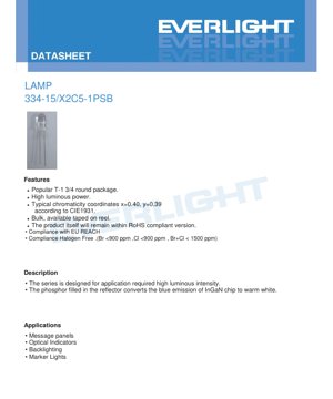
1. পণ্য সংক্ষিপ্ত বিবরণ
এই নথিটি একটি উচ্চ-কার্যক্ষমতা সম্পন্ন উষ্ণ সাদা LED ল্যাম্পের স্পেসিফিকেশন প্যারামিটার বিস্তারিতভাবে বর্ণনা করে। এই ডিভাইসটি InGaN সেমিকন্ডাক্টর চিপ ব্যবহার করে, যা ফ্লুরোসেন্ট ফসফর-পূর্ণ রিফ্লেক্টর কাপের সাথে মিলিত হয়ে নীল আলোকে উষ্ণ সাদা আলোতে রূপান্তরিত করে। এটি একটি সর্বজনীন T-1 3/4 বৃত্তাকার প্যাকেজে এনক্যাপসুলেট করা হয়েছে এবং উচ্চ লুমিনাস ফ্লাক্স প্রয়োজন এমন বিভিন্ন নির্দেশক আলো এবং আলোকসজ্জা অ্যাপ্লিকেশনের জন্য উপযুক্ত।
此LED的核心优势在于其高光功率和稳定的色彩特性,并定义了典型的色度坐标。其设计注重可靠性,并符合现代环保标准,包括RoHS、欧盟REACH以及无卤要求(Br <900 ppm, Cl <900 ppm, Br+Cl < 1500 ppm)。产品提供散装或编带包装,适用于自动化组装流程。
2. গভীর প্রযুক্তিগত প্যারামিটার বিশ্লেষণ
2.1 পরম সর্বোচ্চ রেটিং
দীর্ঘমেয়াদী নির্ভরযোগ্যতা নিশ্চিত করতে, ডিভাইসটি কঠোর সীমার মধ্যে কাজ করার জন্য ডিজাইন করা হয়েছে। অবিচ্ছিন্ন ফরওয়ার্ড কারেন্ট (IF) রেটিং হল 30 mA, পালস অবস্থার অধীনে (ডিউটি সাইকেল 1/10 @ 1 kHz) অনুমোদিত শীর্ষ ফরওয়ার্ড কারেন্ট (IFP) 100 mA। সর্বোচ্চ বিপরীত ভোল্টেজ (VR) 5 V। মোট শক্তি অপচয় (Pd) 110 mW অতিক্রম করবে না। অপারেটিং তাপমাত্রার পরিসীমা -40°C থেকে +85°C, স্টোরেজ তাপমাত্রার পরিসীমা -40°C থেকে +100°C। ডিভাইসটি 4 kV (হিউম্যান বডি মডেল) ইলেক্ট্রোস্ট্যাটিক ডিসচার্জ (ESD) সহ্য করতে পারে। সর্বোচ্চ সোল্ডারিং তাপমাত্রা 260°C, 5 সেকেন্ডের জন্য।
2.2 অপটোইলেকট্রিক বৈশিষ্ট্য
মূল কর্মক্ষমতা প্যারামিটারগুলি 25°C পরিবেষ্টিত তাপমাত্রা এবং 20 mA ফরোয়ার্ড কারেন্টের আদর্শ পরীক্ষার শর্তে পরিমাপ করা হয়।
- ফরোয়ার্ড ভোল্টেজ (VF):সর্বনিম্ন 2.8 V থেকে সর্বোচ্চ 3.6 V পর্যন্ত পরিসীমা। ড্রাইভার ডিজাইন এবং পাওয়ার সাপ্লাই নির্বাচনের জন্য এই প্যারামিটারটি অত্যন্ত গুরুত্বপূর্ণ।
- আলোক তীব্রতা (IV):সর্বনিম্ন আলোকিত তীব্রতা ২৮৫০ মিলিক্যান্ডেলা (mcd)। সাধারণ মান নির্দিষ্ট করা নেই, তবে সর্বোচ্চ মান ৭১৫০ mcd পর্যন্ত হতে পারে, যা নির্দেশ করে যে এই পণ্য সিরিজটি গ্রেডিং ব্যবস্থাপনার মাধ্যমে উল্লেখযোগ্য উজ্জ্বলতা বন্টন প্রদর্শন করে।
- দৃষ্টিকোণ (2θ1/2):সাধারণ অর্ধ-কোণ ৫০ ডিগ্রী, যা নির্গত আলোর কৌণিক বন্টনকে সংজ্ঞায়িত করে।
- ক্রোমাটিসিটি স্থানাঙ্ক:CIE 1931 স্ট্যান্ডার্ড অনুযায়ী, সাধারণ ক্রোমাটিসিটি পয়েন্ট স্থানাঙ্ক হল x=0.40, y=0.39। এটি সাদা আলোকে রঙের স্থানের উষ্ণ সাদা অঞ্চলে স্থাপন করে।
- জেনার সুরক্ষা:ডিভাইসটিতে বিপরীত ভোল্টেজ সুরক্ষার জন্য একটি জেনার ডায়োড সংহত করা হয়েছে, ৫ mA পরীক্ষা কারেন্টে এর সাধারণ বিপরীত ভোল্টেজ (VZ) হল ৫.২ V।
- বিপরীতমুখী কারেন্ট (IR):5 V বিপরীত বায়াস প্রয়োগ করলে সর্বোচ্চ বিপরীত লিক কারেন্ট 50 μA হয়।
3. গ্রেডিং সিস্টেমের বিবরণ
উজ্জ্বলতা, ফরোয়ার্ড ভোল্টেজ এবং রঙের সামঞ্জস্য নিশ্চিত করতে, LED গুলোকে নির্দিষ্ট গ্রেডে বাছাই করা হয়। এটি ডিজাইনারদের তাদের অ্যাপ্লিকেশনের সুনির্দিষ্ট প্রয়োজনীয়তা পূরণ করে এমন উপাদান নির্বাচন করতে সক্ষম করে।
3.1 লুমিনাস ইনটেনসিটি গ্রেডিং
20 mA তে পরিমাপকৃত লুমিনাস ইনটেনসিটির ভিত্তিতে, LED গুলোকে চারটি প্রধান গ্রেডে বিভক্ত করা হয়। প্রতিটি গ্রেডের ভিতরে সহনশীলতা হল ±10%।
- গ্রেড P:২৮৫০ এমসিডি (ন্যূনতম) থেকে ৩৬০০ এমসিডি (সর্বোচ্চ)
- গ্রেড Q:৩৬০০ এমসিডি থেকে ৪৫০০ এমসিডি
- গ্রেড R:৪৫০০ এমসিডি থেকে ৫৬৫০ এমসিডি
- গ্রেড S:৫৬৫০ এমসিডি থেকে ৭১৫০ এমসিডি
3.2 ফরওয়ার্ড ভোল্টেজ গ্রেডিং
ফরওয়ার্ড ভোল্টেজ সার্কিট ডিজাইন সহায়তার জন্য গ্রেড করা হয়, বিশেষ করে যেসব অ্যাপ্লিকেশনে ভোল্টেজ ড্রপ বা পাওয়ার খরচ সংবেদনশীল। পরিমাপের অনিশ্চয়তা ±০.১ ভি।
- গ্রেড ০:২.৮ V থেকে ৩.০ V
- গ্রেড ১:৩.০ V থেকে ৩.২ V
- গ্রেড ২:৩.২ V থেকে ৩.৪ V
- গ্রেড ৩:3.4 V থেকে 3.6 V
3.3 কালার গ্রেডিং (ক্রোমাটিসিটি)
রঙের আউটপুট কঠোরভাবে নিয়ন্ত্রিত হয় এবং CIE 1931 ক্রোমাটিসিটি ডায়াগ্রামে নির্দিষ্ট অঞ্চলে বিভক্ত করা হয়। সংজ্ঞায়িত রঙ গ্রেডগুলি হল D1, D2, E1, E2, F1 এবং F2। এই গ্রুপগুলি উষ্ণ সাদা আলোর বর্ণালীর মধ্যে বিভিন্ন চতুর্ভুজাকার অঞ্চল উপস্থাপন করে, যেখানে F1/F2 সবচেয়ে উষ্ণ (সর্বনিম্ন সংশ্লিষ্ট রঙের তাপমাত্রা), এবং D1/D2 তুলনামূলকভাবে শীতল। ক্রোমাটিসিটি স্থানাঙ্কের পরিমাপের অনিশ্চয়তা হল ±0.01। স্পেসিফিকেশন শীট এই গ্রেডগুলিকে একটি নির্বাচন গ্রুপে (গ্রুপ 1: D1+D2+E1+E2+F1+F2) শ্রেণীবদ্ধ করে, যা নির্দেশ করে যে পণ্য সিরিজটি এই সমস্ত রঙ গ্রেড সরবরাহ করে।
4. পারফরম্যান্স কার্ভ বিশ্লেষণ
স্পেসিফিকেশন শীটে বেশ কয়েকটি বৈশিষ্ট্য কার্ভ রয়েছে যা বিভিন্ন অবস্থার অধীনে ডিভাইসের আচরণ চিত্রিত করে।
4.1 আপেক্ষিক তীব্রতা বনাম তরঙ্গদৈর্ঘ্য
এই বর্ণালী বন্টন বক্ররেখাটি বিভিন্ন তরঙ্গদৈর্ঘ্যে নির্গত আলোর আপেক্ষিক তীব্রতা প্রদর্শন করে। উষ্ণ সাদা LED-এর জন্য, বক্ররেখাটি সাধারণত নীল অঞ্চলে (InGaN চিপ থেকে) একটি প্রধান শিখর এবং হলুদ/লাল অঞ্চলে (ফসফর রূপান্তর থেকে) একটি বিস্তৃত শিখর বা মঞ্চ প্রদর্শন করে। সঠিক আকৃতি LED-এর রঙ রেন্ডারিং বৈশিষ্ট্য নির্ধারণ করে।
4.2 নির্দেশক চিত্র
নির্দেশিক বক্ররেখাটি আপেক্ষিক তীব্রতা এবং বিকিরণ কোণের সম্পর্ক অঙ্কন করে, যা 50 ডিগ্রির সাধারণ দৃষ্টিকোণকে স্বজ্ঞাতভাবে নিশ্চিত করে। এটি দেখায় কেন্দ্রীয় অক্ষ (0 ডিগ্রি) থেকে দূরে সরে যাওয়ার সাথে সাথে আলোর তীব্রতা কীভাবে হ্রাস পায়।
4.3 ফরোয়ার্ড কারেন্ট বনাম ফরোয়ার্ড ভোল্টেজ (I-V কার্ভ)
এই মৌলিক বক্ররেখাটি ডায়োডের কারেন্ট এবং ভোল্টেজের মধ্যে সূচকীয় সম্পর্ক প্রদর্শন করে। অপারেটিং পয়েন্ট নির্ধারণ এবং কারেন্ট-সীমাবদ্ধ সার্কিট বা ধ্রুব-কারেন্ট ড্রাইভার ডিজাইনের জন্য এটি অত্যন্ত গুরুত্বপূর্ণ।
4.4 আপেক্ষিক তীব্রতা বনাম ফরোয়ার্ড কারেন্ট
এই গ্রাফটি দেখায় কিভাবে আলোর আউটপুট (আপেক্ষিক তীব্রতা) ফরওয়ার্ড কারেন্ট বৃদ্ধির সাথে বৃদ্ধি পায়। একটি নির্দিষ্ট পরিসরে এটি সাধারণত রৈখিক হয়, কিন্তু উচ্চতর কারেন্টে তাপীয় প্রভাব এবং দক্ষতা হ্রাসের কারণে এটি সম্পৃক্ত হতে পারে।
4.5 ক্রোমাটিসিটি স্থানাঙ্ক বনাম ফরোয়ার্ড কারেন্ট
রঙের জন্য কঠোর প্রয়োজনীয়তা সম্পন্ন অ্যাপ্লিকেশনের জন্য এই কার্ভটি অত্যন্ত গুরুত্বপূর্ণ। এটি দেখায় কিভাবে কালার পয়েন্ট (x, y কোঅর্ডিনেট) ড্রাইভিং কারেন্টের পরিবর্তনের সাথে সরে যায়। আদর্শ বৈশিষ্ট্য হল বিভিন্ন কারেন্ট স্তরে কালার পয়েন্টের স্থিতিশীলতা বজায় রাখা।
4.6 ফরোয়ার্ড কারেন্ট বনাম পরিবেষ্টন তাপমাত্রা
এই ডিরেটিং কার্ভটি পরিবেষ্টিত তাপমাত্রা বৃদ্ধির সাথে সর্বাধিক অনুমোদিত ফরওয়ার্ড কারেন্টের পরিবর্তন নির্দেশ করে। অতিরিক্ত গরম হওয়া রোধ করতে এবং নির্ভরযোগ্যতা নিশ্চিত করতে, উচ্চ তাপমাত্রায় কাজ করার সময় সর্বোচ্চ কারেন্ট হ্রাস করতে হবে।
5. যান্ত্রিক ও প্যাকেজিং তথ্য
5.1 প্যাকেজ মাত্রা
LED টি স্ট্যান্ডার্ড T-1 3/4 বৃত্তাকার প্যাকেজে ব্যবহৃত হয়। প্রধান মাত্রার বিবরণে অন্তর্ভুক্ত:
- সকল মাত্রার একক মিলিমিটার (mm)।
- বিশেষভাবে উল্লেখ না করা পর্যন্ত, সাধারণ সহনশীলতা হল ±0.25 mm।
- পিন পিচ প্যাকেজ বডি থেকে পিন বের হওয়ার অবস্থানে পরিমাপ করা হয়।
- ফ্ল্যাঞ্জের নিচে রজন এর সর্বোচ্চ প্রোট্রুশন হল 1.5 mm।
6. সোল্ডারিং ও অ্যাসেম্বলি নির্দেশিকা
সঠিক হ্যান্ডলিং LED এর কর্মক্ষমতা এবং নির্ভরযোগ্যতা বজায় রাখার জন্য অত্যন্ত গুরুত্বপূর্ণ।
6.1 পিন গঠন
- বাঁকানো বিন্দুটি ইপোক্সি ল্যাম্প বডির নীচ থেকে কমপক্ষে 3 মিমি দূরত্বে হওয়া উচিত।
- 在সোল্ডারিংউপাদান বসানোর আগে পিন ফরম করুন।
- বাঁকানোর প্রক্রিয়ায় LED প্যাকেজের উপর চাপ প্রয়োগ এড়িয়ে চলুন, অন্যথায় অভ্যন্তরীণ সংযোগ ক্ষতিগ্রস্ত হতে পারে বা ইপোক্সি ফাটল দেখা দিতে পারে।
- কক্ষ তাপমাত্রায় পিন কাটুন। উচ্চ তাপমাত্রায় কাটলে ব্যর্থতা ঘটতে পারে।
- ইনস্টলেশন স্ট্রেস এড়াতে PCB গর্ত এবং LED পিনের নিখুঁত সংযোগ নিশ্চিত করুন।
6.2 সংরক্ষণ শর্ত
- প্রস্তাবিত স্টোরেজ শর্ত: ≤30°C, আপেক্ষিক আর্দ্রতা ≤70%।
- এই শর্তে, শিপমেন্টের তারিখ থেকে শেল্ফ লাইফ 3 মাস।
- দীর্ঘ সময়ের জন্য (সর্বোচ্চ 1 বছর) সংরক্ষণের প্রয়োজন হলে, ডেসিক্যান্ট সহ নাইট্রোজেন সিলড কন্টেইনার ব্যবহার করুন।
- ঘনীভবন রোধ করতে আর্দ্র পরিবেশে তাপমাত্রার আকস্মিক পরিবর্তন এড়িয়ে চলুন।
6.3 সোল্ডারিং প্রক্রিয়া
- সোল্ডার পয়েন্ট থেকে এপোক্সি ল্যাম্প বডির দূরত্ব 3 মিমি এর বেশি রাখুন।
- শুধুমাত্র লিড ফ্রেমের সংযোগ স্ট্রিপের গোড়ায় সোল্ডার করার পরামর্শ দেওয়া হয়।
- সর্বোচ্চ 260°C সোল্ডারিং তাপমাত্রা 5 সেকেন্ডের জন্য বজায় রাখার নিয়ম মেনে চলুন।
৭. প্যাকেজিং ও অর্ডার তথ্য
৭.১ প্যাকেজিং স্পেসিফিকেশন
LED গুলি ইলেক্ট্রোস্ট্যাটিক এবং আর্দ্রতা প্রতিরোধী প্যাকেজিং ব্যবহার করে।
- প্রাথমিক প্যাকেজিং:ইলেক্ট্রোস্ট্যাটিক প্রতিরোধী ব্যাগ।
- পরিমাণ:প্রতি ব্যাগে 200 থেকে 500 পিস।
- মাধ্যমিক প্যাকেজিং:৫টি ব্যাগ একটি অভ্যন্তরীণ বাক্সে রাখা হয়।
- তৃতীয় স্তরের প্যাকেজিং:১০টি অভ্যন্তরীণ বাক্স একটি বহিরাগত কার্টনে ভরা হয়।
৭.২ লেবেল নির্দেশনা
প্যাকেজিংয়ের লেবেলে গুরুত্বপূর্ণ তথ্য রয়েছে:
- CPN:কাস্টমার পার্ট নম্বর।
- P/N:প্রস্তুতকারকের পার্ট নম্বর।
- QTY:প্যাকেজের ভিতরে পরিমাণ।
- CAT:লুমিনাস ইনটেনসিটি এবং ফরওয়ার্ড ভোল্টেজ গ্রেড কম্বিনেশন কোড।
- HUE:রঙের গ্রেড কোড (যেমন, D1, F2)।
- REF:তথ্যসূত্র।
- LOT No:উৎপাদন ব্যাচ নম্বর, ট্রেস করার জন্য ব্যবহৃত।
৭.৩ মডেল নামকরণ নিয়ম
পার্ট নম্বর একটি কাঠামোগত বিন্যাস অনুসরণ করে:334-15/X2C5-□ □ □ □। খালি স্থান (□) প্রয়োজনীয় নির্বাচনের সাথে মিলে যায়রঙের গ্রুপ, 、আলোকিত তীব্রতা স্তর和ফরওয়ার্ড ভোল্টেজ গ্রুপ
এর নির্দিষ্ট কোড। এটি ব্যবহারকারীদের তাদের প্রয়োগের জন্য প্রয়োজনীয় সঠিক কর্মক্ষমতা বৈশিষ্ট্য নির্দিষ্ট করতে সক্ষম করে।
8. প্রয়োগের সুপারিশ ও ডিজাইন বিবেচনা
8.1 সাধারণ প্রয়োগ
- এই উচ্চ উজ্জ্বলতা উষ্ণ সাদা LED বিশেষভাবে উপযুক্ত:তথ্য এবং নির্দেশিকা প্যানেল:
- উচ্চ কনট্রাস্ট এবং পাঠযোগ্যতা প্রয়োজন এমন ক্ষেত্র।অপটিক্যাল স্ট্যাটাস ইন্ডিকেটর:
- কনজিউমার ইলেকট্রনিক্স, শিল্প সরঞ্জাম এবং অটোমোটিভ ড্যাশবোর্ডে ব্যবহৃত হয়।ব্যাকলাইট:
- ছোট এলসিডি ডিসপ্লে, মেমব্রেন সুইচ বা সজ্জা প্যানেলের জন্য ব্যবহৃত হয়।মার্কিং এবং পজিশন লাইট:
আলোকসজ্জা বা সংকেত নির্দেশনা প্রদান করে।
- 8.2 ডিজাইন বিবেচ্য বিষয়কারেন্ট ড্রাইভ:Fসর্বদা একটি কনস্ট্যান্ট কারেন্ট ড্রাইভার বা ফরওয়ার্ড ভোল্টেজ বিন (V
- ) এবং পাওয়ার সাপ্লাই ভোল্টেজের উপর ভিত্তি করে উপযুক্ত কারেন্ট-লিমিটিং রেজিস্টর ব্যবহার করুন। কখনই পরম সর্বোচ্চ রেটিং অতিক্রম করবেন না।তাপ ব্যবস্থাপনা:
- অপেক্ষাকৃত কম পাওয়ার ডিসিপেশন (110 mW) সত্ত্বেও, উচ্চ পরিবেষ্টিত তাপমাত্রায়, বিশেষ করে সর্বোচ্চ কারেন্ট ড্রাইভের কাছাকাছি চালনা করার সময়, পর্যাপ্ত তাপ অপসারণ বা বায়ুপ্রবাহ নিশ্চিত করুন। ফরওয়ার্ড কারেন্ট বনাম পরিবেষ্টিত তাপমাত্রা ডিরেটিং কার্ভ দেখুন।অপটিক্যাল ডিজাইন:
- 50-ডিগ্রি ভিউ অ্যাঙ্গেল বেশ প্রশস্ত বিম প্রদান করে। আলোক রশ্মি ফোকাস করার জন্য সেকেন্ডারি অপটিক্যাল উপাদান (লেন্স) প্রয়োজন হতে পারে।ESD সুরক্ষা:
- ডিভাইসটিতে 4kV HBM রেটিং থাকা সত্ত্বেও, অ্যাসেম্বলি প্রক্রিয়ায় স্ট্যান্ডার্ড ESD হ্যান্ডলিং সতর্কতা অনুসরণ করা উচিত।রঙের সামঞ্জস্য:
রঙের চেহারা সমান রাখার প্রয়োজন এমন প্রয়োগের জন্য, কঠোর রঙের গ্রেড (HUE) নির্দিষ্ট করা উচিত এবং অ্যারেতে থাকা সমস্ত LED যেন একই বা সংলগ্ন গ্রেড থেকে আসে তা নিশ্চিত করতে হবে।
9. প্রযুক্তিগত তুলনা ও পার্থক্য
এই LED-এর প্রধান পার্থক্য হল এটি ক্লাসিক এবং ব্যাপকভাবে গৃহীত T-1 3/4 প্যাকেজকে উষ্ণ সাদা আলো নির্গমনের জন্য উচ্চ আলোকিত তীব্রতার সাথে একত্রিত করে। ছোট SMD LED-এর তুলনায়, থ্রু-হোল ডিজাইন প্রোটোটাইপিং, ম্যানুয়াল অ্যাসেম্বলি বা উচ্চতর একক-বিন্দু উজ্জ্বলতা প্রয়োজন এমন অ্যাপ্লিকেশনগুলিতে সুবিধা প্রদান করতে পারে। বিপরীত ভোল্টেজ সুরক্ষার জন্য জেনার ডায়োড ইন্টিগ্রেশন একটি উল্লেখযোগ্য বৈশিষ্ট্য, যা বিপরীত ভোল্টেজ স্পাইক ঘটতে পারে এমন সার্কিট ডিজাইনে দৃঢ়তা বৃদ্ধি করে। বিস্তারিত মাল্টি-প্যারামিটার বিনিং সিস্টেম (তীব্রতা, ভোল্টেজ, রঙ) ডিজাইনারদের চূড়ান্ত পণ্যের কর্মক্ষমতা এবং সামঞ্জস্যের উপর উচ্চ মাত্রার নিয়ন্ত্রণ প্রদান করে, যা বাল্ক উৎপাদনের জন্য অত্যন্ত গুরুত্বপূর্ণ।
10. প্রায়শই জিজ্ঞাসিত প্রশ্ন (প্রযুক্তিগত স্পেসিফিকেশনের উপর ভিত্তি করে)
10.1 কোন ড্রাইভার সার্কিট সুপারিশ করা হয়?মৌলিক সূচক আলোর ব্যবহারের জন্য, একটি সাধারণ সিরিজ রোধই যথেষ্ট। গণনার সূত্র হল: R = (Vবিদ্যুৎ সরবরাহF- VF) / IF। সর্বোচ্চ V সহ রেঞ্জ ব্যবহার করুন
(উদাহরণস্বরূপ, বিন 3 হল 3.6V) যাতে সবচেয়ে খারাপ অবস্থায় কারেন্ট 20mA-এর বেশি না হয়। সর্বোত্তম স্থিতিশীলতা এবং দক্ষতার জন্য, বিশেষ করে অ্যারেতে বা উচ্চতর কারেন্ট ব্যবহার করার সময়, একটি কনস্ট্যান্ট কারেন্ট ড্রাইভার ব্যবহারের সুপারিশ করা হয়।
10.2 তাপমাত্রা কীভাবে কর্মক্ষমতা প্রভাবিত করে?
পরিবেষ্টিত তাপমাত্রা বৃদ্ধির সাথে, LED-এর ফরওয়ার্ড ভোল্টেজ সামান্য হ্রাস পায়, কিন্তু এর অভ্যন্তরীণ দক্ষতা কমে যেতে পারে, যার ফলে একই কারেন্টে আলোর আউটপুট হ্রাস পায়। আরও গুরুত্বপূর্ণভাবে, অত্যধিক উচ্চ তাপমাত্রা LED-এর অপারেশনাল জীবনকাল হ্রাস করে। ফরওয়ার্ড কারেন্ট বনাম পরিবেষ্টিত তাপমাত্রা ডিরেটিং কার্ভ অবশ্যই উল্লেখ করা উচিত এবং উপযুক্ত তাপীয় নকশার মাধ্যমে জংশন তাপমাত্রা নিরাপদ সীমার মধ্যে রাখা নিশ্চিত করা উচিত।
10.3 আমি কি এটি কালার মিক্সিং অ্যাপ্লিকেশনের জন্য ব্যবহার করতে পারি?
এটি একটি ফসফর-রূপান্তরিত উষ্ণ সাদা LED, একরঙা LED নয়। এটি RGB মিশ্রণের জন্য ডিজাইন করা হয়নি। মিশ্রণের জন্য নির্দিষ্ট লাল, সবুজ, নীল (RGB) LED ব্যবহার করা উচিত।
10.4 জেনার ভোল্টেজ স্পেসিফিকেশনের উদ্দেশ্য কী?ZLED-এর উভয় প্রান্তে সুরক্ষার জন্য জেনার ডায়োড সংযুক্ত করা হয়েছে। যদি প্রায় 5.2V-এর বেশি বিপরীত ভোল্টেজ দুর্ঘটনাবশত প্রয়োগ করা হয়, জেনার ডায়োড সক্রিয় হয়ে ভোল্টেজ ক্ল্যাম্প করবে, যার ফলে LED জাংশন ক্ষতির হাত থেকে রক্ষা পেতে পারে। জেনার বিপরীত কারেন্ট (I
) 100 mA রেটিংটি এই সুরক্ষামূলক ভূমিকায় এর কারেন্ট পরিচালনার ক্ষমতা নির্দেশ করে।
11. ডিজাইন ও ব্যবহার কেস স্টাডি
দৃশ্যকল্প: একটি শিল্প সরঞ্জামের জন্য উচ্চ দৃশ্যমানতা সম্পন্ন অবস্থা নির্দেশক ডিজাইন করা।Fএকজন ইঞ্জিনিয়ারকে একটি উজ্জ্বল, নির্ভরযোগ্য অবস্থা আলো ডিজাইন করতে হবে যা ভালো আলোকিত কারখানা পরিবেশে চলমান একটি মেশিনের জন্য। আলোটি সব কোণ থেকে স্পষ্টভাবে দৃশ্যমান হতে হবে এবং একটি উষ্ণ, স্পষ্ট রং থাকতে হবে। তারা এই LED-এর গ্রেড S (সর্বোচ্চ তীব্রতা, 5650-7150 mcd) এবং রং গ্রেড F1/F2 (উষ্ণ চেহারার জন্য) নির্বাচন করে। তারা একটি 12V পাওয়ার রেল সহ একটি PCB ডিজাইন করে। সর্বোচ্চ VF3.6V এবং লক্ষ্য I
20mA, তারা সিরিজ রেজিস্টর গণনা করে: R = (12V - 3.6V) / 0.02A = 420Ω। একটি স্ট্যান্ডার্ড 430Ω, 1/4W রেজিস্টর নির্বাচন করা হয়। তারা অ্যাসেম্বলি নির্দেশিকা অনুসরণ করে, ঢোকানোর আগে লিডগুলিকে বডি থেকে 4mm দূরে বাঁকায়। চূড়ান্ত ইন্ডিকেটরটি পরিবেষ্টিত আলোতেও উৎকৃষ্ট দৃশ্যমানতা প্রদান করে এবং সামঞ্জস্যপূর্ণ বিনিং উৎপাদন লাইনে সমস্ত ইউনিটের অভিন্ন চেহারা নিশ্চিত করে।
12. কার্যপ্রণালীর সংক্ষিপ্ত পরিচয়
এই LED-টি সেমিকন্ডাক্টর ইলেক্ট্রোলুমিনেসেন্স নীতির উপর কাজ করে। এর মূল হল একটি InGaN চিপ। যখন ফরওয়ার্ড ভোল্টেজ প্রয়োগ করা হয়, তখন ইলেকট্রন এবং হোলগুলি চিপের সক্রিয় অঞ্চলে পুনর্মিলিত হয় এবং ফোটন আকারে শক্তি মুক্ত করে। InGaN খাদের নির্দিষ্ট উপাদান এই নির্গত আলোকে নীল তরঙ্গদৈর্ঘ্য পরিসরে স্থাপন করে। সাদা আলো তৈরি করতে, নীল আলোকে রিফ্লেক্টর কাপের ভিতরের ফসফর আবরণের দিকে পরিচালিত করা হয়। ফসফর কিছু নীল ফোটন শোষণ করে এবং দীর্ঘতর হলুদ ও লাল তরঙ্গদৈর্ঘ্যে পুনরায় আলো নির্গত করে। অবশিষ্ট নীল আলো ফসফর-রূপান্তরিত হলুদ/লাল আলোর সাথে মিশে যায়, যা মানব চোখ দ্বারা উষ্ণ সাদা আলো হিসাবে অনুভূত হয়। সঠিক বর্ণ (সম্পর্কিত রঙের তাপমাত্রা) ফসফরের উপাদান এবং ঘনত্ব দ্বারা নির্ধারিত হয়।
13. প্রযুক্তিগত প্রবণতা ও পটভূমি
LED স্পেসিফিকেশন পরিভাষার বিস্তারিত ব্যাখ্যা
LED প্রযুক্তিগত পরিভাষার সম্পূর্ণ ব্যাখ্যা
এক. আলোক-বৈদ্যুতিক কর্মক্ষমতার মূল সূচক
| পরিভাষা | একক/প্রকাশ | সাধারণ ব্যাখ্যা | কেন গুরুত্বপূর্ণ |
|---|---|---|---|
| আলোকিক কার্যকারিতা (Luminous Efficacy) | lm/W (লুমেন/ওয়াট) | প্রতি ওয়াট বিদ্যুৎ শক্তি থেকে নির্গত আলোক প্রবাহ, যত বেশি হবে শক্তি সাশ্রয় তত বেশি। | সরাসরি আলোর যন্ত্রের শক্তি দক্ষতা স্তর এবং বিদ্যুৎ বিলের খরচ নির্ধারণ করে। |
| আলোক প্রবাহ (Luminous Flux) | lm (লুমেন) | আলোর উৎস থেকে নির্গত মোট আলোর পরিমাণ, সাধারণভাবে "উজ্জ্বলতা" নামে পরিচিত। | ল্যাম্পটি যথেষ্ট উজ্জ্বল কিনা তা নির্ধারণ করে। |
| আলোক নির্গমন কোণ (Viewing Angle) | ° (ডিগ্রী), যেমন 120° | আলোর তীব্রতা অর্ধেক কমে গেলে যে কোণ তৈরি হয়, তা আলোর রশ্মির প্রস্থ নির্ধারণ করে। | আলোকিত এলাকার পরিসর এবং সমতা প্রভাবিত করে। |
| বর্ণ তাপমাত্রা (CCT) | K (কেলভিন), যেমন 2700K/6500K | আলোর রঙের উষ্ণতা বা শীতলতা; কম মান হলুদ/উষ্ণ, বেশি মান সাদা/শীতল নির্দেশ করে। | আলোর পরিবেশ এবং প্রযোজ্য পরিস্থিতি নির্ধারণ করে। |
| রঙ রেন্ডারিং সূচক (CRI / Ra) | এককহীন, ০–১০০ | আলোর উৎস দ্বারা বস্তুর প্রকৃত রঙ পুনরুৎপাদনের ক্ষমতা, Ra≥৮০ উত্তম। | রঙের বাস্তবতাকে প্রভাবিত করে, শপিং মল, আর্ট গ্যালারির মতো উচ্চ চাহিদাসম্পন্ন স্থানে ব্যবহৃত হয়। |
| রঙ সহনশীলতা (SDCM) | ম্যাকঅ্যাডাম উপবৃত্ত ধাপ সংখ্যা, যেমন "5-step" | রঙের সামঞ্জস্যের পরিমাণগত সূচক, পদক্ষেপ যত কম রঙ তত বেশি সামঞ্জস্যপূর্ণ। | একই ব্যাচের আলোর যন্ত্রের রঙে কোন পার্থক্য নেই তা নিশ্চিত করা। |
| Dominant Wavelength | nm (ন্যানোমিটার), যেমন 620nm (লাল) | রঙিন LED রঙের সাথে সম্পর্কিত তরঙ্গদৈর্ঘ্যের মান। | লাল, হলুদ, সবুজ ইত্যাদি একরঙা LED-এর রঙের আভা নির্ধারণ করে। |
| বর্ণালী বণ্টন (Spectral Distribution) | তরঙ্গদৈর্ঘ্য বনাম তীব্রতা বক্ররেখা | LED থেকে নির্গত আলোর বিভিন্ন তরঙ্গদৈর্ঘ্যে তীব্রতা বণ্টন প্রদর্শন করে। | বর্ণ প্রতিপাদন ও রঙের গুণমানকে প্রভাবিত করে। |
দুই. বৈদ্যুতিক প্যারামিটার
| পরিভাষা | প্রতীক | সাধারণ ব্যাখ্যা | নকশা বিবেচ্য বিষয় |
|---|---|---|---|
| ফরওয়ার্ড ভোল্টেজ (Forward Voltage) | Vf | LED জ্বালানোর জন্য প্রয়োজনীয় সর্বনিম্ন ভোল্টেজ, একপ্রকার "চালু হওয়ার প্রান্তিক মান"। | ড্রাইভার পাওয়ার সাপ্লাই ভোল্টেজ ≥ Vf হতে হবে, একাধিক LED সিরিজে সংযুক্ত হলে ভোল্টেজ যোগ হয়। |
| ফরওয়ার্ড কারেন্ট (Forward Current) | If | LED কে স্বাভাবিকভাবে আলোকিত করার জন্য প্রয়োজনীয় কারেন্টের মান। | সাধারণত কনস্ট্যান্ট কারেন্ট ড্রাইভ ব্যবহার করা হয়, কারেন্ট উজ্জ্বলতা ও আয়ু নির্ধারণ করে। |
| সর্বোচ্চ পালস কারেন্ট (Pulse Current) | Ifp | স্বল্প সময়ের জন্য সহনীয় পিক কারেন্ট, ডিমিং বা ফ্ল্যাশিংয়ের জন্য ব্যবহৃত হয়। | পালস প্রস্থ এবং ডিউটি সাইকেল কঠোরভাবে নিয়ন্ত্রণ করতে হবে, অন্যথায় অতিরিক্ত গরম হয়ে ক্ষতি হতে পারে। |
| Reverse Voltage | Vr | LED দ্বারা সহনীয় সর্বোচ্চ বিপরীত ভোল্টেজ, অতিক্রম করলে ব্রেকডাউন হতে পারে। | সার্কিটে বিপরীত সংযোগ বা ভোল্টেজ স্পাইক প্রতিরোধ করতে হবে। |
| Thermal Resistance | Rth (°C/W) | চিপ থেকে সোল্ডার পয়েন্টে তাপ প্রবাহের প্রতিরোধ, মান যত কম হবে তাপ অপসারণ তত ভালো। | উচ্চ তাপীয় রোধের জন্য শক্তিশালী তাপ অপসারণ নকশা প্রয়োজন, নতুবা জংশন তাপমাত্রা বৃদ্ধি পায়। |
| ইলেক্ট্রোস্ট্যাটিক ডিসচার্জ ইমিউনিটি (ESD Immunity) | V (HBM), যেমন 1000V | ইলেক্ট্রোস্ট্যাটিক শক প্রতিরোধের ক্ষমতা, মান যত বেশি হবে ইলেক্ট্রোস্ট্যাটিক ডিসচার্জ দ্বারা ক্ষতিগ্রস্ত হওয়ার সম্ভাবনা তত কম। | উৎপাদন প্রক্রিয়ায় স্থির বিদ্যুৎ প্রতিরোধী ব্যবস্থা গ্রহণ করতে হবে, বিশেষ করে উচ্চ সংবেদনশীল LED-এর ক্ষেত্রে। |
তিন. তাপ ব্যবস্থাপনা ও নির্ভরযোগ্যতা
| পরিভাষা | মূল সূচক | সাধারণ ব্যাখ্যা | প্রভাব |
|---|---|---|---|
| জাংশন তাপমাত্রা (Junction Temperature) | Tj (°C) | LED চিপের অভ্যন্তরীণ প্রকৃত অপারেটিং তাপমাত্রা। | প্রতি 10°C হ্রাসে, আয়ু দ্বিগুণ হতে পারে; অত্যধিক তাপমাত্রা আলোক ক্ষয় এবং বর্ণ পরিবর্তনের কারণ হয়। |
| Lumen Depreciation | L70 / L80 (ঘন্টা) | উজ্জ্বলতা প্রাথমিক মানের 70% বা 80% এ পৌঁছাতে প্রয়োজনীয় সময়। | LED-এর "সেবা জীবন" সরাসরি সংজ্ঞায়িত করে। |
| লুমেন রক্ষণাবেক্ষণ হার (Lumen Maintenance) | % (যেমন 70%) | কিছু সময় ব্যবহারের পর অবশিষ্ট উজ্জ্বলতার শতাংশ। | দীর্ঘমেয়াদী ব্যবহারের পর উজ্জ্বলতা ধরে রাখার ক্ষমতা চিহ্নিত করে। |
| রঙের সরণ (Color Shift) | Δu′v′ অথবা ম্যাকঅ্যাডাম উপবৃত্ত | ব্যবহারের সময় রঙের পরিবর্তনের মাত্রা। | আলোক দৃশ্যের রঙের সামঞ্জস্যকে প্রভাবিত করে। |
| তাপীয় বার্ধক্য (Thermal Aging) | উপাদানের কার্যকারিতা হ্রাস | দীর্ঘমেয়াদী উচ্চ তাপমাত্রার কারণে এনক্যাপসুলেশন উপাদানের অবনতি। | উজ্জ্বলতা হ্রাস, রঙের পরিবর্তন বা ওপেন সার্কিট ব্যর্থতার কারণ হতে পারে। |
চার, প্যাকেজিং ও উপকরণ
| পরিভাষা | সাধারণ প্রকার | সাধারণ ব্যাখ্যা | বৈশিষ্ট্য এবং প্রয়োগ |
|---|---|---|---|
| এনক্যাপসুলেশন প্রকার | EMC, PPA, সিরামিক | চিপ সুরক্ষা এবং অপটিক্যাল, থার্মাল ইন্টারফেস প্রদানকারী আবরণ উপকরণ। | EMC তাপ প্রতিরোধী, কম খরচ; সিরামিক তাপ অপসারণে উৎকৃষ্ট, দীর্ঘ আয়ু। |
| চিপ কাঠামো | ফরওয়ার্ড-মাউন্ট, ফ্লিপ চিপ | চিপ ইলেক্ট্রোড বিন্যাস পদ্ধতি। | ফ্লিপ চিপ তাপ অপসারণ ভাল, আলোক দক্ষতা বেশি, উচ্চ শক্তির জন্য উপযুক্ত। |
| ফসফর আবরণ | YAG, সিলিকেট, নাইট্রাইড | নীল আলোর চিপের উপর প্রলেপ দেওয়া হয়, আংশিকভাবে হলুদ/লাল আলোতে রূপান্তরিত হয় এবং সাদা আলোতে মিশ্রিত হয়। | বিভিন্ন ফসফর আলোর দক্ষতা, রঙের তাপমাত্রা এবং রঙ রেন্ডারিংকে প্রভাবিত করে। |
| লেন্স/অপটিক্যাল ডিজাইন | সমতল, মাইক্রোলেন্স, টোটাল ইন্টার্নাল রিফ্লেকশন | প্যাকেজিং পৃষ্ঠের অপটিক্যাল কাঠামো, আলোর বন্টন নিয়ন্ত্রণ করে। | আলোক নির্গমন কোণ এবং আলোক বণ্টন বক্ররেখা নির্ধারণ করে। |
পাঁচ, গুণমান নিয়ন্ত্রণ ও গ্রেডিং
| পরিভাষা | গ্রেডিং বিষয়বস্তু | সাধারণ ব্যাখ্যা | উদ্দেশ্য |
|---|---|---|---|
| লুমিনাস ফ্লাক্স গ্রেডিং | কোড যেমন 2G, 2H | উজ্জ্বলতার উচ্চ-নিম্ন অনুযায়ী গ্রুপ করা, প্রতিটি গ্রুপের ন্যূনতম/সর্বোচ্চ লুমেন মান রয়েছে। | একই ব্যাচের পণ্যের উজ্জ্বলতা সামঞ্জস্যপূর্ণ তা নিশ্চিত করুন। |
| ভোল্টেজ গ্রেডিং | কোড যেমন 6W, 6X | ফরওয়ার্ড ভোল্টেজ রেঞ্জ অনুযায়ী গ্রুপ করা। | ড্রাইভার পাওয়ার সাপ্লাইয়ের সাথে মিলে যাওয়া সহজ করতে এবং সিস্টেমের দক্ষতা বৃদ্ধি করতে। |
| রঙের পার্থক্য অনুযায়ী শ্রেণীবিভাগ | 5-step MacAdam ellipse | রঙের স্থানাঙ্ক অনুযায়ী গ্রুপিং, নিশ্চিত করে রঙ অত্যন্ত সীমিত পরিসরে অবস্থান করে। | রঙের সামঞ্জস্য নিশ্চিত করা, একই লাইট ফিক্সচারের মধ্যে রঙের অসামঞ্জস্যতা এড়ানো। |
| কালার টেম্পারেচার শ্রেণীবিভাগ | 2700K, 3000K ইত্যাদি | রঙের তাপমাত্রা অনুযায়ী গ্রুপ করা হয়েছে, প্রতিটি গ্রুপের জন্য সংশ্লিষ্ট স্থানাঙ্ক পরিসীমা রয়েছে। | বিভিন্ন দৃশ্যের রঙের তাপমাত্রার চাহিদা পূরণ করে। |
ছয়, পরীক্ষণ ও প্রত্যয়ন
| পরিভাষা | স্ট্যান্ডার্ড/পরীক্ষা | সাধারণ ব্যাখ্যা | তাৎপর্য |
|---|---|---|---|
| LM-80 | লুমেন রক্ষণাবেক্ষণ পরীক্ষা | ধ্রুব তাপমাত্রার অবস্থায় দীর্ঘমেয়াদী আলোকসজ্জার মাধ্যমে উজ্জ্বলতা হ্রাসের তথ্য রেকর্ড করা হয়। | LED-এর আয়ুষ্কাল অনুমান করতে ব্যবহৃত হয় (TM-21-এর সাথে সমন্বয় করে)। |
| TM-21 | আয়ুষ্কাল অনুমান প্রমিতকরণ | LM-80 তথ্যের ভিত্তিতে বাস্তব ব্যবহারের শর্তে আয়ুষ্কাল অনুমান করা। | বৈজ্ঞানিক জীবনকাল পূর্বাভাস প্রদান করা। |
| IESNA স্ট্যান্ডার্ড | ইলুমিনেটিং ইঞ্জিনিয়ারিং সোসাইটি স্ট্যান্ডার্ড | অপটিক্যাল, বৈদ্যুতিক, তাপীয় পরীক্ষা পদ্ধতি অন্তর্ভুক্ত করে। | শিল্প-স্বীকৃত পরীক্ষার ভিত্তি। |
| RoHS / REACH | পরিবেশগত প্রত্যয়ন | পণ্যটি ক্ষতিকারক পদার্থ (যেমন সীসা, পারদ) মুক্ত তা নিশ্চিত করা। | আন্তর্জাতিক বাজারে প্রবেশের শর্তাবলী। |
| ENERGY STAR / DLC | শক্তি দক্ষতা প্রত্যয়ন | আলোকসজ্জা পণ্যের জন্য শক্তি দক্ষতা ও কার্যকারিতা প্রত্যয়ন। | প্রায়শই সরকারি ক্রয়, ভর্তুকি প্রকল্পে ব্যবহৃত হয়, বাজার প্রতিযোগিতা বৃদ্ধি করে। |