Table of Contents
- 1. Product Overview
- 2. Technical Specifications and Deep Objective Interpretation
- 2.1 Absolute Maximum Ratings
- 2.2 Electrical Characteristics
- 2.2.1 Input Characteristics
- 2.2.2 Output and Transfer Characteristics
- 2.3 Switching Characteristics
- 3. Performance Curve Analysis
- 4. Mechanical and Package Information
- 4.1 Pin Configuration and Function
- 4.2 Package Dimensions and Recommended Pad Layout
- 5. Soldering and Assembly Guidelines
- 6. Packaging and Ordering Information
- 6.1 Ordering Part Number System
- 6.2 Tape and Reel Specifications
- 6.3 Device Marking
- 7. Application Suggestions
- 7.1 Typical Application Scenarios
- 7.2 Design Considerations and Notes
- 8. Technical Comparison and Differentiation
- 9. Frequently Asked Questions (Based on Technical Parameters)
- 10. Practical Design and Usage Case
- 11. Operating Principle Introduction
- 12. Technology Trends
1. Product Overview
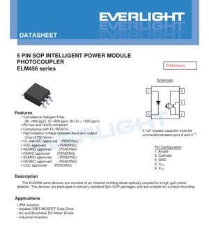
The ELM456 series represents a family of intelligent power module (IPM) photocouplers designed for high-reliability isolation in power electronics. These devices integrate an infrared emitting diode optically coupled to a high-gain photodetector within a compact, industry-standard 5-pin Small Outline Package (SOP). The primary function is to provide robust electrical isolation and signal transmission between low-voltage control circuits and high-voltage power stages, such as those found in motor drives and inverters.
The core advantage of this series lies in its high isolation capability, rated at 3750 Vrms, which is critical for safety and noise immunity in high-voltage applications. The devices are engineered for surface mounting, facilitating automated assembly processes and contributing to compact PCB designs. Compliance with halogen-free, Pb-free, RoHS, and REACH standards underscores their suitability for modern, environmentally conscious electronic manufacturing.
2. Technical Specifications and Deep Objective Interpretation
2.1 Absolute Maximum Ratings
The absolute maximum ratings define the stress limits beyond which permanent damage to the device may occur. Key parameters include a forward current (IF) of 20 mA for the input LED, an output supply voltage (VCC) of 30 V, and an output current (IO) of 15 mA. The isolation voltage (VISO) is specified as 3750 Vrms for one minute under controlled humidity (40-60% RH). The operating temperature range is from -40°C to +85°C, indicating robust performance across industrial environments. The soldering temperature rating of 260°C for 10 seconds is aligned with standard lead-free reflow profiles.
2.2 Electrical Characteristics
The electrical characteristics are divided into input, output, and transfer parameters, providing a comprehensive performance profile under typical operating conditions.
2.2.1 Input Characteristics
The forward voltage (VF) of the input LED is typically 1.45V at a forward current (IF) of 10 mA, with a maximum of 1.8V. This low VF contributes to lower power dissipation in the driving circuit. The reverse current (IR) is a maximum of 10 µA at 5V reverse bias, indicating good diode characteristics. The input capacitance (CIN) is typically 60 pF, which is a factor to consider in high-speed switching applications to avoid excessive loading on the driver.
2.2.2 Output and Transfer Characteristics
The supply current consumption is low, with ICCH (high-level supply current) typically 0.7 mA when the input is off (IF=0mA, VCC=5V). The current transfer ratio (CTR) is specified as a minimum of 220% at IF=10mA, VO=0.6V, and VCC=5V. A high CTR ensures that a relatively small input current can effectively drive the output stage, improving efficiency. The low-level output voltage (VOL) is typically 0.15V (max 0.6V) under specified conditions, ensuring a solid logic low state.
2.3 Switching Characteristics
Switching performance is critical for timing-sensitive applications like PWM gate drives. The propagation delay time to output high (TPHL) is typically 150 ns, while the delay to output low (TPLH) is typically 450 ns. The pulse width distortion (|TPHL – TPLH|) is typically 300 ns. These asymmetrical delays must be accounted for in system timing design to prevent signal distortion. The common-mode transient immunity (CMTI) is a key robustness metric, specified at a minimum of 10 kV/µs for both logic high (CMH) and logic low (CML) states. This high CMTI rating ensures reliable operation in noisy environments with fast-changing common-mode voltages, such as in motor drive systems.
3. Performance Curve Analysis
The datasheet references typical electro-optical characteristic curves. While the specific graphs are not detailed in the provided text, such curves typically illustrate the relationship between forward current and forward voltage (I-V curve), the temperature dependence of CTR, and the variation of propagation delays with load or temperature. Analyzing these curves is essential for designers to understand device behavior under non-standard conditions, optimize operating points for efficiency and speed, and ensure reliable performance across the intended temperature range. For instance, CTR generally decreases with increasing temperature, which may require derating or compensation in the design.
4. Mechanical and Package Information
4.1 Pin Configuration and Function
The device uses a 5-pin SOP configuration. The pinout is as follows: Pin 1: Anode, Pin 3: Cathode (Input LED); Pin 4: GND, Pin 5: VOUT, Pin 6: VCC (Output side). A critical design note specifies that a 0.1 µF bypass capacitor must be connected between pins 6 (VCC) and 4 (GND) to ensure stable operation and minimize noise.
4.2 Package Dimensions and Recommended Pad Layout
The datasheet includes detailed package dimension drawings (in mm) for the SOP package. It also provides a recommended pad layout for surface mounting. Adhering to this recommended footprint is crucial for achieving reliable solder joints, proper mechanical stability, and effective heat dissipation during the reflow process. The pad design considers factors like solder fillet formation and tombstoning prevention.
5. Soldering and Assembly Guidelines
The document provides specific precautions for soldering, detailing a maximum body case temperature profile compliant with IPC/JEDEC J-STD-020D for lead-free reflow. Key parameters of this profile include: a preheat stage from 150°C to 200°C over 60-120 seconds, a peak temperature (TP) of 260°C, and a time above liquidus (217°C) between 60-100 seconds. The device can withstand up to three reflow cycles. Following this profile is essential to prevent thermal damage to the plastic package and the internal semiconductor die, ensuring long-term reliability.
6. Packaging and Ordering Information
6.1 Ordering Part Number System
The part number follows the format: ELM456(Y)-VG. The "EL" prefix denotes the manufacturer. "M456" is the base device number. "Y" represents the tape and reel option (TA or TB). "V" indicates VDE approval (optional, noted as pending in this document). "G" signifies halogen-free construction. The TA and TB options differ in the feed direction from the reel, accommodating different pick-and-place machine configurations. Both options pack 1000 units per reel.
6.2 Tape and Reel Specifications
Detailed tape dimensions are provided, including pocket size (A, B), hole diameters (Do, D1), pitch (P0, P1), and tape width (W). These dimensions are critical for setting up automated assembly equipment correctly to ensure proper component feeding and placement.
6.3 Device Marking
Devices are marked on the top surface. The marking includes: "EL" (manufacturer code), "M456" (device number), a one-digit year code (Y), a two-digit week code (WW), and "V" for the VDE option. This marking allows for traceability of manufacturing date and variant.
7. Application Suggestions
7.1 Typical Application Scenarios
The ELM456 series is explicitly designed for:
- IPM (Intelligent Power Module) Isolation: Providing the necessary isolation between the microcontroller and the high-voltage IPM.
- Isolated IGBT/MOSFET Gate Drive: Driving the gates of power switches in half-bridge or full-bridge configurations while maintaining isolation.
- AC and Brushless DC Motor Drives: Isolating control signals in variable frequency drives and motor controllers.
- Industrial Inverters: Used in UPS systems, solar inverters, and other power conversion equipment.
7.2 Design Considerations and Notes
Designers must consider several key factors:
- Bypass Capacitor: The mandatory 0.1 µF capacitor between VCC and GND (pins 6 & 4) must be placed as close as possible to the device pins to be effective.
- Propagation Delays: The asymmetric propagation delays (TPHL vs TPLH) will affect the transmitted pulse width. Compensation may be needed in software or via external circuitry if precise pulse integrity is required.
- Current Limiting Resistor: An external resistor is always required in series with the input LED (Anode, Pin 1) to limit the forward current (IF) to a safe value, typically between 5-16 mA as per application needs, and never exceeding 20 mA.
- Load Resistor: The output typically requires a pull-up or load resistor (RL) connected between VOUT (Pin 5) and VCC. The value of RL influences switching speed and current consumption; 350 Ω is used in the datasheet test conditions.
- Isolation Creepage and Clearance: PCB layout must maintain adequate creepage and clearance distances (as per relevant safety standards like IEC 60950-1 or IEC 61800-5-1) between the primary (input) and secondary (output) sides of the circuit, even though the device itself provides the isolation barrier.
8. Technical Comparison and Differentiation
While a direct comparison with specific competitor parts is not provided in the source document, the ELM456 series can be evaluated based on its published specifications. Key differentiators likely include its high 3750 Vrms isolation rating, which may be superior to many standard photocouplers rated at 2500 Vrms or 5000 Vrms. The combination of high CMTI (10 kV/µs min) and a compact SOP package is advantageous for space-constrained, high-noise applications. The halogen-free and comprehensive environmental compliance (RoHS, REACH) is a significant advantage for markets with strict regulatory requirements. The pending approvals from major safety agencies (UL, cUL, VDE, etc.) indicate design intent for globally recognized safety standards.
9. Frequently Asked Questions (Based on Technical Parameters)
Q1: What is the purpose of the high isolation voltage (3750 Vrms)?
A1: This rating ensures safe operation and prevents hazardous breakdown between the low-voltage control circuit and the high-voltage power circuit. It is a safety requirement for many mains-connected equipment (e.g., 230VAC/400VAC drives) and provides robust noise immunity.
Q2: Why are the propagation delay times (TPHL and TPLH) different?
A2: The asymmetry is inherent to the internal photodetector and amplifier design. The turn-off process (TPLH) is typically slower than turn-on (TPHL). This must be considered in timing-critical applications to avoid pulse distortion.
Q3: How do I select the value for the input current limiting resistor?
A3: Use Ohm's law: RLIMIT = (VDRIVE - VF) / IF. VDRIVE is your logic supply voltage (e.g., 3.3V, 5V). Use the typical VF (1.45V) for calculation, but ensure IF does not exceed 20 mA under worst-case conditions (min VDRIVE, min RLIMIT tolerance). A typical IF for guaranteed CTR is 10 mA.
Q4: What does "Common Mode Transient Immunity" mean, and why is it important?
A4: CMTI measures the device's ability to reject fast voltage transients that appear equally on both sides of the isolation barrier (e.g., due to switching noise in a motor drive). A low CMTI can cause the output to glitch falsely. A rating of 10 kV/µs is considered good for industrial motor control applications.
Q5: The datasheet lists many safety approvals as "PENDING." Can I use this part in a final product?
A5: For a product requiring certified safety approval (UL, VDE, etc.), you must verify the final status of these certifications with the manufacturer or distributor before finalizing the design and proceeding to production. Using a device without the required certification may prevent your end product from achieving its own safety certification.
10. Practical Design and Usage Case
Case: Isolated Gate Driver for a 3-Phase BLDC Motor Inverter
In a typical 3-phase inverter driving a Brushless DC motor, six power switches (IGBTs or MOSFETs) are used. Each switch requires an isolated gate drive signal. The ELM456 can be used for each of these six channels. The microcontroller's PWM signals are fed into the anode (via current-limiting resistors) of six ELM456 devices. The output (VOUT) of each photocoupler drives the input of a dedicated gate driver IC, which then provides the high-current pulses needed to switch the IGBTs rapidly. The 3750 Vrms isolation of the ELM456 protects the sensitive microcontroller from the high-voltage DC bus (often 300-600VDC). The high CMTI ensures that the noisy switching transients from the inverter do not cause false triggering of the gate signals. The compact SOP package allows all six isolators to fit neatly near the microcontroller. The design must include six 0.1 µF bypass capacitors placed directly at the VCC/GND pins of each ELM456.
11. Operating Principle Introduction
A photocoupler (or optocoupler) is a device that transfers electrical signals between two isolated circuits using light. The ELM456 consists of two main parts on separate die within a single, opaque package. On the input side, an infrared Light Emitting Diode (LED) converts the incoming electrical signal into a proportional intensity of infrared light. This light travels across a transparent isolation barrier (often a mold compound or air gap). On the output side, a photodetector (typically a phototransistor or a photo-diode plus amplifier) receives this light and converts it back into an electrical signal. The key is that there is no electrical connection—only an optical one—across the barrier, which provides the galvanic isolation. The high gain amplifier in the ELM456's output stage allows it to achieve a high Current Transfer Ratio (CTR), meaning a small input current produces a much larger usable output current.
12. Technology Trends
The field of galvanic isolation is evolving. While traditional photocouplers like the ELM456 remain highly popular due to their maturity, cost-effectiveness, and high voltage ratings, alternative technologies are gaining traction. Capacitive isolators use changing electric fields across a silicon dioxide barrier, offering higher speed, lower power consumption, and higher integration (multiple channels in one package). Magnetic (inductive) isolators use transformer coils, also offering high speed and robustness. However, photocouplers continue to hold significant advantages in very high isolation voltage capabilities, simplicity, and proven long-term reliability in harsh environments. Trends within photocoupler technology itself include the push for higher speeds (lower propagation delays), higher CMTI for noisier applications, lower power consumption, smaller package footprints, and integration of more features like fail-safe outputs or I2C isolation. The move towards halogen-free and enhanced material compliance, as seen in the ELM456, is a universal industry trend driven by environmental regulations.
LED Specification Terminology
Complete explanation of LED technical terms
Photoelectric Performance
| Term | Unit/Representation | Simple Explanation | Why Important |
|---|---|---|---|
| Luminous Efficacy | lm/W (lumens per watt) | Light output per watt of electricity, higher means more energy efficient. | Directly determines energy efficiency grade and electricity cost. |
| Luminous Flux | lm (lumens) | Total light emitted by source, commonly called "brightness". | Determines if the light is bright enough. |
| Viewing Angle | ° (degrees), e.g., 120° | Angle where light intensity drops to half, determines beam width. | Affects illumination range and uniformity. |
| CCT (Color Temperature) | K (Kelvin), e.g., 2700K/6500K | Warmth/coolness of light, lower values yellowish/warm, higher whitish/cool. | Determines lighting atmosphere and suitable scenarios. |
| CRI / Ra | Unitless, 0–100 | Ability to render object colors accurately, Ra≥80 is good. | Affects color authenticity, used in high-demand places like malls, museums. |
| SDCM | MacAdam ellipse steps, e.g., "5-step" | Color consistency metric, smaller steps mean more consistent color. | Ensures uniform color across same batch of LEDs. |
| Dominant Wavelength | nm (nanometers), e.g., 620nm (red) | Wavelength corresponding to color of colored LEDs. | Determines hue of red, yellow, green monochrome LEDs. |
| Spectral Distribution | Wavelength vs intensity curve | Shows intensity distribution across wavelengths. | Affects color rendering and quality. |
Electrical Parameters
| Term | Symbol | Simple Explanation | Design Considerations |
|---|---|---|---|
| Forward Voltage | Vf | Minimum voltage to turn on LED, like "starting threshold". | Driver voltage must be ≥Vf, voltages add up for series LEDs. |
| Forward Current | If | Current value for normal LED operation. | Usually constant current drive, current determines brightness & lifespan. |
| Max Pulse Current | Ifp | Peak current tolerable for short periods, used for dimming or flashing. | Pulse width & duty cycle must be strictly controlled to avoid damage. |
| Reverse Voltage | Vr | Max reverse voltage LED can withstand, beyond may cause breakdown. | Circuit must prevent reverse connection or voltage spikes. |
| Thermal Resistance | Rth (°C/W) | Resistance to heat transfer from chip to solder, lower is better. | High thermal resistance requires stronger heat dissipation. |
| ESD Immunity | V (HBM), e.g., 1000V | Ability to withstand electrostatic discharge, higher means less vulnerable. | Anti-static measures needed in production, especially for sensitive LEDs. |
Thermal Management & Reliability
| Term | Key Metric | Simple Explanation | Impact |
|---|---|---|---|
| Junction Temperature | Tj (°C) | Actual operating temperature inside LED chip. | Every 10°C reduction may double lifespan; too high causes light decay, color shift. |
| Lumen Depreciation | L70 / L80 (hours) | Time for brightness to drop to 70% or 80% of initial. | Directly defines LED "service life". |
| Lumen Maintenance | % (e.g., 70%) | Percentage of brightness retained after time. | Indicates brightness retention over long-term use. |
| Color Shift | Δu′v′ or MacAdam ellipse | Degree of color change during use. | Affects color consistency in lighting scenes. |
| Thermal Aging | Material degradation | Deterioration due to long-term high temperature. | May cause brightness drop, color change, or open-circuit failure. |
Packaging & Materials
| Term | Common Types | Simple Explanation | Features & Applications |
|---|---|---|---|
| Package Type | EMC, PPA, Ceramic | Housing material protecting chip, providing optical/thermal interface. | EMC: good heat resistance, low cost; Ceramic: better heat dissipation, longer life. |
| Chip Structure | Front, Flip Chip | Chip electrode arrangement. | Flip chip: better heat dissipation, higher efficacy, for high-power. |
| Phosphor Coating | YAG, Silicate, Nitride | Covers blue chip, converts some to yellow/red, mixes to white. | Different phosphors affect efficacy, CCT, and CRI. |
| Lens/Optics | Flat, Microlens, TIR | Optical structure on surface controlling light distribution. | Determines viewing angle and light distribution curve. |
Quality Control & Binning
| Term | Binning Content | Simple Explanation | Purpose |
|---|---|---|---|
| Luminous Flux Bin | Code e.g., 2G, 2H | Grouped by brightness, each group has min/max lumen values. | Ensures uniform brightness in same batch. |
| Voltage Bin | Code e.g., 6W, 6X | Grouped by forward voltage range. | Facilitates driver matching, improves system efficiency. |
| Color Bin | 5-step MacAdam ellipse | Grouped by color coordinates, ensuring tight range. | Guarantees color consistency, avoids uneven color within fixture. |
| CCT Bin | 2700K, 3000K etc. | Grouped by CCT, each has corresponding coordinate range. | Meets different scene CCT requirements. |
Testing & Certification
| Term | Standard/Test | Simple Explanation | Significance |
|---|---|---|---|
| LM-80 | Lumen maintenance test | Long-term lighting at constant temperature, recording brightness decay. | Used to estimate LED life (with TM-21). |
| TM-21 | Life estimation standard | Estimates life under actual conditions based on LM-80 data. | Provides scientific life prediction. |
| IESNA | Illuminating Engineering Society | Covers optical, electrical, thermal test methods. | Industry-recognized test basis. |
| RoHS / REACH | Environmental certification | Ensures no harmful substances (lead, mercury). | Market access requirement internationally. |
| ENERGY STAR / DLC | Energy efficiency certification | Energy efficiency and performance certification for lighting. | Used in government procurement, subsidy programs, enhances competitiveness. |