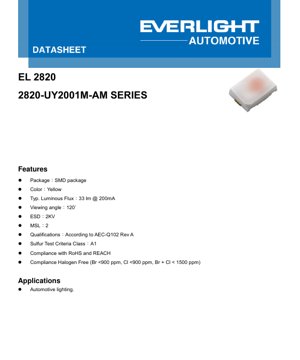
1. Product Overview
The 2820-UY2001M-AM series represents a high-reliability, surface-mount LED component engineered specifically for demanding automotive lighting applications. This device is characterized by its compact 2820 SMD package footprint, delivering a typical luminous flux of 33 lumens at a standard operating current of 200mA. The primary light output is in the yellow spectrum, with a dominant wavelength centered around 589nm. A key differentiator for this product is its compliance with the stringent AEC-Q102 Rev A qualification standard for discrete optoelectronic semiconductors in automotive applications, ensuring performance and longevity under the harsh environmental conditions typical of the automotive industry. Additional certifications include adherence to RoHS, REACH, and halogen-free manufacturing criteria, making it a suitable choice for modern, eco-conscious designs.
1.1 Core Advantages and Target Market
The core advantages of this LED series are rooted in its automotive-grade robustness and optimized photometric performance. The device features a high electrostatic discharge (ESD) tolerance of 2KV (HBM), enhancing its handling and assembly reliability. Its wide 120-degree viewing angle provides excellent spatial light distribution, which is crucial for applications like interior ambient lighting, dashboard illumination, and exterior signal lighting where uniform brightness is required. The primary target market is the automotive sector, including Tier-1 suppliers and OEMs developing lighting modules for passenger vehicles, commercial trucks, and motorcycles. Its reliability specifications also make it a candidate for other high-reliability markets such as industrial indicator lights and outdoor signage where long-term performance is critical.
2. In-Depth Technical Parameter Analysis
A thorough understanding of the electrical, optical, and thermal parameters is essential for proper circuit design and system integration.
2.1 Photometric and Optical Characteristics
The central photometric parameter is the luminous flux (Φv), specified with a typical value of 33 lumens at IF = 200mA. The minimum and maximum values are 27 lm and 45 lm respectively, with a measurement tolerance of ±8%. The dominant wavelength (λd) is 589nm typical, with a range from 585nm to 594nm and a tight tolerance of ±1nm. This places the emission firmly in the yellow color region. The spatial light distribution is defined by a wide viewing angle of 120 degrees, measured at the half-intensity points (where luminous intensity is 50% of the peak value). This parameter has a tolerance of ±5°.
2.2 Electrical Characteristics
The forward voltage (VF) is a critical parameter for power supply design and thermal management. At the typical operating current of 200mA, VF is 2.4V, with a range from 2.00V to 2.75V (tolerance ±0.05V). The recommended continuous forward current (IF) is 200mA, with an absolute maximum rating of 250mA. For surge conditions, the device can withstand a peak current (IFM) of 1000mA for pulses ≤10μs with a very low duty cycle (D=0.005). It is important to note that this LED is not designed for reverse bias operation.
2.3 Thermal Characteristics
Effective heat dissipation is paramount for LED performance and lifetime. The thermal resistance from the semiconductor junction to the solder point (RthJS) is provided in two values: 32 K/W (typical, real measurement) and 28 K/W (typical, electrical measurement). The maximum permissible junction temperature (TJ) is 150°C. The device is rated for an operating temperature range (Topr) of -40°C to +125°C, which is standard for automotive components. The power dissipation (Pd) is rated at 687.5 mW maximum.
3. Binning System Explanation
To ensure color and brightness consistency in production, LEDs are sorted into bins. The 2820-UY2001M-AM series uses a three-dimensional binning system.
3.1 Luminous Flux Binning
Luminous flux is categorized into three bins: F1 (27-33 lm), F2 (33-39 lm), and F3 (39-45 lm). The part number suffix \"M\" indicates a Medium brightness level, which typically corresponds to the F1 or lower end of the F2 bin.
3.2 Forward Voltage Binning
Forward voltage is binned to aid in current matching for multi-LED arrays. The bins are: 2022 (2.00-2.25V), 2225 (2.25-2.50V), and 2527 (2.50-2.75V).
3.3 Dominant Wavelength Binning
Dominant wavelength bins ensure color uniformity: 8588 (585-588nm), 8891 (588-591nm), and 9194 (591-594nm). The \"UY\" color code signifies the yellow group, which encompasses these bins.
4. Performance Curve Analysis
The datasheet provides several graphs essential for predicting performance under non-standard conditions.
4.1 IV Curve and Relative Luminous Flux
The Forward Current vs. Forward Voltage graph shows a typical exponential diode relationship. At 200mA, the voltage is clustered around 2.4V. The Relative Luminous Flux vs. Forward Current graph is sub-linear; flux increases with current but begins to saturate at higher currents due to thermal effects and efficiency droop.
4.2 Temperature Dependence
The Relative Forward Voltage vs. Junction Temperature graph shows a negative temperature coefficient; VF decreases linearly as temperature increases (approximately -2 mV/°C). This can be used for junction temperature estimation. The Relative Luminous Flux vs. Junction Temperature graph shows a significant decrease in light output as temperature rises. At 125°C, the flux is only about 60-70% of its value at 25°C, highlighting the critical need for effective thermal management. The Relative Wavelength vs. Junction Temperature graph indicates a slight redshift (increase in wavelength) with increasing temperature.
4.3 Spectral Distribution and Derating
The Relative Spectral Distribution graph confirms a monochromatic yellow emission peak around 589nm with minimal unwanted spectral components. The Forward Current Derating Curve dictates the maximum allowable continuous current based on the solder pad temperature (TS). At the maximum TS of 125°C, the current must be derated to 250mA (the absolute max). For reliable operation, it is advised to operate significantly below this limit.
4.4 Pulse Handling Capability
The Permissible Pulse Handling graph defines the peak pulse current (IFP) allowed for a given pulse width (tp) and duty cycle (D). For very short pulses (e.g., 10μs), the current can far exceed the DC maximum. This is relevant for PWM dimming applications.
5. Mechanical and Package Information
5.1 Physical Dimensions
The LED is housed in a 2820 SMD package. The nominal dimensions are 2.8mm in length and 2.0mm in width. The exact height and detailed dimensional drawing, including lens shape and lead frame placement, are provided in the mechanical drawing, with standard tolerances of ±0.1mm unless otherwise specified.
5.2 Recommended Solder Pad Layout
A land pattern design is recommended to ensure reliable soldering and optimal thermal performance. The layout includes pads for the two electrical anodes/cathodes and a central thermal pad for heat sinking. Adhering to this footprint is crucial for mechanical stability and heat transfer from the LED's thermal pad to the PCB.
5.3 Polarity Identification
The polarity (anode and cathode) is marked on the device, typically with a visual indicator like a notch, a dot, or a chamfered corner. The datasheet's mechanical drawing specifies this marking. Correct polarity must be observed during assembly to prevent damage.
6. Soldering and Assembly Guidelines
6.1 Reflow Soldering Profile
The component is compatible with standard infrared or convection reflow soldering processes. The maximum peak solder temperature should not exceed 260°C, and the time above 260°C should be limited to 30 seconds maximum. A standard ramp-up, preheat, reflow, and cooling profile for lead-free (SnAgCu) solder is applicable. The Moisture Sensitivity Level (MSL) is rated at Level 2, meaning the device can be exposed to factory floor conditions for up to one year prior to soldering without requiring baking.
6.2 Precautions for Use
Key precautions include: Avoid applying reverse voltage. Use current-limiting circuitry; do not drive directly from a voltage source. Implement proper ESD handling procedures during assembly. Ensure the thermal pad is properly soldered to the PCB's copper pour for effective heat dissipation. Do not exceed the absolute maximum ratings for current, voltage, or temperature.
6.3 Storage Conditions
The storage temperature range (Tstg) is -40°C to +125°C. For long-term storage exceeding the MSL-2 floor life, the devices should be stored in a dry environment or in moisture-barrier bags with desiccant.
7. Packaging and Ordering Information
7.1 Packaging Specification
The LEDs are supplied on tape and reel for automated pick-and-place assembly. The packaging information details the reel dimensions, tape width, pocket spacing, and orientation of components on the tape.
7.2 Part Numbering System
The part number 2820-UY2001M-AM is decoded as follows:
- 2820: Product family and package size (2.8mm x 2.0mm).
- UY: Color (Yellow).
- 200: Test current in milliamps (200mA).
- 1: Lead frame type (1 = Gold-plated).
- M: Brightness level (M = Medium).
- AM: Designates Automotive application grade.
8. Application Recommendations
8.1 Typical Application Scenarios
The primary application is automotive lighting. Specific uses include:
- Interior Lighting: Dashboard backlighting, switch illumination, footwell lights, ambient lighting.
- Exterior Signaling: Center High-Mount Stop Lights (CHMSL), side marker lights, turn signal indicators (often in combination with other colors or lenses).
- Display Backlighting: Instrument cluster icons, infotainment system buttons.
8.2 Design Considerations
Thermal Management: This is the most critical aspect. Use a PCB with adequate thermal vias under the thermal pad connected to internal ground planes or dedicated heat sinks. Calculate the expected junction temperature using RthJS and the power dissipation (Pd = VF * IF). Keep TJ well below 150°C for long life.
Drive Circuitry: Use a constant current driver, not a constant voltage source, to ensure stable light output and prevent thermal runaway. The driver should be rated for the automotive voltage range (typically 9-16V with load dump transients). Consider PWM dimming for brightness control, referencing the pulse handling capabilities.
Optical Design: The 120° viewing angle may require secondary optics (lenses, light guides) to shape the beam for specific applications like indicator lights.
9. Technical Comparison and Differentiation
Compared to standard commercial-grade yellow LEDs, the 2820-UY2001M-AM series offers distinct advantages:
- AEC-Q102 Compliance: This is the key differentiator, involving rigorous testing for temperature cycling, humidity, high-temperature operating life (HTOL), and other stressors not required for consumer parts.
- Extended Temperature Range: Operation from -40°C to +125°C is essential for automotive engine bay or exterior applications.
- Sulfur Resistance: The datasheet specifies Sulfur Test Criteria Class A1, indicating resistance to corrosive atmospheres found in some automotive and industrial environments.
- Controlled Binning: Tighter binning on flux, voltage, and wavelength ensures better consistency in automotive lighting modules, where color and brightness matching are critical.
10. Frequently Asked Questions (FAQs)
Q1: What is the typical forward voltage at 200mA?
A1: The typical forward voltage (VF) is 2.4 volts, with a range from 2.00V to 2.75V depending on the voltage bin.
Q2: Can I drive this LED with a 3.3V supply?
A2: Not directly. Since VF is ~2.4V, a series current-limiting resistor or, preferably, a constant-current driver is required to set the current to 200mA from a 3.3V rail. A simple resistor calculation is R = (Vsupply - VF) / IF.
Q3: How much does light output drop at high temperature?
A3: Referencing the performance graph, relative luminous flux drops to approximately 60-70% of its 25°C value when the junction temperature reaches 125°C. This underscores the need for excellent thermal design.
Q4: Is this LED suitable for PWM dimming?
A4: Yes, it is suitable. The Permissible Pulse Handling graph should be consulted to ensure the peak current and pulse width used in the PWM scheme do not exceed the safe operating area. Typical PWM frequencies are in the hundreds of Hz to several kHz.
Q5: What does the \"AM\" suffix mean?
A5: The \"AM\" suffix explicitly denotes that this component is qualified and intended for Automotive applications, meeting the relevant industry standards (AEC-Q102).
11. Practical Design Case Study
Scenario: Designing a multi-LED array for an automotive interior ambient light strip requiring uniform yellow illumination.
Design Steps:
1. Electrical Design: Determine array configuration (series/parallel). For uniform current, a series string is best. If 12V is available, up to 4 LEDs (4 * 2.4V = 9.6V) could be placed in series with a current-limiting resistor or a linear constant-current driver. For more LEDs, a switching constant-current driver is recommended.
2. Thermal Design: Calculate total power: 4 LEDs * (2.4V * 0.2A) = 1.92W. Design the PCB with a large copper area on the layer where the LED thermal pads attach, using multiple thermal vias to spread heat to other layers.
3. Optical/Mechanical: Place LEDs at a pitch that, combined with their 120° beam, creates a seamless line of light. A diffuser cover will help blend the individual LED spots.
4. Component Selection: Specify the exact bin codes (e.g., F1 for flux, 8891 for wavelength) in the purchase order to ensure color and brightness consistency across the production run.
12. Operating Principle
This LED is a semiconductor photonic device. When a forward voltage exceeding its bandgap energy is applied across the anode and cathode, electrons and holes recombine in the active region of the semiconductor chip (typically based on materials like InGaN or AlInGaP for yellow light). This recombination process releases energy in the form of photons (light). The specific wavelength (color) of the emitted light is determined by the bandgap energy of the semiconductor material. The light is then extracted through the epoxy or silicone lens of the package, which also provides environmental protection and determines the viewing angle.
13. Technology Trends
The trend in automotive LEDs like this series is towards:
Higher Efficiency (lm/W): Ongoing material and package improvements aim to deliver more lumens per watt, reducing electrical load and thermal challenges.
Increased Power Density: Smaller packages delivering higher flux, enabling more compact and stylized lighting designs.
Enhanced Reliability and Testing: Stricter AEC qualifications and the introduction of new tests for emerging failure modes (e.g., more aggressive sulfur resistance).
Integrated Solutions: The growth of LED modules with integrated drivers, controllers, and communication interfaces (LIN, CAN) rather than discrete components. While this part is a discrete emitter, it fits into the broader ecosystem of these advanced modules.
LED Specification Terminology
Complete explanation of LED technical terms
Photoelectric Performance
| Term | Unit/Representation | Simple Explanation | Why Important |
|---|---|---|---|
| Luminous Efficacy | lm/W (lumens per watt) | Light output per watt of electricity, higher means more energy efficient. | Directly determines energy efficiency grade and electricity cost. |
| Luminous Flux | lm (lumens) | Total light emitted by source, commonly called "brightness". | Determines if the light is bright enough. |
| Viewing Angle | ° (degrees), e.g., 120° | Angle where light intensity drops to half, determines beam width. | Affects illumination range and uniformity. |
| CCT (Color Temperature) | K (Kelvin), e.g., 2700K/6500K | Warmth/coolness of light, lower values yellowish/warm, higher whitish/cool. | Determines lighting atmosphere and suitable scenarios. |
| CRI / Ra | Unitless, 0–100 | Ability to render object colors accurately, Ra≥80 is good. | Affects color authenticity, used in high-demand places like malls, museums. |
| SDCM | MacAdam ellipse steps, e.g., "5-step" | Color consistency metric, smaller steps mean more consistent color. | Ensures uniform color across same batch of LEDs. |
| Dominant Wavelength | nm (nanometers), e.g., 620nm (red) | Wavelength corresponding to color of colored LEDs. | Determines hue of red, yellow, green monochrome LEDs. |
| Spectral Distribution | Wavelength vs intensity curve | Shows intensity distribution across wavelengths. | Affects color rendering and quality. |
Electrical Parameters
| Term | Symbol | Simple Explanation | Design Considerations |
|---|---|---|---|
| Forward Voltage | Vf | Minimum voltage to turn on LED, like "starting threshold". | Driver voltage must be ≥Vf, voltages add up for series LEDs. |
| Forward Current | If | Current value for normal LED operation. | Usually constant current drive, current determines brightness & lifespan. |
| Max Pulse Current | Ifp | Peak current tolerable for short periods, used for dimming or flashing. | Pulse width & duty cycle must be strictly controlled to avoid damage. |
| Reverse Voltage | Vr | Max reverse voltage LED can withstand, beyond may cause breakdown. | Circuit must prevent reverse connection or voltage spikes. |
| Thermal Resistance | Rth (°C/W) | Resistance to heat transfer from chip to solder, lower is better. | High thermal resistance requires stronger heat dissipation. |
| ESD Immunity | V (HBM), e.g., 1000V | Ability to withstand electrostatic discharge, higher means less vulnerable. | Anti-static measures needed in production, especially for sensitive LEDs. |
Thermal Management & Reliability
| Term | Key Metric | Simple Explanation | Impact |
|---|---|---|---|
| Junction Temperature | Tj (°C) | Actual operating temperature inside LED chip. | Every 10°C reduction may double lifespan; too high causes light decay, color shift. |
| Lumen Depreciation | L70 / L80 (hours) | Time for brightness to drop to 70% or 80% of initial. | Directly defines LED "service life". |
| Lumen Maintenance | % (e.g., 70%) | Percentage of brightness retained after time. | Indicates brightness retention over long-term use. |
| Color Shift | Δu′v′ or MacAdam ellipse | Degree of color change during use. | Affects color consistency in lighting scenes. |
| Thermal Aging | Material degradation | Deterioration due to long-term high temperature. | May cause brightness drop, color change, or open-circuit failure. |
Packaging & Materials
| Term | Common Types | Simple Explanation | Features & Applications |
|---|---|---|---|
| Package Type | EMC, PPA, Ceramic | Housing material protecting chip, providing optical/thermal interface. | EMC: good heat resistance, low cost; Ceramic: better heat dissipation, longer life. |
| Chip Structure | Front, Flip Chip | Chip electrode arrangement. | Flip chip: better heat dissipation, higher efficacy, for high-power. |
| Phosphor Coating | YAG, Silicate, Nitride | Covers blue chip, converts some to yellow/red, mixes to white. | Different phosphors affect efficacy, CCT, and CRI. |
| Lens/Optics | Flat, Microlens, TIR | Optical structure on surface controlling light distribution. | Determines viewing angle and light distribution curve. |
Quality Control & Binning
| Term | Binning Content | Simple Explanation | Purpose |
|---|---|---|---|
| Luminous Flux Bin | Code e.g., 2G, 2H | Grouped by brightness, each group has min/max lumen values. | Ensures uniform brightness in same batch. |
| Voltage Bin | Code e.g., 6W, 6X | Grouped by forward voltage range. | Facilitates driver matching, improves system efficiency. |
| Color Bin | 5-step MacAdam ellipse | Grouped by color coordinates, ensuring tight range. | Guarantees color consistency, avoids uneven color within fixture. |
| CCT Bin | 2700K, 3000K etc. | Grouped by CCT, each has corresponding coordinate range. | Meets different scene CCT requirements. |
Testing & Certification
| Term | Standard/Test | Simple Explanation | Significance |
|---|---|---|---|
| LM-80 | Lumen maintenance test | Long-term lighting at constant temperature, recording brightness decay. | Used to estimate LED life (with TM-21). |
| TM-21 | Life estimation standard | Estimates life under actual conditions based on LM-80 data. | Provides scientific life prediction. |
| IESNA | Illuminating Engineering Society | Covers optical, electrical, thermal test methods. | Industry-recognized test basis. |
| RoHS / REACH | Environmental certification | Ensures no harmful substances (lead, mercury). | Market access requirement internationally. |
| ENERGY STAR / DLC | Energy efficiency certification | Energy efficiency and performance certification for lighting. | Used in government procurement, subsidy programs, enhances competitiveness. |