Table of Contents
- 1. Product Overview
- 1.1 Core Advantages and Target Market
- 2. Technical Parameter Deep-Dive
- 2.1 Absolute Maximum Ratings
- 2.2 Electro-Optical Characteristics
- 3. Binning System Explanation
- 4. Performance Curve Analysis
- 4.1 Relative Intensity vs. Wavelength
- 4.2 Directivity Pattern
- 4.3 Forward Current vs. Forward Voltage (I-V Curve)
- 4.4 Relative Intensity vs. Forward Current
- 4.5 Temperature Dependence Curves
- 5. Mechanical and Package Information
- 6. Soldering and Assembly Guidelines
- 6.1 Lead Forming
- 6.2 Storage
- 6.3 Soldering Process
- 6.4 Cleaning
- 6.5 Heat Management
- 6.6 ESD (Electrostatic Discharge) Precautions
- 7. Packaging and Ordering Information
- 7.1 Packing Specification
- 7.2 Label Explanation
- 8. Application Suggestions
- 8.1 Typical Application Scenarios
- 8.2 Design Considerations
- 9. Technical Comparison and Differentiation
- 10. Frequently Asked Questions (Based on Technical Parameters)
- 11. Practical Design and Usage Case
- 12. Operating Principle Introduction
- 13. Technology Trends
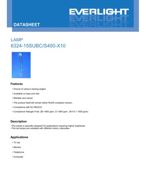
1. Product Overview
This document provides the complete technical specifications for a high-brightness blue LED lamp, identified by the part number 6324-15SUBC/S400-X10. This component belongs to a series specifically engineered for applications demanding superior luminous output. The LED is offered in a standard lamp package configuration, making it suitable for a wide range of electronic assembly processes. Its core design prioritizes reliability and robustness in various operating environments.
The device is compliant with major environmental and safety directives, including RoHS (Restriction of Hazardous Substances), EU REACH regulations, and is manufactured as a halogen-free component. This compliance ensures the product meets stringent international standards for electronic components. The LED is available supplied on tape and reel for automated pick-and-place assembly, enhancing production efficiency in high-volume manufacturing settings.
1.1 Core Advantages and Target Market
The primary advantage of this LED is its combination of high luminous intensity and a reliable package. With a typical intensity of 500 millicandelas (mcd) at a standard 20mA drive current, it delivers significant brightness for its form factor. The product is designed for general-purpose indicator and backlighting applications in consumer and industrial electronics. Key target markets include the manufacturers of television sets, computer monitors, telephones, and various computer peripherals where consistent, bright blue indication or illumination is required. The choice of various viewing angles allows designers to select the optimal radiation pattern for their specific application, balancing between wide area coverage and axial intensity.
2. Technical Parameter Deep-Dive
This section provides a detailed, objective analysis of the LED's key technical parameters as defined in its datasheet. Understanding these specifications is crucial for proper circuit design and ensuring long-term reliability.
2.1 Absolute Maximum Ratings
The Absolute Maximum Ratings define the stress limits beyond which permanent damage to the device may occur. These are not operating conditions.
- Continuous Forward Current (IF): 25 mA. This is the maximum DC current that can be continuously applied to the LED.
- Peak Forward Current (IFP): 100 mA. This pulsed current rating (at a duty cycle of 1/10 and 1 kHz frequency) allows for brief periods of overdrive, useful for multiplexing or strobe applications.
- Reverse Voltage (VR): 5 V. Exceeding this voltage in reverse bias can cause junction breakdown.
- Power Dissipation (Pd): 90 mW. This is the maximum power the package can dissipate as heat, calculated as Forward Voltage multiplied by Forward Current.
- Operating & Storage Temperature: The device can operate from -40°C to +85°C and be stored from -40°C to +100°C.
- Soldering Temperature: The leads can withstand 260°C for 5 seconds, which is compatible with standard lead-free reflow soldering profiles.
2.2 Electro-Optical Characteristics
These parameters are measured at a standard test condition of 25°C ambient temperature and a forward current (IF) of 20 mA, unless otherwise specified.
- Luminous Intensity (Iv): Typical value is 500 mcd, with a minimum of 250 mcd. This specifies the perceived brightness of the LED as measured by the human eye.
- Viewing Angle (2θ1/2): 60 degrees (typical). This is the full angle at which the luminous intensity drops to half of its peak axial value.
- Peak Wavelength (λp): 468 nm (typical). This is the wavelength at which the spectral power distribution of the emitted light is maximum.
- Dominant Wavelength (λd): 470 nm (typical). This is the single wavelength perceived by the human eye, defining the "blue" color of the LED.
- Spectrum Radiation Bandwidth (Δλ): 35 nm (typical). This indicates the spectral width of the emitted light, measured at half the maximum intensity (FWHM).
- Forward Voltage (VF): Ranges from 2.7V (min) to 3.7V (max), with a typical value of 3.3V at 20mA. This is crucial for designing the current-limiting circuitry.
- Reverse Current (IR): Maximum of 50 μA when a 5V reverse bias is applied.
The datasheet also notes measurement uncertainties: ±0.1V for VF, ±10% for Iv, and ±1.0nm for λd.
3. Binning System Explanation
The product utilizes a binning system to categorize units based on key optical and electrical parameters. This ensures consistency within a production batch for applications requiring tight color or brightness matching. The packing label includes codes for these bins:
- CAT: Ranks of Luminous Intensity. Units are sorted into bins based on their measured light output.
- HUE: Ranks of Dominant Wavelength. This bins LEDs according to their specific shade of blue.
- REF: Ranks of Forward Voltage. LEDs are grouped by their forward voltage drop at the test current.
Designers should consult with the supplier for the specific bin code definitions and availability to ensure the selected bin meets the application's requirements for color consistency and electrical performance.
4. Performance Curve Analysis
The datasheet provides several characteristic curves that illustrate the device's behavior under varying conditions. These are essential for understanding performance beyond the single-point specifications at 25°C/20mA.
4.1 Relative Intensity vs. Wavelength
This curve graphically shows the spectral power distribution, with a peak around 468 nm and a typical FWHM of 35 nm, confirming the monochromatic blue emission from the InGaN chip.
4.2 Directivity Pattern
A polar plot illustrates the spatial distribution of light, corresponding to the 60-degree viewing angle. The intensity is highest along the central axis (0°) and decreases symmetrically towards the edges.
4.3 Forward Current vs. Forward Voltage (I-V Curve)
This curve shows the exponential relationship typical of a diode. The forward voltage increases logarithmically with current. At the recommended 20mA operating point, the voltage is typically 3.3V. This curve is vital for thermal management, as VF has a negative temperature coefficient.
4.4 Relative Intensity vs. Forward Current
This plot demonstrates that light output is approximately linear with current in the normal operating range. Driving the LED beyond its maximum ratings will not yield proportional increases in light and will generate excessive heat.
4.5 Temperature Dependence Curves
Two key curves show the effect of ambient temperature (Ta):
- Relative Intensity vs. Ambient Temp.: Luminous output decreases as ambient temperature rises. This de-rating must be accounted for in designs operating at high temperatures.
- Forward Current vs. Ambient Temp.: For a fixed voltage, the forward current would increase with temperature due to the negative temperature coefficient of VF. This highlights the critical importance of using a constant-current driver, not a constant-voltage source, to prevent thermal runaway.
5. Mechanical and Package Information
The LED is housed in a standard lamp-style package. The package drawing provides critical dimensions for PCB footprint design and clearance checks.
- All dimensions are provided in millimeters.
- A key note specifies that the height of the flange must be less than 1.5mm (0.059 inches).
- The default tolerance for unspecified dimensions is ±0.25mm.
- The drawing typically shows lead spacing, package body size, lens shape, and the position of the cathode indicator (usually a flat side or shorter lead).
Designers must adhere strictly to these dimensions when creating the PCB land pattern to ensure proper soldering and alignment.
6. Soldering and Assembly Guidelines
Proper handling is essential to maintain reliability. The datasheet provides detailed instructions.
6.1 Lead Forming
- Bending must occur at least 3mm from the epoxy bulb base.
- Form leads before soldering.
- Avoid stressing the package; cut leads at room temperature.
- PCB holes must align perfectly with LED leads to avoid mounting stress.
6.2 Storage
- Store at ≤30°C and ≤70% RH. Shelf life is 3 months from shipment.
- For longer storage (up to 1 year), use a sealed container with nitrogen and desiccant.
- Avoid rapid temperature changes in humid environments to prevent condensation.
6.3 Soldering Process
Hand Soldering: Iron tip ≤300°C (max 30W), time ≤3 seconds, keep solder joint ≥3mm from bulb. Wave/DIP Soldering: Preheat ≤100°C (≤60 sec), solder bath ≤260°C for ≤5 sec, keep joint ≥3mm from bulb. A recommended soldering profile graph is provided, showing a gradual ramp-up, a plateau within the 260°C limit, and a controlled cooling ramp. Rapid cooling is not recommended. Avoid multiple soldering cycles and mechanical stress while the LED is hot.
6.4 Cleaning
If necessary, clean only with isopropyl alcohol at room temperature for ≤1 minute. Avoid ultrasonic cleaning unless pre-qualified, as it can damage the die or wire bonds.
6.5 Heat Management
Proper thermal design is critical. The operating current must be de-rated at higher ambient temperatures (refer to the de-rating curve). The temperature around the LED in the final application must be controlled to maintain performance and longevity.
6.6 ESD (Electrostatic Discharge) Precautions
The LED is sensitive to ESD and surge voltage, which can damage the semiconductor die. Standard ESD handling procedures (e.g., grounded workstations, wrist straps) must be followed during assembly and handling.
7. Packaging and Ordering Information
7.1 Packing Specification
The LEDs are packaged for protection and automated handling:
- They are placed in anti-electrostatic bags.
- Bags are packed into inner cartons.
- Inner cartons are packed into master outside cartons.
- Packing Quantity: Minimum 200 to 500 pieces per bag. Five bags per inner carton. Ten inner cartons per outside carton.
7.2 Label Explanation
The packaging label includes:
- CPN: Customer's Part Number.
- P/N: Manufacturer's Part Number (6324-15SUBC/S400-X10).
- QTY: Quantity in the package.
- CAT/HUE/REF: Binning codes for Intensity, Wavelength, and Voltage.
- LOT No: Traceable manufacturing lot number.
8. Application Suggestions
8.1 Typical Application Scenarios
As listed, primary applications are as status indicators or backlights in:
- TV Sets and Monitors (power, input source indicators).
- Telephones (message waiting, line status).
- Computers and Peripherals (power on, HDD activity).
Its high brightness also makes it suitable for panel indicators in well-lit environments.
8.2 Design Considerations
- Driver Circuit: Always use a series current-limiting resistor or a constant-current driver. Calculate the resistor value using R = (Supply Voltage - VF) / IF. Use the maximum VF from the datasheet to ensure current does not exceed limits under all conditions.
- Thermal Management: On a PCB, ensure adequate copper area around the LED leads to act as a heat sink, especially if driven near maximum current.
- Viewing Angle: Select the appropriate viewing angle variant for the application. A 60-degree angle offers a good balance between axial brightness and wide visibility.
- ESD Protection: In sensitive environments, consider adding a transient voltage suppression (TVS) diode or a small capacitor in parallel with the LED (with a series resistor) to protect against voltage spikes.
9. Technical Comparison and Differentiation
While direct competitor comparison requires specific alternative part numbers, this LED's key differentiating features based on its datasheet are:
- High Brightness: A typical 500 mcd at 20mA is a significant output for a standard lamp package.
- Comprehensive Compliance: Simultaneous compliance with RoHS, REACH, and Halogen-Free standards is a strong advantage for global markets and environmentally conscious designs.
- Robust Specifications: Clear absolute maximum ratings and detailed handling instructions reduce application risk.
- Tape & Reel Availability: Supports high-speed automated assembly, reducing manufacturing cost for volume production.
10. Frequently Asked Questions (Based on Technical Parameters)
Q1: Can I drive this LED with a 5V supply directly? A: No. The typical forward voltage is 3.3V. Connecting it directly to 5V would cause excessive current flow, potentially destroying the LED. You must use a current-limiting resistor. For example, with a 5V supply and a target of 20mA, using the max VF of 3.7V for safety: R = (5V - 3.7V) / 0.020A = 65 Ohms. A 68 Ohm resistor would be a standard choice.
Q2: Why does the luminous intensity decrease when the ambient temperature increases? A: This is a fundamental characteristic of semiconductor LEDs. As temperature rises, the efficiency of the light-generating recombination processes inside the InGaN chip decreases, leading to lower optical output for the same electrical input. The de-rating curve quantifies this effect.
Q3: What is the difference between Peak Wavelength and Dominant Wavelength? A: Peak Wavelength (468 nm) is the physical peak of the light spectrum emitted. Dominant Wavelength (470 nm) is a calculated value that represents the single wavelength of pure monochromatic light that would be perceived by the human eye as having the same color as the LED's output. They are often close but not identical.
Q4: How critical is the 3mm distance for soldering and lead bending? A: Very critical. The epoxy resin bulb is sensitive to heat and mechanical stress. Keeping a 3mm distance ensures the heat from soldering does not thermally shock the epoxy (causing cracks or delamination) and that bending stress is not transferred to the fragile internal wire bonds connected to the semiconductor die.
11. Practical Design and Usage Case
Scenario: Designing a front-panel power indicator for a desktop computer. Requirements: Visible in a bright room, powered from the system's 5V standby rail, reliable for long-term operation. Design Steps: 1. Component Selection: This blue LED is suitable due to its high brightness (500 mcd typical). 2. Circuit Calculation: Using the 5V standby rail. Assuming a conservative VF of 3.5V and a desired IF of 15mA (for longevity and lower heat), the resistor value is R = (5V - 3.5V) / 0.015A = 100 Ohms. Power rating of resistor: P = I2R = (0.015)2 * 100 = 0.0225W. A standard 1/8W (0.125W) resistor is more than sufficient. 3. PCB Layout: Place the LED at the front panel location. Include a generous copper pour connected to the cathode and anode leads to act as a heat sink. Follow the package dimensions for the footprint. 4. Assembly: Follow the wave soldering guidelines if the PCB is assembled via that process, ensuring the LED is placed last or masked if possible to minimize thermal exposure.
12. Operating Principle Introduction
This LED is based on a semiconductor chip made of Indium Gallium Nitride (InGaN), as indicated in the materials section. When a forward voltage exceeding the diode's threshold (approx. 2.7V) is applied, electrons and holes are injected into the active region of the chip. When these charge carriers recombine, they release energy in the form of photons (light). The specific composition of the InGaN alloy determines the bandgap energy, which directly defines the wavelength (color) of the emitted light—in this case, blue (~470 nm). The epoxy resin lens serves to protect the chip, shape the light output beam (60-degree viewing angle), and enhance light extraction from the semiconductor material.
13. Technology Trends
LED technology continues to evolve. While this component represents a mature, standard product, broader industry trends that influence such devices include:
- Increased Efficiency: Ongoing materials science research aims to improve the lumens-per-watt (efficacy) of LEDs, reducing energy consumption for the same light output.
- Miniaturization: The drive for smaller electronic devices pushes for LEDs in ever-smaller package footprints while maintaining or increasing brightness.
- Enhanced Reliability: Improvements in packaging materials and die-attach techniques continue to extend operational lifetimes and tolerance to harsh environments.
- Smart Integration: A trend towards LEDs with integrated drivers, controllers, or even sensors within the package, though this is more prevalent in high-end lighting modules than in basic indicator lamps.
This datasheet reflects a well-established, reliable product designed for mass-market applications where proven performance and cost-effectiveness are paramount.
LED Specification Terminology
Complete explanation of LED technical terms
Photoelectric Performance
| Term | Unit/Representation | Simple Explanation | Why Important |
|---|---|---|---|
| Luminous Efficacy | lm/W (lumens per watt) | Light output per watt of electricity, higher means more energy efficient. | Directly determines energy efficiency grade and electricity cost. |
| Luminous Flux | lm (lumens) | Total light emitted by source, commonly called "brightness". | Determines if the light is bright enough. |
| Viewing Angle | ° (degrees), e.g., 120° | Angle where light intensity drops to half, determines beam width. | Affects illumination range and uniformity. |
| CCT (Color Temperature) | K (Kelvin), e.g., 2700K/6500K | Warmth/coolness of light, lower values yellowish/warm, higher whitish/cool. | Determines lighting atmosphere and suitable scenarios. |
| CRI / Ra | Unitless, 0–100 | Ability to render object colors accurately, Ra≥80 is good. | Affects color authenticity, used in high-demand places like malls, museums. |
| SDCM | MacAdam ellipse steps, e.g., "5-step" | Color consistency metric, smaller steps mean more consistent color. | Ensures uniform color across same batch of LEDs. |
| Dominant Wavelength | nm (nanometers), e.g., 620nm (red) | Wavelength corresponding to color of colored LEDs. | Determines hue of red, yellow, green monochrome LEDs. |
| Spectral Distribution | Wavelength vs intensity curve | Shows intensity distribution across wavelengths. | Affects color rendering and quality. |
Electrical Parameters
| Term | Symbol | Simple Explanation | Design Considerations |
|---|---|---|---|
| Forward Voltage | Vf | Minimum voltage to turn on LED, like "starting threshold". | Driver voltage must be ≥Vf, voltages add up for series LEDs. |
| Forward Current | If | Current value for normal LED operation. | Usually constant current drive, current determines brightness & lifespan. |
| Max Pulse Current | Ifp | Peak current tolerable for short periods, used for dimming or flashing. | Pulse width & duty cycle must be strictly controlled to avoid damage. |
| Reverse Voltage | Vr | Max reverse voltage LED can withstand, beyond may cause breakdown. | Circuit must prevent reverse connection or voltage spikes. |
| Thermal Resistance | Rth (°C/W) | Resistance to heat transfer from chip to solder, lower is better. | High thermal resistance requires stronger heat dissipation. |
| ESD Immunity | V (HBM), e.g., 1000V | Ability to withstand electrostatic discharge, higher means less vulnerable. | Anti-static measures needed in production, especially for sensitive LEDs. |
Thermal Management & Reliability
| Term | Key Metric | Simple Explanation | Impact |
|---|---|---|---|
| Junction Temperature | Tj (°C) | Actual operating temperature inside LED chip. | Every 10°C reduction may double lifespan; too high causes light decay, color shift. |
| Lumen Depreciation | L70 / L80 (hours) | Time for brightness to drop to 70% or 80% of initial. | Directly defines LED "service life". |
| Lumen Maintenance | % (e.g., 70%) | Percentage of brightness retained after time. | Indicates brightness retention over long-term use. |
| Color Shift | Δu′v′ or MacAdam ellipse | Degree of color change during use. | Affects color consistency in lighting scenes. |
| Thermal Aging | Material degradation | Deterioration due to long-term high temperature. | May cause brightness drop, color change, or open-circuit failure. |
Packaging & Materials
| Term | Common Types | Simple Explanation | Features & Applications |
|---|---|---|---|
| Package Type | EMC, PPA, Ceramic | Housing material protecting chip, providing optical/thermal interface. | EMC: good heat resistance, low cost; Ceramic: better heat dissipation, longer life. |
| Chip Structure | Front, Flip Chip | Chip electrode arrangement. | Flip chip: better heat dissipation, higher efficacy, for high-power. |
| Phosphor Coating | YAG, Silicate, Nitride | Covers blue chip, converts some to yellow/red, mixes to white. | Different phosphors affect efficacy, CCT, and CRI. |
| Lens/Optics | Flat, Microlens, TIR | Optical structure on surface controlling light distribution. | Determines viewing angle and light distribution curve. |
Quality Control & Binning
| Term | Binning Content | Simple Explanation | Purpose |
|---|---|---|---|
| Luminous Flux Bin | Code e.g., 2G, 2H | Grouped by brightness, each group has min/max lumen values. | Ensures uniform brightness in same batch. |
| Voltage Bin | Code e.g., 6W, 6X | Grouped by forward voltage range. | Facilitates driver matching, improves system efficiency. |
| Color Bin | 5-step MacAdam ellipse | Grouped by color coordinates, ensuring tight range. | Guarantees color consistency, avoids uneven color within fixture. |
| CCT Bin | 2700K, 3000K etc. | Grouped by CCT, each has corresponding coordinate range. | Meets different scene CCT requirements. |
Testing & Certification
| Term | Standard/Test | Simple Explanation | Significance |
|---|---|---|---|
| LM-80 | Lumen maintenance test | Long-term lighting at constant temperature, recording brightness decay. | Used to estimate LED life (with TM-21). |
| TM-21 | Life estimation standard | Estimates life under actual conditions based on LM-80 data. | Provides scientific life prediction. |
| IESNA | Illuminating Engineering Society | Covers optical, electrical, thermal test methods. | Industry-recognized test basis. |
| RoHS / REACH | Environmental certification | Ensures no harmful substances (lead, mercury). | Market access requirement internationally. |
| ENERGY STAR / DLC | Energy efficiency certification | Energy efficiency and performance certification for lighting. | Used in government procurement, subsidy programs, enhances competitiveness. |