1. Product Overview
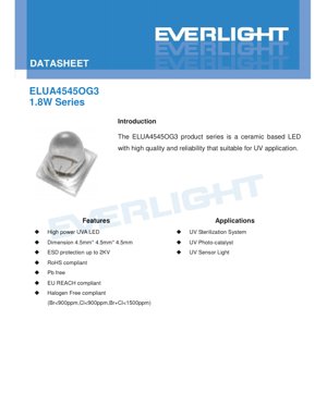
The ELUA4545OG3 product series represents a high-reliability, ceramic-based light-emitting diode (LED) engineered specifically for ultraviolet-A (UVA) applications. Its core construction utilizes an Al2O3 (aluminum oxide) ceramic package, which offers superior thermal management and mechanical stability compared to traditional plastic packages. This makes the series particularly suitable for demanding environments where consistent optical output and long-term reliability are critical.
The primary advantage of this series lies in its combination of high radiant flux output within a compact 4.5mm x 4.5mm footprint. It is designed to operate at a forward current of 500mA, delivering a typical optical power that classifies it as a 1.8W-class device. The series incorporates essential protection features, including ESD protection rated up to 2KV (Human Body Model), ensuring robustness during handling and assembly. Furthermore, the product is compliant with major environmental and safety directives, being RoHS compliant, Pb-free, EU REACH compliant, and halogen-free (with strict limits on Bromine and Chlorine content).
The target market for the ELUA4545OG3 includes manufacturers of UV sterilization systems, where UVA light is used to inactivate microorganisms; UV photocatalyst systems, which use UVA to activate photocatalytic materials for air or water purification; and various UV sensor and curing applications.
2. Technical Parameter Deep Dive
2.1 Absolute Maximum Ratings
The device's operational limits are defined by its Absolute Maximum Ratings. The maximum permissible DC forward current (IF) is 1000mA for the 385nm, 395nm, and 405nm wavelength variants. For the 365nm variant, the maximum IF is derated to 700mA, reflecting typical material characteristics at shorter wavelengths. The maximum junction temperature (TJ) is 105°C, while the recommended operating temperature range (TOpr) is from -10°C to +100°C. The thermal resistance from junction to solder point (Rth) is specified as 4°C/W, a key parameter for heatsink design.
2.2 Photometric and Electrical Characteristics
The series is offered in four peak wavelength groups: 360-370nm, 380-390nm, 390-400nm, and 400-410nm. For the 360-370nm (365nm typical) variant, the minimum radiant flux is 900mW, typical is 1200mW, and maximum is 1500mW when driven at IF=500mA. For the other three wavelength groups (385nm, 395nm, 405nm typical), the minimum radiant flux is higher at 1000mW, with typical and maximum values of 1250mW and 1500mW, respectively. The forward voltage (VF) for all variants under this condition ranges from 3.2V to 4.1V.
3. Binning System Explanation
The product is classified according to a precise binning system to ensure consistency in application design.
3.1 Radiant Flux Binning
Radiant flux is binned separately for the 365nm group and the 385-405nm groups. For the 365nm LEDs, bins U1, U2, and U3 cover ranges of 900-1100mW, 1100-1300mW, and 1300-1500mW, respectively. For the 385-405nm LEDs, bins U2, U3, and U4 cover 1000-1200mW, 1200-1400mW, and 1400-1500mW, respectively. Measurement tolerance is ±10%.
3.2 Peak Wavelength Binning
Peak wavelength is grouped into four bins: U36 (360-370nm), U38 (380-390nm), U39 (390-400nm), and U40 (400-410nm). The measurement tolerance is ±1nm.
3.3 Forward Voltage Binning
Forward voltage at IF=500mA is binned into three categories: 3235 (3.2-3.5V), 3538 (3.5-3.8V), and 3841 (3.8-4.1V). The measurement tolerance is ±2%.
4. Performance Curve Analysis
4.1 Spectrum and Relative Radiant Flux
The spectral distribution curves show characteristic narrow emission peaks for each wavelength group (365nm, 385nm, 395nm, 405nm). The relative radiant flux vs. forward current graph demonstrates a near-linear relationship up to the rated 500mA, with the 405nm variant showing the highest relative output and the 365nm variant the lowest at a given current, which is expected due to photon energy differences.
4.2 Thermal Characteristics
The relative radiant flux vs. ambient temperature curve shows output decreasing as temperature increases, a common behavior for LEDs. The derating curve is crucial for design: it dictates the maximum allowable forward current as a function of the ambient temperature (at the thermal pad) to ensure the junction temperature does not exceed 105°C. For example, at an ambient temperature of 85°C, the maximum current for the 365nm LED is significantly reduced to maintain reliability.
4.3 Forward Voltage and Peak Wavelength Drift
The forward voltage vs. forward current curve shows the typical diode behavior. The forward voltage vs. ambient temperature curve indicates a negative temperature coefficient, where VF decreases slightly as temperature rises. The peak wavelength also shifts with both current and temperature, typically increasing (red-shifting) with higher temperature.
5. Mechanical and Package Information
5.1 Mechanical Dimensions
The LED has a square ceramic body measuring 4.5mm in length, 4.5mm in width, and 4.5mm in height, with a tolerance of ±0.1mm unless otherwise specified. The package includes a thermal pad on the bottom for efficient heat transfer to the printed circuit board (PCB).
5.2 Pad Configuration and Polarity
The device features surface-mount pads. The pad layout diagram clearly identifies the anode (+) and cathode (-) electrical connections, as well as the thermal pad. Correct polarity must be observed during assembly to prevent device damage.
6. Soldering and Assembly Guidelines
The ELUA4545OG3 is suitable for standard SMT (Surface Mount Technology) processes, including reflow soldering. Critical guidelines include: the reflow soldering profile must be carefully controlled; the process should not be performed more than twice on the same device; mechanical stress on the LED during heating and cooling must be avoided; and the PCB should not be bent after soldering to prevent cracking of the ceramic package or solder joints. The specific reflow temperature profile should follow industry standards for similar ceramic components.
7. Ordering Information and Model Nomenclature
The product nomenclature follows a detailed coding system: ELUA4545OG3-PXXXXYY3241500-VD1M. Key elements include: \"EL\" for the manufacturer, \"UA\" for UVA, \"4545\" for package size, \"O\" for Al2O3 ceramic, \"G\" for Ag coating. \"PXXXX\" defines the wavelength range (e.g., 6070 for 360-370nm). \"YY\" defines the minimum radiant flux bin code. \"3241\" specifies the forward voltage range (3.2-4.1V). \"500\" indicates the forward current rating (500mA). The suffix details the chip type (Vertical), size (45mil), quantity (1), and process (Molding).
8. Application Suggestions
8.1 Typical Application Scenarios
- UV Sterilization Systems: Used in air purifiers, water disinfection units, and surface sanitizers. The 365nm and 385nm wavelengths are common for triggering photocatalytic reactions or directly affecting certain microorganisms.
- UV Photocatalyst Activation: Essential in systems using titanium dioxide (TiO2) or other catalysts for breaking down volatile organic compounds (VOCs) or odors.
- UV Curing: For adhesives, inks, and coatings that polymerize under UVA light.
- Sensor Excitation: As a light source for fluorescence or phosphorescence-based sensors.
8.2 Design Considerations
- Thermal Management: Due to the 1.8W power dissipation, a properly designed PCB with adequate thermal vias and possibly an external heatsink is mandatory to maintain junction temperature within limits, especially in high-ambient-temperature environments.
- Current Drive: A constant current driver is recommended to ensure stable optical output and longevity. The drive current should be selected based on the required radiant flux and the thermal derating curve.
- Optics: UVA light is not visible to the human eye. Appropriate safety measures (enclosures, warnings) must be implemented, as prolonged exposure can be harmful. Optical lenses or reflectors may be needed to direct the radiation.
- ESD Protection: While the device has built-in ESD protection, standard ESD handling precautions during assembly are still advised.
9. Technical Comparison and Differentiation
The ELUA4545OG3 differentiates itself through its ceramic package. Compared to plastic-packaged UVA LEDs, the ceramic package offers significantly lower thermal resistance, enabling higher drive currents and better performance stability over time and temperature. The 4.5mm footprint provides a high power density. The inclusion of multiple, tightly defined bins for wavelength, flux, and voltage allows for precise system design and tighter performance matching in multi-LED arrays, which is critical for uniform irradiation in sterilization or curing applications.
10. Frequently Asked Questions (Based on Technical Parameters)
Q: Why is the maximum current lower for the 365nm version?
A: The semiconductor materials used for generating shorter wavelength photons (like 365nm) typically have different electrical and thermal properties, often resulting in a lower maximum current rating to ensure long-term reliability and prevent accelerated degradation.
Q: How do I select the right bin for my application?
A: For applications requiring specific irradiation intensity, choose a higher radiant flux bin (e.g., U3/U4). For applications sensitive to exact wavelength (e.g., matching a photocatalyst's activation peak), select the appropriate wavelength bin (U36, U38, etc.). For power supply design, a tighter forward voltage bin can simplify current regulation.
Q: Can I drive this LED with a voltage source?
A: It is strongly discouraged. LEDs are current-driven devices. Their forward voltage has a negative temperature coefficient and varies from unit to unit. Driving with a constant voltage source can lead to thermal runaway and catastrophic failure. Always use a constant current driver.
11. Practical Design Case Study
Consider designing a UV curing module for a small 3D printer resin tank. The goal is to achieve uniform curing across a 10cm x 10cm area. A designer might select the ELUA4545OG3-P9000U33241500-VD1M (390-400nm wavelength, U3 flux bin). An array of 16 LEDs (4x4) could be planned. Based on the derating curve and assuming a module ambient temperature of 50°C, the designer determines a safe drive current of 450mA per LED. Using the typical radiant flux of 1250mW at 500mA and extrapolating from the relative flux curve for 450mA, the expected optical power per LED is calculated. The total UV irradiance on the target area is then modeled, considering the radiation pattern and distance. The PCB is designed with a 2oz copper layer and an array of thermal vias under each LED's thermal pad connected to a large bottom-side copper pour, ensuring the thermal resistance from junction to ambient is low enough to keep TJ below 105°C. A constant current driver capable of delivering 7.2A (16 * 0.45A) is selected.
12. Operating Principle Introduction
UVA LEDs operate on the same fundamental principle as visible LEDs: electroluminescence in a semiconductor p-n junction. When a forward voltage is applied, electrons and holes are injected into the active region where they recombine, releasing energy in the form of photons. The wavelength (color) of the emitted light is determined by the bandgap energy of the semiconductor materials used in the active region. For UVA light (wavelengths ~315-400nm), materials like aluminum gallium nitride (AlGaN) or indium gallium nitride (InGaN) with specific compositions are used to achieve the desired bandgap. The ceramic package primarily serves as a robust mechanical substrate with excellent thermal conductivity to dissipate the heat generated from non-radiative recombination and electrical losses, thereby maintaining efficiency and lifespan.
13. Technology Trends
The UVA LED market is driven by demand for mercury-free UV sources, leading to trends towards higher wall-plug efficiency (more optical power per electrical watt), increased power density from smaller packages, and longer operational lifetimes. There is ongoing research into novel semiconductor materials and structures to improve efficiency, particularly at the shorter UVA and UVB wavelengths. Additionally, integration with smart drivers and sensors for closed-loop intensity control is becoming more common in advanced applications. The push for sustainability continues to emphasize RoHS and halogen-free compliance across the industry.
LED Specification Terminology
Complete explanation of LED technical terms
Photoelectric Performance
| Term | Unit/Representation | Simple Explanation | Why Important |
|---|---|---|---|
| Luminous Efficacy | lm/W (lumens per watt) | Light output per watt of electricity, higher means more energy efficient. | Directly determines energy efficiency grade and electricity cost. |
| Luminous Flux | lm (lumens) | Total light emitted by source, commonly called "brightness". | Determines if the light is bright enough. |
| Viewing Angle | ° (degrees), e.g., 120° | Angle where light intensity drops to half, determines beam width. | Affects illumination range and uniformity. |
| CCT (Color Temperature) | K (Kelvin), e.g., 2700K/6500K | Warmth/coolness of light, lower values yellowish/warm, higher whitish/cool. | Determines lighting atmosphere and suitable scenarios. |
| CRI / Ra | Unitless, 0–100 | Ability to render object colors accurately, Ra≥80 is good. | Affects color authenticity, used in high-demand places like malls, museums. |
| SDCM | MacAdam ellipse steps, e.g., "5-step" | Color consistency metric, smaller steps mean more consistent color. | Ensures uniform color across same batch of LEDs. |
| Dominant Wavelength | nm (nanometers), e.g., 620nm (red) | Wavelength corresponding to color of colored LEDs. | Determines hue of red, yellow, green monochrome LEDs. |
| Spectral Distribution | Wavelength vs intensity curve | Shows intensity distribution across wavelengths. | Affects color rendering and quality. |
Electrical Parameters
| Term | Symbol | Simple Explanation | Design Considerations |
|---|---|---|---|
| Forward Voltage | Vf | Minimum voltage to turn on LED, like "starting threshold". | Driver voltage must be ≥Vf, voltages add up for series LEDs. |
| Forward Current | If | Current value for normal LED operation. | Usually constant current drive, current determines brightness & lifespan. |
| Max Pulse Current | Ifp | Peak current tolerable for short periods, used for dimming or flashing. | Pulse width & duty cycle must be strictly controlled to avoid damage. |
| Reverse Voltage | Vr | Max reverse voltage LED can withstand, beyond may cause breakdown. | Circuit must prevent reverse connection or voltage spikes. |
| Thermal Resistance | Rth (°C/W) | Resistance to heat transfer from chip to solder, lower is better. | High thermal resistance requires stronger heat dissipation. |
| ESD Immunity | V (HBM), e.g., 1000V | Ability to withstand electrostatic discharge, higher means less vulnerable. | Anti-static measures needed in production, especially for sensitive LEDs. |
Thermal Management & Reliability
| Term | Key Metric | Simple Explanation | Impact |
|---|---|---|---|
| Junction Temperature | Tj (°C) | Actual operating temperature inside LED chip. | Every 10°C reduction may double lifespan; too high causes light decay, color shift. |
| Lumen Depreciation | L70 / L80 (hours) | Time for brightness to drop to 70% or 80% of initial. | Directly defines LED "service life". |
| Lumen Maintenance | % (e.g., 70%) | Percentage of brightness retained after time. | Indicates brightness retention over long-term use. |
| Color Shift | Δu′v′ or MacAdam ellipse | Degree of color change during use. | Affects color consistency in lighting scenes. |
| Thermal Aging | Material degradation | Deterioration due to long-term high temperature. | May cause brightness drop, color change, or open-circuit failure. |
Packaging & Materials
| Term | Common Types | Simple Explanation | Features & Applications |
|---|---|---|---|
| Package Type | EMC, PPA, Ceramic | Housing material protecting chip, providing optical/thermal interface. | EMC: good heat resistance, low cost; Ceramic: better heat dissipation, longer life. |
| Chip Structure | Front, Flip Chip | Chip electrode arrangement. | Flip chip: better heat dissipation, higher efficacy, for high-power. |
| Phosphor Coating | YAG, Silicate, Nitride | Covers blue chip, converts some to yellow/red, mixes to white. | Different phosphors affect efficacy, CCT, and CRI. |
| Lens/Optics | Flat, Microlens, TIR | Optical structure on surface controlling light distribution. | Determines viewing angle and light distribution curve. |
Quality Control & Binning
| Term | Binning Content | Simple Explanation | Purpose |
|---|---|---|---|
| Luminous Flux Bin | Code e.g., 2G, 2H | Grouped by brightness, each group has min/max lumen values. | Ensures uniform brightness in same batch. |
| Voltage Bin | Code e.g., 6W, 6X | Grouped by forward voltage range. | Facilitates driver matching, improves system efficiency. |
| Color Bin | 5-step MacAdam ellipse | Grouped by color coordinates, ensuring tight range. | Guarantees color consistency, avoids uneven color within fixture. |
| CCT Bin | 2700K, 3000K etc. | Grouped by CCT, each has corresponding coordinate range. | Meets different scene CCT requirements. |
Testing & Certification
| Term | Standard/Test | Simple Explanation | Significance |
|---|---|---|---|
| LM-80 | Lumen maintenance test | Long-term lighting at constant temperature, recording brightness decay. | Used to estimate LED life (with TM-21). |
| TM-21 | Life estimation standard | Estimates life under actual conditions based on LM-80 data. | Provides scientific life prediction. |
| IESNA | Illuminating Engineering Society | Covers optical, electrical, thermal test methods. | Industry-recognized test basis. |
| RoHS / REACH | Environmental certification | Ensures no harmful substances (lead, mercury). | Market access requirement internationally. |
| ENERGY STAR / DLC | Energy efficiency certification | Energy efficiency and performance certification for lighting. | Used in government procurement, subsidy programs, enhances competitiveness. |