1. Product Overview
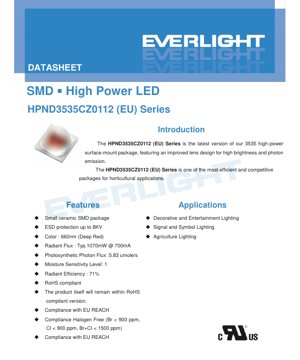
The HPND3535CZ0112 (EU) Series represents the latest iteration of high-power surface-mount LED technology packaged in a compact 3535 ceramic footprint. This series is engineered with an advanced lens design optimized to deliver exceptionally high brightness and superior photon emission efficiency. Primarily targeting the horticultural lighting market, this LED is positioned as one of the most efficient and competitive solutions available for applications requiring specific light spectra to influence plant growth and development. Its core advantages include a robust ceramic substrate for excellent thermal management, integrated ESD protection enhancing reliability, and compliance with stringent environmental and safety standards including RoHS, REACH, and halogen-free requirements.
2. In-Depth Technical Parameter Analysis
2.1 Absolute Maximum Ratings
The device is rated for a maximum continuous forward current (IF) of 700 mA under conditions where the thermal pad temperature is maintained at 25°C. For pulsed operation, a peak pulse current (IPulse) of 1250 mA is permissible under a duty cycle of 1/10 at 1 kHz. The maximum junction temperature (TJ) is 125°C, with an operating temperature range (TOpr) from -40°C to +100°C. The thermal resistance (Rth) from junction to solder point is specified at 8 °C/W, which is critical for thermal design. The component can withstand a maximum soldering temperature (TSol) of 260°C for a limited time during reflow, with a maximum of two allowable reflow cycles to prevent package degradation.
2.2 Photometric and Radiometric Characteristics
The primary color variant is Deep Red, with a peak wavelength (λP) typically at 660 nm, ranging from 655 nm to 665 nm depending on the specific bin. The typical radiant flux (optical power) is 1070 mW when driven at the nominal current of 700 mA, measured at a thermal pad temperature of 25°C. A key performance metric for horticulture is the Photosynthetic Photon Flux (PPF), which is specified at 5.83 μmol/s. The radiant efficiency, indicating the conversion efficiency of electrical power to optical power, is 71%. The viewing angle (2θ1/2) is 120 degrees, providing a wide, Lambertian radiation pattern suitable for broad, even illumination.
2.3 Electrical Characteristics
The forward voltage (Vf) at 700 mA typically falls around 2.15V, with a binning range from 1.75V (U1 bin) to 2.35V (U2 bin). The device offers robust Electrostatic Discharge (ESD) protection, withstanding up to 8000 V (Human Body Model), which is essential for handling and assembly in industrial environments.
3. Binning System Explanation3.1 Radiant Power Binning
The LEDs are sorted into radiant power bins to ensure consistency in light output. The primary grouping for this series includes bins where the minimum radiant power is 1000 mW and the maximum is 1200 mW. This allows designers to select components that meet specific flux requirements for their application.
3.2 Forward Voltage Binning
Forward voltage is binned into two groups: U1 (1.75V - 2.05V) and U2 (2.05V - 2.35V). This binning is defined at the operating current of 700 mA. Knowledge of the Vf bin is crucial for designing the driver circuitry to ensure stable current regulation and predictable power consumption across multiple LEDs in a system.
3.3 Wavelength (Color) Binning
The Deep Red emission is tightly controlled through wavelength binning. The available bins are D5 (655 nm - 660 nm) and D6 (660 nm - 665 nm). This precise control is vital for horticultural applications where specific photon wavelengths trigger different photomorphogenic responses in plants, such as flowering or stem elongation.
4. Performance Curve Analysis
4.1 Spectral Power Distribution
The Relative Spectral Power Distribution (SPD) graph shows a narrow, dominant peak centered around 660 nm with minimal emission in other parts of the spectrum. This monochromatic characteristic is ideal for applications requiring pure deep red light without wasting energy on unused wavelengths. The narrow bandwidth ensures that the emitted photons are highly efficient for driving photosynthesis, which has peak absorption in the red region.
4.2 Current-Voltage (I-V) Characteristics
The typical I-V curve illustrates the relationship between forward current and forward voltage. At the nominal 700 mA drive current, the voltage is approximately 2.15V. The curve shows the expected exponential relationship, and the slope in the operating region informs about the dynamic resistance of the diode, which is important for driver design, especially in constant-current configurations.
5. Mechanical and Package Information
5.1 Mechanical Dimensions
The package follows a standard 3535 footprint, with dimensions of 3.5 mm x 3.5 mm in length and width. The overall height is approximately 1.6 mm. The package features a ceramic substrate which provides excellent thermal conductivity, helping to dissipate heat from the LED junction efficiently. The lens is an integral part of the package, and the datasheet explicitly warns against applying force to it during handling, as this can lead to device failure.
5.2 Pad Configuration and Polarity
The component has three electrical pads: Pad 1 is designated as the Anode (+), Pad 2 is the Cathode (-), and a central 'P' pad is a Thermal Pad. It is critically important to note that the thermal pad is electrically isolated from the anode and cathode. This isolation allows for direct thermal connection to a heatsink or PCB copper pour for cooling without creating an electrical short. Correct polarity must be observed during assembly to prevent damage.
6. Soldering and Assembly Guidelines
6.1 Reflow Soldering Profile
The component is designed for standard Surface-Mount Technology (SMT) processes using lead-free (Pb-free) solder. A detailed reflow profile is provided: Preheat from 25°C to 150°C at a rate of 2-3°C/sec, maintain between 150°C and 200°C for 60-120 seconds, then ramp to a peak temperature not exceeding 260°C. The time above the liquidus temperature (217°C) should be 60-90 seconds, and the time within 5°C of the peak temperature should be 20-40 seconds. The maximum ramp-down rate is 3-5°C/sec.
6.2 Critical Assembly Notes
The device has a Moisture Sensitivity Level (MSL) of 1, meaning it has an unlimited floor life at conditions ≤30°C / 85% Relative Humidity and does not require baking before use if stored properly. However, it is strongly recommended that reflow soldering is performed no more than two times to avoid thermal stress on the package and internal bonds. After soldering, the printed circuit board (PCB) should not be bent, as mechanical stress can fracture the solder joints or the ceramic package itself.
7. Packaging and Ordering Information
The product is identified by a comprehensive part number that encodes its key characteristics. An example order code is provided: HPND3535CZ0112-NDR55651K0X24700-4H(EU). This code specifies the series, the deep red color (NDR), the radiant power bin, the wavelength bin (D5/D6), the forward voltage bin (U1/U2), the drive current (700mA), and compliance marking (EU). Designers must use the full order code to ensure they receive the exact combination of performance bins required for their application.
8. Application Recommendations
8.1 Primary Application Scenarios
Horticultural Lighting: This is the primary application. The 660nm deep red light is crucial for the photosynthesis process, particularly for driving the photosystem II reaction. It is used in greenhouse supplemental lighting, vertical farms, and plant growth chambers to accelerate growth, control flowering, and increase yield.
Decorative and Entertainment Lighting: The pure, saturated red color is suitable for architectural accent lighting, stage lighting, and themed entertainment venues where specific color points are required.
Signal and Symbol Lighting: Can be used in status indicators, exit signs, or other applications where a high-brightness, reliable red light source is needed.
8.2 Design Considerations
Thermal Management: With a thermal resistance of 8 °C/W and a maximum junction temperature of 125°C, effective heat sinking is paramount. The thermally isolated pad must be connected to a sufficiently large copper area on the PCB or to a dedicated heatsink using thermally conductive but electrically insulating materials if necessary. Inadequate cooling will lead to reduced light output, accelerated lumen depreciation, and potential premature failure.
Drive Current: While rated for 700 mA, operating at lower currents can significantly improve efficacy (lumens per watt or μmol/J) and longevity. The driver should be a constant-current type, matched to the forward voltage bin of the LEDs used, to ensure stable and uniform performance.
Optical Design: The 120-degree viewing angle provides wide coverage. For applications requiring more focused beams, secondary optics such as reflectors or lenses may be employed.
9. Technical Comparison and Differentiation
The HPND3535CZ0112 (EU) Series differentiates itself in the high-power LED market through several key features. The use of a ceramic package, as opposed to plastic, offers superior thermal performance and long-term reliability, especially under high-drive conditions common in horticulture. The high radiant efficiency of 71% translates to less wasted energy as heat, allowing for more compact fixture designs. The combination of high PPF (5.83 μmol/s) at a standard 700mA drive current and precise wavelength targeting around 660nm makes it particularly optimized for photosynthetic efficiency, often outperforming broader-spectrum or less efficient red LEDs in dedicated grow light applications.
10. Frequently Asked Questions (FAQ)
Q: What is the difference between radiant flux (mW) and Photosynthetic Photon Flux (PPF)?
A: Radiant flux measures the total optical power emitted in watts. PPF measures the number of photosynthetically active photons (in the 400-700 nm range) emitted per second, in micromoles per second (μmol/s). PPF is the relevant metric for plant growth, while radiant flux describes total light power.
Q: Can I drive this LED with a constant voltage source?
A: No. LEDs are current-driven devices. Their forward voltage has a negative temperature coefficient and varies from unit to unit (as seen in the binning). A constant voltage source can lead to thermal runaway and destruction of the LED. Always use a constant-current driver.
Q: Why is the thermal pad electrically isolated?
A: Electrical isolation allows the pad to be directly soldered to a large copper plane on the PCB for maximum heat dissipation without creating an electrical short circuit between the anode and cathode. This simplifies thermal design and improves cooling efficiency.
Q: How does the 660nm wavelength benefit plants compared to other reds?
A: Chlorophyll absorption peaks in the red and blue regions of the spectrum. The 660nm wavelength aligns closely with a major peak for chlorophyll a and b, making it highly efficient for driving the light reactions of photosynthesis, influencing phytochrome-mediated processes like flowering.
11. Practical Application Case Study
Scenario: Designing a Supplemental Lighting Module for Leafy Greens in a Vertical Farm.
A lighting engineer is designing a narrow-profile LED bar to be mounted between tiers of a vertical farm growing lettuce. The goal is to provide intense, energy-efficient light to maximize growth rate in a confined space.
Design Choices: The engineer selects the HPND3535CZ0112 (EU) Series for its high PPF output and 660nm wavelength, which is ideal for promoting leafy growth. They choose components from the higher radiant power bin (S3, 1100-1200mW) to maximize light intensity. A dense array of these LEDs is placed on an aluminum-core PCB (MCPCB) to effectively manage the thermal load from the 700mA drive current. The wide 120-degree beam angle ensures even light distribution across the plant canopy without the need for additional optics, keeping the module slim. The driver is selected as a constant-current type capable of delivering the required current while accepting the input voltage range of the farm's power system. The result is a compact, high-output light bar that delivers photons efficiently where they are most needed for photosynthesis.
12. Technical Principle Introduction
Light Emitting Diodes (LEDs) are semiconductor devices that emit light when an electric current passes through them. This phenomenon, called electroluminescence, occurs when electrons recombine with electron holes within the device, releasing energy in the form of photons. The color of the light (its wavelength) is determined by the energy band gap of the semiconductor material used. For deep red LEDs like the HPND3535CZ0112, materials such as Aluminum Gallium Indium Phosphide (AlGaInP) are typically used to achieve the 660nm emission. The ceramic package serves as both a protective enclosure and a critical thermal path, conducting heat away from the tiny semiconductor chip (the junction) to the external environment, thereby maintaining performance and reliability.
13. Technology Trends and Developments
The horticultural lighting sector is driving significant advancements in LED technology. The trend is moving towards even higher photon efficacies (μmol/J), reducing the electricity cost per unit of plant growth. There is also a focus on developing LEDs with specific spectral outputs beyond simple deep red and blue, including far-red (730nm) to influence plant morphology and flowering, and ultraviolet wavelengths for pest/disease control. Improved package designs continue to lower thermal resistance, allowing for higher drive currents and greater light output from a single emitter. Furthermore, the integration of multiple monochromatic chips (e.g., red, blue, far-red) into a single package to create a bespoke spectrum is an area of active development, offering lighting designers unprecedented control over the light recipe for different crops and growth stages.
LED Specification Terminology
Complete explanation of LED technical terms
Photoelectric Performance
| Term | Unit/Representation | Simple Explanation | Why Important |
|---|---|---|---|
| Luminous Efficacy | lm/W (lumens per watt) | Light output per watt of electricity, higher means more energy efficient. | Directly determines energy efficiency grade and electricity cost. |
| Luminous Flux | lm (lumens) | Total light emitted by source, commonly called "brightness". | Determines if the light is bright enough. |
| Viewing Angle | ° (degrees), e.g., 120° | Angle where light intensity drops to half, determines beam width. | Affects illumination range and uniformity. |
| CCT (Color Temperature) | K (Kelvin), e.g., 2700K/6500K | Warmth/coolness of light, lower values yellowish/warm, higher whitish/cool. | Determines lighting atmosphere and suitable scenarios. |
| CRI / Ra | Unitless, 0–100 | Ability to render object colors accurately, Ra≥80 is good. | Affects color authenticity, used in high-demand places like malls, museums. |
| SDCM | MacAdam ellipse steps, e.g., "5-step" | Color consistency metric, smaller steps mean more consistent color. | Ensures uniform color across same batch of LEDs. |
| Dominant Wavelength | nm (nanometers), e.g., 620nm (red) | Wavelength corresponding to color of colored LEDs. | Determines hue of red, yellow, green monochrome LEDs. |
| Spectral Distribution | Wavelength vs intensity curve | Shows intensity distribution across wavelengths. | Affects color rendering and quality. |
Electrical Parameters
| Term | Symbol | Simple Explanation | Design Considerations |
|---|---|---|---|
| Forward Voltage | Vf | Minimum voltage to turn on LED, like "starting threshold". | Driver voltage must be ≥Vf, voltages add up for series LEDs. |
| Forward Current | If | Current value for normal LED operation. | Usually constant current drive, current determines brightness & lifespan. |
| Max Pulse Current | Ifp | Peak current tolerable for short periods, used for dimming or flashing. | Pulse width & duty cycle must be strictly controlled to avoid damage. |
| Reverse Voltage | Vr | Max reverse voltage LED can withstand, beyond may cause breakdown. | Circuit must prevent reverse connection or voltage spikes. |
| Thermal Resistance | Rth (°C/W) | Resistance to heat transfer from chip to solder, lower is better. | High thermal resistance requires stronger heat dissipation. |
| ESD Immunity | V (HBM), e.g., 1000V | Ability to withstand electrostatic discharge, higher means less vulnerable. | Anti-static measures needed in production, especially for sensitive LEDs. |
Thermal Management & Reliability
| Term | Key Metric | Simple Explanation | Impact |
|---|---|---|---|
| Junction Temperature | Tj (°C) | Actual operating temperature inside LED chip. | Every 10°C reduction may double lifespan; too high causes light decay, color shift. |
| Lumen Depreciation | L70 / L80 (hours) | Time for brightness to drop to 70% or 80% of initial. | Directly defines LED "service life". |
| Lumen Maintenance | % (e.g., 70%) | Percentage of brightness retained after time. | Indicates brightness retention over long-term use. |
| Color Shift | Δu′v′ or MacAdam ellipse | Degree of color change during use. | Affects color consistency in lighting scenes. |
| Thermal Aging | Material degradation | Deterioration due to long-term high temperature. | May cause brightness drop, color change, or open-circuit failure. |
Packaging & Materials
| Term | Common Types | Simple Explanation | Features & Applications |
|---|---|---|---|
| Package Type | EMC, PPA, Ceramic | Housing material protecting chip, providing optical/thermal interface. | EMC: good heat resistance, low cost; Ceramic: better heat dissipation, longer life. |
| Chip Structure | Front, Flip Chip | Chip electrode arrangement. | Flip chip: better heat dissipation, higher efficacy, for high-power. |
| Phosphor Coating | YAG, Silicate, Nitride | Covers blue chip, converts some to yellow/red, mixes to white. | Different phosphors affect efficacy, CCT, and CRI. |
| Lens/Optics | Flat, Microlens, TIR | Optical structure on surface controlling light distribution. | Determines viewing angle and light distribution curve. |
Quality Control & Binning
| Term | Binning Content | Simple Explanation | Purpose |
|---|---|---|---|
| Luminous Flux Bin | Code e.g., 2G, 2H | Grouped by brightness, each group has min/max lumen values. | Ensures uniform brightness in same batch. |
| Voltage Bin | Code e.g., 6W, 6X | Grouped by forward voltage range. | Facilitates driver matching, improves system efficiency. |
| Color Bin | 5-step MacAdam ellipse | Grouped by color coordinates, ensuring tight range. | Guarantees color consistency, avoids uneven color within fixture. |
| CCT Bin | 2700K, 3000K etc. | Grouped by CCT, each has corresponding coordinate range. | Meets different scene CCT requirements. |
Testing & Certification
| Term | Standard/Test | Simple Explanation | Significance |
|---|---|---|---|
| LM-80 | Lumen maintenance test | Long-term lighting at constant temperature, recording brightness decay. | Used to estimate LED life (with TM-21). |
| TM-21 | Life estimation standard | Estimates life under actual conditions based on LM-80 data. | Provides scientific life prediction. |
| IESNA | Illuminating Engineering Society | Covers optical, electrical, thermal test methods. | Industry-recognized test basis. |
| RoHS / REACH | Environmental certification | Ensures no harmful substances (lead, mercury). | Market access requirement internationally. |
| ENERGY STAR / DLC | Energy efficiency certification | Energy efficiency and performance certification for lighting. | Used in government procurement, subsidy programs, enhances competitiveness. |