1. Product Overview
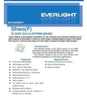
The Shwo(F) series represents the latest iteration of a high-power surface-mount LED package in the 3535 footprint. It is engineered with an enhanced lens design specifically to achieve superior brightness and photon emission efficiency. This series is positioned as one of the most efficient and competitive solutions available for specialized lighting applications, with a primary focus on horticulture.
The name \"Shwo\" is derived from the Chinese word for \"Twinkle,\" symbolizing the bright, compact, and star-like quality of this LED package. Its core advantages include a compact ceramic SMD construction, integrated ESD protection, and compliance with major environmental and safety standards including RoHS, EU REACH, and Halogen-Free requirements.
2. In-Depth Technical Parameter Analysis
2.1 Absolute Maximum Ratings
These parameters define the operational limits beyond which permanent damage to the LED may occur. They are not intended for normal operation.
- Maximum DC Forward Current (IF): 1000 mA (at a duty cycle of 1/10 @ 1 kHz).
- Maximum Peak Pulse Current (IPulse): 1250 mA.
- Maximum ESD Resistance (HBM): 8000 V, providing robust handling protection.
- Reverse Voltage (VR): The LEDs are not designed for reverse bias operation. Applying reverse voltage can cause immediate failure.
- Thermal Resistance (Rth): Ranges from 10°C/W to 12°C/W depending on the chip technology, indicating how effectively heat is transferred from the junction to the thermal pad.
- Maximum Junction Temperature (TJ): 125°C. Exceeding this temperature will drastically reduce lifetime and can cause catastrophic failure.
- Operating Temperature (TOpr): -40°C to +100°C, defining the ambient temperature range for reliable operation.
- Max. Soldering Temperature (TSol): 260°C, compliant with standard lead-free reflow profiles.
- Max. Allowable Reflow Cycles: 2 cycles, indicating the number of times the component can undergo reflow soldering.
2.2 Optical & Electrical Characteristics
These are the typical performance parameters measured under specified test conditions (Tpad = 25°C, IF = 700 mA).
- Color & Wavelength: Royal Blue with a dominant wavelength of 452.5 nm. This wavelength is highly effective for stimulating chlorophyll absorption and is crucial for plant growth in horticultural applications.
- Radiant Flux (Optical Power): Typical value is 1500 mW. The minimum guaranteed radiant flux is 1300 mW.
- Photosynthetic Photon Flux (PPF): 5.28 µmol/s. This metric quantifies the number of photosynthetically active photons emitted per second, directly relevant for horticultural efficacy.
- Radiant Efficiency: 57.1%. This is calculated as (Radiant Flux / Electrical Input Power) and is a key indicator of the LED's electro-optical conversion performance.
- Viewing Angle: Typical 120°, providing a wide radiation pattern suitable for broad area illumination.
2.3 Thermal and Reliability Specifications
- Moisture Sensitivity Level (MSL): Level 1. This is the most robust level, indicating an unlimited floor life at ≤30°C/85% RH and no mandatory baking before reflow soldering, which simplifies inventory management.
- Storage Conditions: -40°C to +100°C. Proper storage within this range is essential to maintain solderability and performance.
3. Binning System Explanation
The product nomenclature follows a detailed coding system: ELSWF – ABCDE – FGHIJ – V1234.
- AB: Represents the minimum luminous flux (lm) or radiant flux (mW) performance bin.
- C: Indicates the radiation pattern (e.g., \"1\" for Lambertian).
- D: Denotes the color (e.g., \"L\" for Royal Blue, 445-460nm).
- E: Specifies power consumption (e.g., \"2\" for 2W).
- H: Defines the packaging type (e.g., \"P\" for Tape).
- V1234: Encodes the forward voltage bin and the color/CCT bin.
For example, the part number ELSWF-S41L2-6FPNM-DB4B6 decodes to a Shwo(F) LED with an S41 radiant flux bin, Lambertian pattern (1), Royal Blue color (L), 2W power (2), supplied on tape (P), with specific forward voltage and color bins DB4B6.
4. Performance Curve Analysis
While the provided PDF excerpt lists these curves in the table of contents, the specific graph data is not included in the given text. Typically, such a datasheet would contain the following essential performance plots:
- Light Output vs. Thermal Pad Temperature: This curve shows how radiant flux decreases as the LED's thermal pad temperature increases. Effective thermal management is critical to maintain output.
- Relative Luminous/Radiance Flux vs. Forward Current: Illustrates the sub-linear relationship between drive current and light output, highlighting efficiency roll-off at higher currents.
- Forward Voltage vs. Forward Current (I-V Curve): Essential for driver design, showing the voltage required to achieve a target current.
- Wavelength vs. Forward Current: Shows any shift in dominant wavelength with changing drive current.
- Spectral Power Distribution: A graph plotting radiant power against wavelength, defining the color characteristics of the Royal Blue emission.
- Current Derating Curves: Graphs specifying the maximum allowable forward current as a function of the thermal pad temperature to ensure TJ is not exceeded.
- Radiation Patterns: Polar diagrams showing the spatial distribution of light intensity (e.g., Lambertian).
5. Mechanical & Packaging Information
5.1 Mechanical Dimensions
The LED utilizes a 3535 surface-mount package (3.5mm x 3.5mm footprint). The detailed mechanical drawing in the datasheet provides precise dimensions for the package body, lens height, and tolerances, which are critical for PCB layout and optical design.
5.2 Pad Configuration & Polarity
The footprint diagram shows the anode and cathode pad layout. Correct polarity is vital for operation. The thermal pad design is crucial for heat dissipation; the datasheet specifies the recommended solder paste stencil pattern and coverage for this pad to ensure optimal thermal transfer to the PCB.
6. Soldering & Assembly Guidelines
- Reflow Soldering: The component is rated for a maximum peak soldering temperature of 260°C, compatible with standard lead-free (SnAgCu) reflow profiles. A maximum of 2 reflow cycles is permitted.
- Handling: Despite its high ESD rating (8kV), standard ESD precautions should be observed during handling and assembly.
- Storage: As an MSL Level 1 device, no specific dry packing or baking is required under standard factory conditions (<30°C/85% RH).
7. Packaging & Ordering Information
The LEDs are available in standard industry packaging:
- Emitter Tape Packaging: Components are placed in embossed carrier tape for automated pick-and-place assembly.
- Emitter Reel Packaging: The tape is wound onto reels. The datasheet specifies the quantity per reel, tape width, pocket spacing, and reel dimensions.
- Product Labeling: Reels and boxes are labeled with the part number, quantity, date code, and other traceability information.
8. Application Recommendations
8.1 Typical Application Scenarios
- Horticulture Lighting: Primary application. The 452.5nm Royal Blue wavelength is optimal for promoting vegetative growth, controlling plant morphology, and enhancing secondary metabolite production in controlled environment agriculture (CEA), vertical farms, and greenhouse supplementation.
- Decorative and Entertainment Lighting: Used in architectural lighting, stage lighting, and themed environments where saturated blue effects are desired.
- Signal and Symbol Lighting: Suitable for backlighting indicators, signage, and other applications requiring a high-intensity blue light source.
8.2 Design Considerations
- Thermal Management: This is the most critical design factor. With a thermal resistance of ~10-12°C/W, a high-quality thermal path from the thermal pad to the heatsink is mandatory. Use a PCB with sufficient thermal vias and possibly a metal-core board (MCPCB) or insulated metal substrate (IMS) for high-power applications. Maintain the thermal pad temperature as low as possible for maximum light output and longevity.
- Electrical Drive: Use a constant-current LED driver. The typical operating current is 700mA, but designs should refer to the derating curves based on the expected operating temperature. Ensure the driver is compatible with the forward voltage range of the selected bin.
- Optical Design: The 120° Lambertian pattern is suitable for broad coverage. Secondary optics (lenses, reflectors) may be used to collimate or shape the beam for specific applications.
9. Technical Comparison & Differentiation
While a direct side-by-side comparison with other products is not provided in the datasheet, key differentiating features of the Shwo(F) series can be inferred:
- High Radiant Efficiency (57.1%): Indicates excellent conversion of electrical power to useful optical power (Royal Blue photons), which translates to lower energy consumption and reduced thermal load for a given light output in horticulture.
- Integrated 8kV ESD Protection: Offers superior robustness compared to many LEDs without built-in protection, reducing failure rates in manufacturing and field use.
- Ceramic Package: Provides better thermal performance and long-term reliability compared to plastic packages, especially under high-power drive and thermal cycling.
- Comprehensive Compliance: Meets RoHS, REACH, and Halogen-Free standards, facilitating use in global markets with strict environmental regulations.
10. Frequently Asked Questions (Based on Technical Parameters)
Q: What is the difference between Radiant Flux (mW) and Photosynthetic Photon Flux (PPF)?
A: Radiant Flux measures the total optical power emitted in watts. PPF measures the number of photons per second within the photosynthetically active radiation (PAR, 400-700nm) range that are usable by plants. For a monochromatic Royal Blue LED, they are directly correlated, but PPF is the preferred metric for horticultural efficacy.
Q: Can I drive this LED at 1000mA continuously?
A: No. The Absolute Maximum Rating of 1000mA is specified at a 1/10 duty cycle. For continuous operation (DC), you must use the derating curves. At a typical thermal pad temperature of 85°C, the maximum allowable continuous current will be significantly lower than 1000mA to keep the junction temperature below 125°C.
Q: Why is the Moisture Sensitivity Level (MSL 1) important?
A: MSL 1 means the component is not susceptible to moisture-induced damage (\"popcorning\") during reflow soldering. It does not require dry-bag packaging or baking prior to use, simplifying logistics and manufacturing processes compared to higher MSL components (e.g., MSL 2a, 3).
Q: How do I interpret the part number for ordering?
A: You must specify the complete part number, such as ELSWF-S41L2-6FPNM-DB4B6, which defines all key characteristics: flux bin, color, power, packaging, and electrical bins. Ordering by a generic series name is insufficient.
11. Practical Design and Usage Case
Case: Designing a LED Module for Seedling Propagation
A grow light manufacturer is designing a compact module to promote strong, compact seedling growth. They select the Shwo(F) Royal Blue LED for its targeted wavelength.
- Electrical Design: Targeting a PPF of 50 µmol/s per module, they calculate they need approximately 10 LEDs (50 / 5.28 ≈ 9.5). They choose to drive each LED at 700mA from a constant-current driver. They select a part number bin with a forward voltage (Vf) that matches their driver's output voltage range when 10 LEDs are connected in series.
- Thermal Design: The module will be passively cooled. They design an aluminum MCPCB with a thick copper layer and an array of thermal vias under each LED's thermal pad. They model the expected thermal pad temperature to be 75°C in the final fixture. Consulting the derating curve for 75°C, they confirm that 700mA operation is within the safe operating area.
- Mechanical & Optical Design: The LEDs are placed on a 3.5mm grid. Given the 120° beam angle, no secondary optics are used, as broad, even coverage is desired over the seedling tray.
- Result: The module provides the targeted blue spectrum efficiently, promoting healthy seedling development without excessive stem elongation, while reliable thermal design ensures long-term performance.
12. Operational Principle Introduction
The Shwo(F) LED is a semiconductor light source based on indium gallium nitride (InGaN) material technology. When a forward voltage is applied across the anode and cathode, electrons and holes are injected into the active region of the semiconductor chip. They recombine, releasing energy in the form of photons. The specific composition of the InGaN quantum well structure determines the wavelength of the emitted light—in this case, Royal Blue at approximately 452.5 nm. The ceramic package provides mechanical support, electrical connections, and a primary lens that shapes the light output into a Lambertian pattern. The integrated ESD protection diode safeguards the sensitive semiconductor junction from electrostatic discharge events.
13. Technology Trends and Developments
The development of LEDs like the Shwo(F) series is driven by several key trends in the industry:
- Increased Efficiency (lm/W or Radiant Efficiency): Ongoing materials science and chip design improvements continue to push the wall-plug efficiency higher, reducing energy consumption and thermal management demands for the same light output.
- Higher Power Density: Packages like the 3535 are being driven at higher currents to deliver more light from a smaller area, enabling more compact and intense lighting fixtures.
- Application-Specific Optimization: Rather than general-purpose white LEDs, there is a strong trend towards LEDs optimized for specific spectral bands. Horticulture is a prime example, with LEDs tailored to precise wavelengths that match plant photoreceptors (e.g., Royal Blue for chlorophyll absorption, Far-Red for phytochrome response).
- Improved Reliability and Robustness: Features like high ESD ratings, ceramic packaging, and moisture-resistant designs are becoming standard for professional-grade components, ensuring longer lifetimes in demanding applications.
- Integration and Standardization:** The use of standard footprints (e.g., 3535) and packaging simplifies design and allows for second-source compatibility, while integrated protection circuits add value and reliability.
LED Specification Terminology
Complete explanation of LED technical terms
Photoelectric Performance
| Term | Unit/Representation | Simple Explanation | Why Important |
|---|---|---|---|
| Luminous Efficacy | lm/W (lumens per watt) | Light output per watt of electricity, higher means more energy efficient. | Directly determines energy efficiency grade and electricity cost. |
| Luminous Flux | lm (lumens) | Total light emitted by source, commonly called "brightness". | Determines if the light is bright enough. |
| Viewing Angle | ° (degrees), e.g., 120° | Angle where light intensity drops to half, determines beam width. | Affects illumination range and uniformity. |
| CCT (Color Temperature) | K (Kelvin), e.g., 2700K/6500K | Warmth/coolness of light, lower values yellowish/warm, higher whitish/cool. | Determines lighting atmosphere and suitable scenarios. |
| CRI / Ra | Unitless, 0–100 | Ability to render object colors accurately, Ra≥80 is good. | Affects color authenticity, used in high-demand places like malls, museums. |
| SDCM | MacAdam ellipse steps, e.g., "5-step" | Color consistency metric, smaller steps mean more consistent color. | Ensures uniform color across same batch of LEDs. |
| Dominant Wavelength | nm (nanometers), e.g., 620nm (red) | Wavelength corresponding to color of colored LEDs. | Determines hue of red, yellow, green monochrome LEDs. |
| Spectral Distribution | Wavelength vs intensity curve | Shows intensity distribution across wavelengths. | Affects color rendering and quality. |
Electrical Parameters
| Term | Symbol | Simple Explanation | Design Considerations |
|---|---|---|---|
| Forward Voltage | Vf | Minimum voltage to turn on LED, like "starting threshold". | Driver voltage must be ≥Vf, voltages add up for series LEDs. |
| Forward Current | If | Current value for normal LED operation. | Usually constant current drive, current determines brightness & lifespan. |
| Max Pulse Current | Ifp | Peak current tolerable for short periods, used for dimming or flashing. | Pulse width & duty cycle must be strictly controlled to avoid damage. |
| Reverse Voltage | Vr | Max reverse voltage LED can withstand, beyond may cause breakdown. | Circuit must prevent reverse connection or voltage spikes. |
| Thermal Resistance | Rth (°C/W) | Resistance to heat transfer from chip to solder, lower is better. | High thermal resistance requires stronger heat dissipation. |
| ESD Immunity | V (HBM), e.g., 1000V | Ability to withstand electrostatic discharge, higher means less vulnerable. | Anti-static measures needed in production, especially for sensitive LEDs. |
Thermal Management & Reliability
| Term | Key Metric | Simple Explanation | Impact |
|---|---|---|---|
| Junction Temperature | Tj (°C) | Actual operating temperature inside LED chip. | Every 10°C reduction may double lifespan; too high causes light decay, color shift. |
| Lumen Depreciation | L70 / L80 (hours) | Time for brightness to drop to 70% or 80% of initial. | Directly defines LED "service life". |
| Lumen Maintenance | % (e.g., 70%) | Percentage of brightness retained after time. | Indicates brightness retention over long-term use. |
| Color Shift | Δu′v′ or MacAdam ellipse | Degree of color change during use. | Affects color consistency in lighting scenes. |
| Thermal Aging | Material degradation | Deterioration due to long-term high temperature. | May cause brightness drop, color change, or open-circuit failure. |
Packaging & Materials
| Term | Common Types | Simple Explanation | Features & Applications |
|---|---|---|---|
| Package Type | EMC, PPA, Ceramic | Housing material protecting chip, providing optical/thermal interface. | EMC: good heat resistance, low cost; Ceramic: better heat dissipation, longer life. |
| Chip Structure | Front, Flip Chip | Chip electrode arrangement. | Flip chip: better heat dissipation, higher efficacy, for high-power. |
| Phosphor Coating | YAG, Silicate, Nitride | Covers blue chip, converts some to yellow/red, mixes to white. | Different phosphors affect efficacy, CCT, and CRI. |
| Lens/Optics | Flat, Microlens, TIR | Optical structure on surface controlling light distribution. | Determines viewing angle and light distribution curve. |
Quality Control & Binning
| Term | Binning Content | Simple Explanation | Purpose |
|---|---|---|---|
| Luminous Flux Bin | Code e.g., 2G, 2H | Grouped by brightness, each group has min/max lumen values. | Ensures uniform brightness in same batch. |
| Voltage Bin | Code e.g., 6W, 6X | Grouped by forward voltage range. | Facilitates driver matching, improves system efficiency. |
| Color Bin | 5-step MacAdam ellipse | Grouped by color coordinates, ensuring tight range. | Guarantees color consistency, avoids uneven color within fixture. |
| CCT Bin | 2700K, 3000K etc. | Grouped by CCT, each has corresponding coordinate range. | Meets different scene CCT requirements. |
Testing & Certification
| Term | Standard/Test | Simple Explanation | Significance |
|---|---|---|---|
| LM-80 | Lumen maintenance test | Long-term lighting at constant temperature, recording brightness decay. | Used to estimate LED life (with TM-21). |
| TM-21 | Life estimation standard | Estimates life under actual conditions based on LM-80 data. | Provides scientific life prediction. |
| IESNA | Illuminating Engineering Society | Covers optical, electrical, thermal test methods. | Industry-recognized test basis. |
| RoHS / REACH | Environmental certification | Ensures no harmful substances (lead, mercury). | Market access requirement internationally. |
| ENERGY STAR / DLC | Energy efficiency certification | Energy efficiency and performance certification for lighting. | Used in government procurement, subsidy programs, enhances competitiveness. |