Table of Contents
- Product Overview
- In-Depth Technical Parameter Analysis
- Photometric and Optical Characteristics
- Electrical and Thermal Parameters
- Binning System Explanation
- Wavelength / Color Temperature Binning
- Luminous Flux Binning
- Forward Voltage Binning
- Performance Curve Analysis
- Current-Voltage (I-V) and Current-Luminous Flux (I-Φ) Characteristics
- Temperature Dependency
- Spectral and Angular Distribution
- Color Shift with Temperature
- Soldering and Assembly Guidelines
- Application Recommendations
- Typical Application Scenarios
- Design Considerations
- Technical Comparison and Differentiation
- Frequently Asked Questions (Based on Technical Parameters)
- Practical Use Case
- Operating Principle Introduction
- Technology Trends
Product Overview
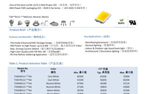
The 3020 series represents a high-performance mid-power LED solution designed for general lighting applications. Utilizing a Thermally Enhanced Epoxy Molding Compound (EMC) package, this LED offers an excellent balance of luminous efficacy, reliability, and cost-effectiveness. The primary positioning of this product is within the retrofit and general illumination markets, targeting applications where both high light output per dollar and good color quality are paramount. Its core advantages include one of the best lumen-per-watt and lumen-per-dollar ratios in its class, a robust package capable of handling up to 0.8W, and a high color rendering index (CRI) of 80 or above. The target market encompasses a wide range of lighting solutions, from direct replacements for traditional lamps to architectural and decorative lighting.
In-Depth Technical Parameter Analysis
Photometric and Optical Characteristics
The electro-optical performance is specified at a standard test condition of 150mA forward current (IF) and an ambient temperature (Ta) of 25°C. The product family offers Correlated Color Temperatures (CCT) ranging from Warm White (2580K-3220K) to Cool White (5310K-7040K). For a typical Neutral White variant (e.g., T3450811C), the luminous flux can reach up to 68 lumens. A key feature is the guaranteed minimum Color Rendering Index (CRI or Ra) of 80 across all bins, ensuring good color fidelity. The spatial light distribution is characterized by a wide viewing angle (2θ1/2) of 110 degrees, providing uniform illumination. It is important to note the specified measurement tolerances: ±7% for luminous flux and ±2 for CRI.
Electrical and Thermal Parameters
The electrical characteristics define the operational boundaries. The typical forward voltage (VF) is 3.4V at 150mA, with a tolerance of ±0.1V. The absolute maximum ratings are critical for reliable design: the maximum continuous forward current (IF) is 240mA, with a pulsed current (IFP) of 300mA allowed under specific conditions (pulse width ≤ 100µs, duty cycle ≤ 1/10). The maximum power dissipation (PD) is 816mW. Thermal management is facilitated by a low thermal resistance (Rth j-sp) of 21°C/W (junction to solder point), which is essential for maintaining performance and longevity. The maximum allowable junction temperature (Tj) is 115°C.
Binning System Explanation
Wavelength / Color Temperature Binning
The LED color consistency is controlled through a precise binning structure based on the CIE 1931 chromaticity diagram. The system uses elliptical bins defined by a center point (x, y coordinates), semi-major axis (a), semi-minor axis (b), and rotation angle (Φ). For example, the 40M5 bin for Neutral White has a center at (0.3825, 0.3798). The binning for color temperatures between 2600K and 7000K follows the Energy Star standard, ensuring tight color consistency for applications requiring uniform white light. The measurement uncertainty for color coordinates is ±0.007.
Luminous Flux Binning
Luminous output is also categorized into bins to guarantee performance. Each color bin (e.g., 27M5, 30M5) is further divided into luminous flux ranks identified by codes like E7, E8, F1, etc. For instance, within the 30M5 color bin, an LED with a flux code F1 will have a luminous flux between 66 and 70 lumens at 150mA. This allows designers to select LEDs with predictable light output for their specific application needs.
Forward Voltage Binning
To aid in circuit design and current matching, especially in multi-LED arrays, the forward voltage is sorted into three ranks: Code 1 (2.8V - 3.0V), Code 2 (3.0V - 3.2V), and Code 3 (3.2V - 3.4V). This helps in predicting power supply requirements and managing thermal loads more effectively.
Performance Curve Analysis
Current-Voltage (I-V) and Current-Luminous Flux (I-Φ) Characteristics
Figure 3 illustrates the relationship between forward current and relative luminous flux. The output is nearly linear up to the recommended operating current, showing good efficiency. Figure 4 shows the forward voltage versus current curve, which is essential for driver design. The positive temperature coefficient of the voltage is evident, meaning VF decreases as temperature increases, a typical behavior for LEDs.
Temperature Dependency
The performance variation with temperature is a critical design factor. Figure 6 shows that relative luminous flux decreases as ambient temperature (Ta) increases, highlighting the importance of thermal management to maintain light output. Figure 7 demonstrates the decrease in forward voltage with rising temperature. Figure 8 provides a derating curve for the maximum allowable forward current based on ambient temperature, which is crucial for ensuring reliability under different operating conditions.
Spectral and Angular Distribution
Figure 1 provides the relative spectral power distribution, which defines the color quality and CCT. Figure 2 depicts the viewing angle distribution (spatial radiation pattern), confirming the wide 110-degree beam angle for even illumination.
Color Shift with Temperature
Figure 5 plots the shift in CIE x, y chromaticity coordinates with increasing ambient temperature (from 25°C to 85°C). This information is vital for applications where color stability over temperature is a requirement.
Soldering and Assembly Guidelines
The LED is compatible with lead-free reflow soldering processes. The absolute maximum rating for soldering temperature is 230°C or 260°C for a maximum duration of 10 seconds. It is imperative to follow the recommended reflow profile to prevent thermal damage to the EMC package and the internal die. The operating temperature range is from -40°C to +85°C, and the storage temperature range is identical. Care must be taken not to exceed the absolute maximum ratings during operation, as this can cause irreversible damage to the LED.
Application Recommendations
Typical Application Scenarios
The datasheet identifies several key applications: retrofitting traditional lamps (like incandescent or CFL), general indoor and outdoor lighting, backlighting for indoor/outdoor sign boards, and architectural/decorative lighting. The combination of high efficacy, good CRI, and a wide beam angle makes it suitable for these diverse uses.
Design Considerations
Designers must pay close attention to thermal management. Utilizing the provided thermal resistance value (21°C/W), proper heatsinking must be calculated to keep the junction temperature below 115°C under worst-case operating conditions. The derating curve for current (Fig. 8) must be followed for high ambient temperature applications. For constant light output, a constant current driver is recommended over a constant voltage driver. When designing multi-LED arrays, consider using LEDs from the same voltage and flux bins to ensure uniform brightness and current sharing.
Technical Comparison and Differentiation
Compared to traditional mid-power LEDs in plastic packages, the EMC package offers significantly better thermal performance, allowing for higher drive currents and power dissipation (up to 0.8W) while maintaining reliability. This translates to higher lumen output from a similarly sized package. The guaranteed CRI of 80+ provides a competitive edge in applications where color quality is important, compared to standard offerings with lower CRI. The wide 110-degree viewing angle is advantageous for applications requiring broad, even illumination without secondary optics.
Frequently Asked Questions (Based on Technical Parameters)
Q: What is the maximum power I can drive this LED at?
A: The absolute maximum power dissipation is 816mW. However, the recommended operating condition is based on 0.5W nominal. Operating at higher power requires excellent thermal management to stay within the junction temperature limit.
Q: How do I interpret the luminous flux bins (E7, F1, etc.)?
A: These codes represent ranges of luminous output at 150mA. You must cross-reference the code with the specific color bin table (Table 6) to find the minimum and maximum lumen values for that group.
Q: Can I use a constant voltage source to drive this LED?
A: It is not recommended. LEDs are current-driven devices. A small change in forward voltage can cause a large change in current, potentially exceeding maximum ratings. Always use a constant current driver or a circuit that actively limits current.
Q: What is the impact of the ±7% flux tolerance?
A: This means the actual measured luminous flux of a production LED can vary by ±7% from the typical value listed in the datasheet. The binning system helps control this variation by grouping LEDs into tighter flux ranges.
Practical Use Case
Scenario: Designing a 10W LED Bulb Retrofit
A designer aims to create an A19 bulb replacement using this 3020 LED. Targeting 800 lumens, they might use 16 LEDs driven at approximately 140mA each (slightly below the test current for better efficacy and thermal headroom). They would select LEDs from the same color bin (e.g., 40M5 for 4000K Neutral White) and a consistent flux bin (e.g., F1) to ensure color and brightness uniformity. The total forward voltage for 16 LEDs in series would be roughly 16 * 3.4V = 54.4V, dictating the driver specifications. A properly designed aluminum PCB with thermal vias would be necessary to sink the heat from the 10W total dissipation, keeping individual junction temperatures well below the 115°C maximum.
Operating Principle Introduction
Light Emitting Diodes (LEDs) are semiconductor devices that emit light through electroluminescence. When a forward voltage is applied across the p-n junction, electrons and holes recombine in the active region, releasing energy in the form of photons. The wavelength (color) of the emitted light is determined by the bandgap energy of the semiconductor materials used. White light in this LED is typically generated by using a blue-emitting semiconductor chip coated with a phosphor layer. Part of the blue light is converted by the phosphor to longer wavelengths (yellow, red), and the mixture of blue and phosphor-converted light appears white to the human eye. The EMC package serves to protect the semiconductor die and wire bonds, provide a primary optical lens, and most importantly, offer a path for efficient heat conduction away from the junction.
Technology Trends
The mid-power LED segment continues to evolve towards higher efficacy (lumens per watt) and higher reliability at lower cost. Key trends include the adoption of more robust package materials like EMC and ceramic to enable higher operating temperatures and currents, leading to higher lumen density. There is a continuous push for improved phosphor technology to achieve higher Color Rendering Index (CRI) values and more consistent color quality across batches. Furthermore, integration of multiple die within a single package (COB - Chip-on-Board or multi-die mid-power) is a trend to simplify assembly and reduce system costs for high-lumen applications. The drive for smart lighting is also influencing LED design, with a focus on compatibility with dimming protocols and tunable white systems.
LED Specification Terminology
Complete explanation of LED technical terms
Photoelectric Performance
| Term | Unit/Representation | Simple Explanation | Why Important |
|---|---|---|---|
| Luminous Efficacy | lm/W (lumens per watt) | Light output per watt of electricity, higher means more energy efficient. | Directly determines energy efficiency grade and electricity cost. |
| Luminous Flux | lm (lumens) | Total light emitted by source, commonly called "brightness". | Determines if the light is bright enough. |
| Viewing Angle | ° (degrees), e.g., 120° | Angle where light intensity drops to half, determines beam width. | Affects illumination range and uniformity. |
| CCT (Color Temperature) | K (Kelvin), e.g., 2700K/6500K | Warmth/coolness of light, lower values yellowish/warm, higher whitish/cool. | Determines lighting atmosphere and suitable scenarios. |
| CRI / Ra | Unitless, 0–100 | Ability to render object colors accurately, Ra≥80 is good. | Affects color authenticity, used in high-demand places like malls, museums. |
| SDCM | MacAdam ellipse steps, e.g., "5-step" | Color consistency metric, smaller steps mean more consistent color. | Ensures uniform color across same batch of LEDs. |
| Dominant Wavelength | nm (nanometers), e.g., 620nm (red) | Wavelength corresponding to color of colored LEDs. | Determines hue of red, yellow, green monochrome LEDs. |
| Spectral Distribution | Wavelength vs intensity curve | Shows intensity distribution across wavelengths. | Affects color rendering and quality. |
Electrical Parameters
| Term | Symbol | Simple Explanation | Design Considerations |
|---|---|---|---|
| Forward Voltage | Vf | Minimum voltage to turn on LED, like "starting threshold". | Driver voltage must be ≥Vf, voltages add up for series LEDs. |
| Forward Current | If | Current value for normal LED operation. | Usually constant current drive, current determines brightness & lifespan. |
| Max Pulse Current | Ifp | Peak current tolerable for short periods, used for dimming or flashing. | Pulse width & duty cycle must be strictly controlled to avoid damage. |
| Reverse Voltage | Vr | Max reverse voltage LED can withstand, beyond may cause breakdown. | Circuit must prevent reverse connection or voltage spikes. |
| Thermal Resistance | Rth (°C/W) | Resistance to heat transfer from chip to solder, lower is better. | High thermal resistance requires stronger heat dissipation. |
| ESD Immunity | V (HBM), e.g., 1000V | Ability to withstand electrostatic discharge, higher means less vulnerable. | Anti-static measures needed in production, especially for sensitive LEDs. |
Thermal Management & Reliability
| Term | Key Metric | Simple Explanation | Impact |
|---|---|---|---|
| Junction Temperature | Tj (°C) | Actual operating temperature inside LED chip. | Every 10°C reduction may double lifespan; too high causes light decay, color shift. |
| Lumen Depreciation | L70 / L80 (hours) | Time for brightness to drop to 70% or 80% of initial. | Directly defines LED "service life". |
| Lumen Maintenance | % (e.g., 70%) | Percentage of brightness retained after time. | Indicates brightness retention over long-term use. |
| Color Shift | Δu′v′ or MacAdam ellipse | Degree of color change during use. | Affects color consistency in lighting scenes. |
| Thermal Aging | Material degradation | Deterioration due to long-term high temperature. | May cause brightness drop, color change, or open-circuit failure. |
Packaging & Materials
| Term | Common Types | Simple Explanation | Features & Applications |
|---|---|---|---|
| Package Type | EMC, PPA, Ceramic | Housing material protecting chip, providing optical/thermal interface. | EMC: good heat resistance, low cost; Ceramic: better heat dissipation, longer life. |
| Chip Structure | Front, Flip Chip | Chip electrode arrangement. | Flip chip: better heat dissipation, higher efficacy, for high-power. |
| Phosphor Coating | YAG, Silicate, Nitride | Covers blue chip, converts some to yellow/red, mixes to white. | Different phosphors affect efficacy, CCT, and CRI. |
| Lens/Optics | Flat, Microlens, TIR | Optical structure on surface controlling light distribution. | Determines viewing angle and light distribution curve. |
Quality Control & Binning
| Term | Binning Content | Simple Explanation | Purpose |
|---|---|---|---|
| Luminous Flux Bin | Code e.g., 2G, 2H | Grouped by brightness, each group has min/max lumen values. | Ensures uniform brightness in same batch. |
| Voltage Bin | Code e.g., 6W, 6X | Grouped by forward voltage range. | Facilitates driver matching, improves system efficiency. |
| Color Bin | 5-step MacAdam ellipse | Grouped by color coordinates, ensuring tight range. | Guarantees color consistency, avoids uneven color within fixture. |
| CCT Bin | 2700K, 3000K etc. | Grouped by CCT, each has corresponding coordinate range. | Meets different scene CCT requirements. |
Testing & Certification
| Term | Standard/Test | Simple Explanation | Significance |
|---|---|---|---|
| LM-80 | Lumen maintenance test | Long-term lighting at constant temperature, recording brightness decay. | Used to estimate LED life (with TM-21). |
| TM-21 | Life estimation standard | Estimates life under actual conditions based on LM-80 data. | Provides scientific life prediction. |
| IESNA | Illuminating Engineering Society | Covers optical, electrical, thermal test methods. | Industry-recognized test basis. |
| RoHS / REACH | Environmental certification | Ensures no harmful substances (lead, mercury). | Market access requirement internationally. |
| ENERGY STAR / DLC | Energy efficiency certification | Energy efficiency and performance certification for lighting. | Used in government procurement, subsidy programs, enhances competitiveness. |