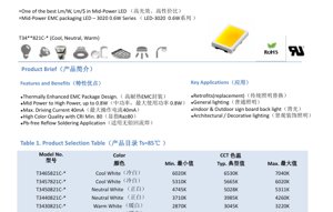
1. Product Overview
The 3020 series represents a family of mid-power LEDs utilizing a Thermally Enhanced Epoxy Molding Compound (EMC) package. This design is engineered to deliver an optimal balance between luminous efficacy (lumens per watt) and cost-effectiveness (lumens per dollar), making it a compelling choice for a wide range of general lighting applications. The series is characterized by its compact 3.0mm x 2.0mm footprint and is rated for a typical power dissipation of 0.6W, with a maximum allowable power of 0.8W under specified conditions.
1.1 Core Advantages and Target Market
The primary benefits of this LED series stem from its EMC packaging and design optimizations. The EMC material offers superior thermal resistance and long-term reliability compared to traditional plastics, enabling stable performance at higher operating temperatures. Key features include a maximum forward current of 40mA, a minimum Color Rendering Index (CRI) of 80 for high color quality, and compatibility with lead-free reflow soldering processes. These attributes make the series ideal for retrofit lamps, general indoor and outdoor lighting, backlighting for signage, and architectural or decorative lighting fixtures where a combination of efficiency, reliability, and color quality is paramount.
2. In-Depth Technical Parameter Analysis
This section provides a detailed, objective interpretation of the key performance parameters specified in the datasheet. Understanding these values is critical for proper circuit design and thermal management.
2.1 Electro-Optical Characteristics
The electro-optical performance is measured under standard test conditions of IF = 30mA, Ta = 25°C, and 60% relative humidity. The luminous flux output is provided for two critical temperatures: the ambient temperature (Ta=25°C) and the solder point temperature (Ts=85°C). The latter is a more realistic indicator of performance in an actual application where the LED is mounted on a board. For example, a typical cool white bin (65R6) delivers 72 lumens at Ta=25°C but 62 lumens at Ts=85°C, highlighting the importance of thermal design. The datasheet notes a ±7% tolerance on luminous flux measurements and a ±2 tolerance on CRI (Ra) measurements.
2.2 Electrical and Thermal Parameters
The forward voltage (VF) has a typical value of 19V at 30mA, with a specified tolerance of ±0.3V. The viewing angle (2Θ1/2) is a wide 120 degrees, defined as the off-axis angle where luminous intensity drops to half of its peak value. A critical thermal parameter is the junction-to-solder point thermal resistance (Rth j-sp), specified at a typical 22 °C/W. This value quantifies how effectively heat flows from the semiconductor junction to the solder point; a lower value indicates better heat dissipation. The electrostatic discharge (ESD) withstand level is 1000V (Human Body Model), which is a standard level for mid-power LEDs.
2.3 Absolute Maximum Ratings
These ratings define the stress limits beyond which permanent damage may occur. They must not be exceeded under any operating conditions. Key limits include: a continuous forward current (IF) of 40mA, a pulse forward current (IFP) of 60mA (for pulses ≤ 100µs, duty cycle ≤ 1/10), a maximum power dissipation (PD) of 840mW, and a maximum junction temperature (Tj) of 125°C. The operating and storage temperature range is -40°C to +105°C. The soldering temperature profile allows for a peak of 230°C or 260°C for a maximum of 10 seconds.
3. Binning System Explanation
To ensure color and brightness consistency in production, LEDs are sorted into bins. This series employs a comprehensive binning system based on Energy Star guidelines for the 2600K to 7000K range.
3.1 Correlated Color Temperature (CCT) and Chromaticity Binning
The product selection table lists six primary CCT groups, from Warm White (2725K, 3045K) to Cool White (6530K). Each CCT group has a corresponding color bin code (e.g., 27R5, 65R6). Table 5 and Figure 9 detail the chromaticity bin structure on the CIE 1931 diagram. Each bin is defined by an elliptical area with a specific center coordinate (x, y) at both 25°C and 85°C, along with major/minor axis radii (a, b) and an angle (Φ). The measurement uncertainty for color coordinates is ±0.007.
3.2 Luminous Flux Binning
Within each chromaticity bin, LEDs are further sorted by their luminous flux output at 30mA. Table 6 defines the flux ranks. For instance, within the 65R6 color bin, LEDs are available in flux codes F1 (66-70 lm min), F2 (70-74 lm min), and F3 (74-78 lm min), all measured at Ta=25°C. This two-dimensional binning (color + flux) allows designers to select LEDs that meet precise application requirements for both color point and brightness.
4. Performance Curve Analysis
The datasheet includes several graphs that illustrate the LED's behavior under varying conditions, which are essential for predictive modeling and robust design.
4.1 IV Characteristics and Relative Luminous Flux
Figure 4 shows the relationship between forward voltage (VF) and forward current (IF). The curve is relatively linear in the operating range, with VF increasing with current. Figure 3 plots relative luminous flux against IF. The flux increases sub-linearly with current; driving the LED above the recommended 30mA will yield diminishing returns in light output while generating significantly more heat, potentially reducing efficacy and lifetime.
4.2 Temperature Dependence
Figures 6 and 7 are critical for thermal analysis. Figure 6 shows the relative luminous flux decreasing linearly as the solder point temperature (Ts) increases. At 125°C, the output is roughly 20% of its value at 25°C. Figure 7 shows that VF also decreases with increasing temperature, a typical characteristic of semiconductor diodes. Figure 5 illustrates the shift in chromaticity coordinates (CIE x, y) with temperature, which is important for color-critical applications.
3.3 Spectral Distribution and Viewing Angle
Figure 1 provides a typical spectral power distribution curve, showing the relative intensity across wavelengths. The shape of this curve determines the CCT and CRI. Figure 2 depicts the spatial radiation pattern (viewing angle distribution), confirming the Lambertian-like emission profile with the specified 120-degree viewing angle.
4.4 Ambient Temperature Derating
Figure 8 is a derating curve for maximum allowable forward current based on ambient temperature (Ta) and the system's thermal resistance (Rj-a). For example, with a system Rj-a of 45°C/W, the maximum current must be reduced from 40mA at Ta=89°C to approximately 22mA at Ta=105°C to prevent the junction temperature from exceeding its 125°C limit. This graph is essential for determining safe operating currents in high-temperature environments.
5. Application Guidelines and Design Considerations
5.1 Typical Application Scenarios
Due to its balance of efficacy, cost, and reliability, this LED series is well-suited for:
- Retrofit Lamps: Direct replacement for incandescent, halogen, or CFL bulbs in bulbs, tubes, and downlights.
- General Lighting: Primary light source in residential, commercial, and industrial fixtures.
- Signage Backlighting: Providing uniform illumination for indoor and outdoor signs.
- Architectural Lighting: Facade lighting, cove lighting, and other decorative applications where color quality is important.
5.2 Critical Design Considerations
Thermal Management: This is the single most important factor for performance and longevity. The low Rth j-sp of 22°C/W is only effective if the PCB and heatsink provide a low thermal path to ambient. Use of metal-core PCBs (MCPCBs) or boards with adequate thermal vias is strongly recommended. Always refer to the derating curve (Fig. 8) to set the drive current.
Current Drive: A constant current driver is mandatory for stable light output and color. The recommended operating current is 30mA, though it can be driven up to 40mA if thermal conditions are excellent. Exceeding 40mA risks immediate damage.
Optics: The 120-degree viewing angle is suitable for many general lighting applications. For more focused beams, secondary optics (lenses) will be required.
ESD Protection: While rated for 1000V HBM, standard ESD handling precautions should be observed during assembly and handling.
6. Comparative Analysis and Technical Differentiation
Within the mid-power LED segment, the key differentiators of this 3020 EMC series are:
1. High-Temperature Capability: The EMC package allows for sustained operation at higher solder point temperatures (Ts=85°C data provided) compared to standard PPA or PCT plastics, which can yellow and degrade.
2. Power Density: With a capability up to 0.8W in a 3.0x2.0mm package, it offers higher power density than many traditional 3528 or 2835 mid-power LEDs, potentially reducing the number of LEDs needed for a given lumen output.
3. Voltage Characteristic: The typical 19V forward voltage at 30mA is notable. Designers must ensure the LED driver is configured for this higher voltage range compared to more common 3V or 6V mid-power LEDs.
4. Comprehensive Binning: The adherence to Energy Star binning and the provision of both color and flux bins offer predictability and consistency for quality lighting products.
7. Frequently Asked Questions (Based on Technical Parameters)
Q: Why is the luminous flux lower at Ts=85°C than at Ta=25°C?
A: Ta is the air temperature around the LED. Ts is the temperature at the solder point, which is much closer to the actual junction temperature during operation. As temperature rises, semiconductor efficiency drops, reducing light output. The Ts=85°C data is a more realistic performance metric for design.
Q: Can I drive this LED at 40mA continuously?
A: The Absolute Maximum Rating is 40mA, but this is a stress limit. The recommended operating condition is 30mA. Operating at 40mA is possible only if the thermal management is exceptional (very low system Rj-a) and the ambient temperature is low, as per the derating curve in Fig. 8. Doing so will reduce efficacy and may impact long-term reliability.
Q: How do I interpret the bin code, for example, '65R6'?
A: The code defines the chromaticity bin. The first two digits (65) relate to the CCT (6500K range). The letter (R) and the following digit (6) define the specific ellipse on the CIE diagram where the LED's color coordinates fall, ensuring tight color consistency.
Q: What is the significance of the 22 °C/W thermal resistance?
A: This value (Rth j-sp) indicates that for every watt of power dissipated in the LED junction, the temperature difference between the junction and the solder point will increase by 22°C. A lower value is better. The total system thermal resistance (junction-to-ambient, Rj-a) includes this plus the resistance of the PCB, thermal interface, and heatsink.
8. Design and Usage Case Study
Scenario: Designing a 1200 Lumen LED Tube Light.
Goal: Replace a fluorescent T8 tube with an LED equivalent.
Design Process:
1. Lumen Target: 1200 lumens.
2. LED Selection: Choose the 65R6-F2 bin (Typical 72 lm at 30mA, Ta=25°C). Accounting for thermal derating (estimate ~15% loss at operating temperature), assume 61 lm per LED.
3. Quantity Calculation: 1200 lm / 61 lm per LED ≈ 20 LEDs.
4. Electrical Design: 20 LEDs in series would require a drive voltage of 20 * 19V = 380V, which is high. A more practical approach is to use two strings of 10 LEDs in series (190V per string) connected in parallel, driven by a constant current driver set to 60mA total (30mA per string).
5. Thermal Design: Total power: 20 LEDs * 19V * 0.03A = 11.4W. Using an aluminum PCB as a heatsink, the designer must calculate if the system Rj-a is low enough to keep the junction below 125°C in the enclosed tube environment, using the derating curve as a guide.
This case highlights the interplay between electrical configuration, thermal management, and photometric targets.
9. Technical Principles and Trends
9.1 Operating Principle
This LED operates on the principle of electroluminescence in a semiconductor. When a forward voltage is applied across the p-n junction, electrons and holes recombine, releasing energy in the form of photons. The specific materials (phosphors) used in the package convert a portion of the primary blue light from the chip into longer wavelengths, resulting in the desired white light with a specific CCT and CRI. The EMC package serves to protect the chip and wire bonds, provide a primary lens, and most importantly, offer a thermally conductive path to dissipate heat.
9.2 Industry Trends
The mid-power LED market continues to evolve towards higher efficacy (lm/W) and improved reliability at lower cost. The use of EMC packages, as seen in this series, is a significant trend replacing traditional plastics due to superior resistance to heat and humidity, enabling longer lifetimes and higher drive currents. Furthermore, there is a continuous push for tighter color and flux binning to meet the demands of high-quality lighting. The integration of these components into modules and light engines is also a growing trend, simplifying design for lighting manufacturers. The data provided in this datasheet reflects the current industry standard for characterizing and specifying performance under realistic thermal conditions.
LED Specification Terminology
Complete explanation of LED technical terms
Photoelectric Performance
| Term | Unit/Representation | Simple Explanation | Why Important |
|---|---|---|---|
| Luminous Efficacy | lm/W (lumens per watt) | Light output per watt of electricity, higher means more energy efficient. | Directly determines energy efficiency grade and electricity cost. |
| Luminous Flux | lm (lumens) | Total light emitted by source, commonly called "brightness". | Determines if the light is bright enough. |
| Viewing Angle | ° (degrees), e.g., 120° | Angle where light intensity drops to half, determines beam width. | Affects illumination range and uniformity. |
| CCT (Color Temperature) | K (Kelvin), e.g., 2700K/6500K | Warmth/coolness of light, lower values yellowish/warm, higher whitish/cool. | Determines lighting atmosphere and suitable scenarios. |
| CRI / Ra | Unitless, 0–100 | Ability to render object colors accurately, Ra≥80 is good. | Affects color authenticity, used in high-demand places like malls, museums. |
| SDCM | MacAdam ellipse steps, e.g., "5-step" | Color consistency metric, smaller steps mean more consistent color. | Ensures uniform color across same batch of LEDs. |
| Dominant Wavelength | nm (nanometers), e.g., 620nm (red) | Wavelength corresponding to color of colored LEDs. | Determines hue of red, yellow, green monochrome LEDs. |
| Spectral Distribution | Wavelength vs intensity curve | Shows intensity distribution across wavelengths. | Affects color rendering and quality. |
Electrical Parameters
| Term | Symbol | Simple Explanation | Design Considerations |
|---|---|---|---|
| Forward Voltage | Vf | Minimum voltage to turn on LED, like "starting threshold". | Driver voltage must be ≥Vf, voltages add up for series LEDs. |
| Forward Current | If | Current value for normal LED operation. | Usually constant current drive, current determines brightness & lifespan. |
| Max Pulse Current | Ifp | Peak current tolerable for short periods, used for dimming or flashing. | Pulse width & duty cycle must be strictly controlled to avoid damage. |
| Reverse Voltage | Vr | Max reverse voltage LED can withstand, beyond may cause breakdown. | Circuit must prevent reverse connection or voltage spikes. |
| Thermal Resistance | Rth (°C/W) | Resistance to heat transfer from chip to solder, lower is better. | High thermal resistance requires stronger heat dissipation. |
| ESD Immunity | V (HBM), e.g., 1000V | Ability to withstand electrostatic discharge, higher means less vulnerable. | Anti-static measures needed in production, especially for sensitive LEDs. |
Thermal Management & Reliability
| Term | Key Metric | Simple Explanation | Impact |
|---|---|---|---|
| Junction Temperature | Tj (°C) | Actual operating temperature inside LED chip. | Every 10°C reduction may double lifespan; too high causes light decay, color shift. |
| Lumen Depreciation | L70 / L80 (hours) | Time for brightness to drop to 70% or 80% of initial. | Directly defines LED "service life". |
| Lumen Maintenance | % (e.g., 70%) | Percentage of brightness retained after time. | Indicates brightness retention over long-term use. |
| Color Shift | Δu′v′ or MacAdam ellipse | Degree of color change during use. | Affects color consistency in lighting scenes. |
| Thermal Aging | Material degradation | Deterioration due to long-term high temperature. | May cause brightness drop, color change, or open-circuit failure. |
Packaging & Materials
| Term | Common Types | Simple Explanation | Features & Applications |
|---|---|---|---|
| Package Type | EMC, PPA, Ceramic | Housing material protecting chip, providing optical/thermal interface. | EMC: good heat resistance, low cost; Ceramic: better heat dissipation, longer life. |
| Chip Structure | Front, Flip Chip | Chip electrode arrangement. | Flip chip: better heat dissipation, higher efficacy, for high-power. |
| Phosphor Coating | YAG, Silicate, Nitride | Covers blue chip, converts some to yellow/red, mixes to white. | Different phosphors affect efficacy, CCT, and CRI. |
| Lens/Optics | Flat, Microlens, TIR | Optical structure on surface controlling light distribution. | Determines viewing angle and light distribution curve. |
Quality Control & Binning
| Term | Binning Content | Simple Explanation | Purpose |
|---|---|---|---|
| Luminous Flux Bin | Code e.g., 2G, 2H | Grouped by brightness, each group has min/max lumen values. | Ensures uniform brightness in same batch. |
| Voltage Bin | Code e.g., 6W, 6X | Grouped by forward voltage range. | Facilitates driver matching, improves system efficiency. |
| Color Bin | 5-step MacAdam ellipse | Grouped by color coordinates, ensuring tight range. | Guarantees color consistency, avoids uneven color within fixture. |
| CCT Bin | 2700K, 3000K etc. | Grouped by CCT, each has corresponding coordinate range. | Meets different scene CCT requirements. |
Testing & Certification
| Term | Standard/Test | Simple Explanation | Significance |
|---|---|---|---|
| LM-80 | Lumen maintenance test | Long-term lighting at constant temperature, recording brightness decay. | Used to estimate LED life (with TM-21). |
| TM-21 | Life estimation standard | Estimates life under actual conditions based on LM-80 data. | Provides scientific life prediction. |
| IESNA | Illuminating Engineering Society | Covers optical, electrical, thermal test methods. | Industry-recognized test basis. |
| RoHS / REACH | Environmental certification | Ensures no harmful substances (lead, mercury). | Market access requirement internationally. |
| ENERGY STAR / DLC | Energy efficiency certification | Energy efficiency and performance certification for lighting. | Used in government procurement, subsidy programs, enhances competitiveness. |