1. Product Overview
This document details the specifications for a series of mid-power LEDs utilizing a 3030 footprint and an Epoxy Molding Compound (EMC) package. Designed for high efficiency and cost-effectiveness, this series represents a robust solution for a wide range of general and decorative lighting applications. The EMC material provides superior thermal management compared to traditional plastics, enabling reliable operation at higher power levels.
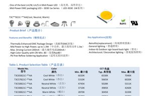
The core advantages of this product line include one of the best lumen-per-watt and lumen-per-dollar ratios in the mid-power segment. It is engineered to bridge the gap between mid-power and high-power applications, with a maximum power dissipation of 1.36W and a recommended maximum drive current of 200mA. The LEDs are available in a spectrum of correlated color temperatures (CCT) from warm white (2725K) to cool white (6530K), all with a minimum Color Rendering Index (CRI) of 80, ensuring good color quality for illuminated spaces.
1.1 Key Features and Benefits
- Thermally Enhanced EMC Package: The package design offers excellent heat dissipation, improving longevity and maintaining light output stability.
- High Power Capability: Suitable for applications up to 1.3W, blurring the line between mid-power and high-power LEDs.
- High Drive Current: Supports a maximum continuous forward current (IF) of 200mA, allowing for higher luminous flux output.
- High Color Quality: Minimum CRI of 80 across all CCT bins provides accurate and pleasing color rendition.
- Pb-free and Reflow Compatible: Designed for use with lead-free solder and standard surface-mount technology (SMT) reflow processes.
2. Technical Parameter Analysis
2.1 Electro-Optical Characteristics
The primary performance data is measured at a standard test condition of IF = 150mA and Ta = 25°C. The luminous flux output varies by color bin, with typical values ranging from approximately 119 lm to 131 lm. A wide viewing angle (2θ1/2) of 110 degrees ensures broad, even illumination. The forward voltage (VF) at 150mA has a typical value of 6.8V, with a tolerance of ±0.1V. It is crucial to note the provided measurement tolerances: ±7% for luminous flux and ±2 for CRI (Ra).
2.2 Electrical and Thermal Parameters
The absolute maximum ratings define the operational limits. The maximum continuous forward current is 200mA, with a pulsed forward current (IFP) of 300mA allowed under specific conditions (pulse width ≤ 100µs, duty cycle ≤ 1/10). The maximum power dissipation is 1360 mW. The junction-to-solder point thermal resistance (Rth j-sp) is 14 °C/W, a key parameter for thermal management design. The device can operate and be stored within a temperature range of -40°C to +85°C, with a maximum junction temperature (Tj) of 115°C.
2.3 Soldering Specifications
The LED is rated for reflow soldering. The peak soldering temperature should not exceed 230°C or 260°C, with the exposure time at peak temperature limited to 10 seconds. Adhering to these profiles is essential to prevent package damage or degradation of the internal components.
3. Binning System Explanation
To ensure color and brightness consistency in production, the LEDs are sorted into bins.
3.1 Color (CCT) Binning
The product uses an Energy Star compliant binning structure for CCTs between 2600K and 7000K. Six primary bins are defined (27M5, 30M5, 40M5, 50M5, 57M6, 65M6), each corresponding to a specific nominal CCT and a defined ellipse on the CIE 1931 chromaticity diagram. The center coordinates (x, y), ellipse radii (a, b), and angle (Φ) for each bin are precisely specified, with a color coordinate measurement uncertainty of ±0.007.
3.2 Luminous Flux Binning
Within each color bin, LEDs are further sorted by their luminous flux output at 150mA. Flux ranks are designated by codes (e.g., 2C, 2D, 2E, 2F, 2G), each representing a minimum and maximum flux range. For example, in the 27M5 color bin, code 2C covers 107-114 lm, 2D covers 114-122 lm, and 2E covers 122-130 lm. This allows designers to select components based on precise brightness requirements.
3.3 Forward Voltage Binning
While the detailed table for voltage binning is not fully extracted in the provided content, it is standard practice to group LEDs by their forward voltage (VF) at a specified current. This helps in designing more consistent driver circuits and managing power distribution in arrays.
4. Performance Curve Analysis
4.1 IV and Luminous Flux Characteristics
Figure 3 shows the relationship between forward current (IF) and relative luminous flux. The flux increases with current but exhibits a sub-linear trend at higher currents, likely due to increased thermal effects and efficiency droop. Figure 4 depicts the forward voltage (VF) versus forward current (IF), showing the typical diode characteristic curve.
4.2 Temperature Dependence
Figures 6 and 7 illustrate the impact of ambient temperature (Ta) on performance. As temperature rises, the relative luminous flux decreases (Figure 6), while the forward voltage also decreases (Figure 7). Figure 5 shows the shift in chromaticity coordinates (CIE x, y) with temperature, which is critical for applications requiring stable color points. Figure 8 is vital for design: it plots the maximum allowable forward current against ambient temperature for two different thermal resistance scenarios (Rj-a=35°C/W and 45°C/W). This graph defines the necessary derating of current as the ambient temperature increases to keep the junction temperature within safe limits.
4.3 Spectral and Angular Distribution
Figure 1 represents the relative spectral power distribution, which defines the color quality. Figure 2 shows the viewing angle distribution or radiation pattern, confirming the 110-degree beam angle.
5. Application Guidelines
5.1 Target Applications
- Retrofit Lamps: Direct replacement for traditional incandescent, halogen, or CFL bulbs in fixtures.
- General Lighting: Primary illumination for residential, commercial, and industrial spaces.
- Backlighting: For indoor and outdoor signage and display panels.
- Architectural/Decorative Lighting: Accent lighting, coves, and other aesthetic lighting installations.
5.2 Design Considerations
Thermal Management: The 14 °C/W thermal resistance necessitates an effective thermal path from the solder pads to a heatsink. Use Figure 8 to determine the appropriate drive current for your application's maximum expected ambient temperature. Exceeding the maximum ratings, especially Tj, will significantly reduce lifetime and reliability.
Electrical Design: Driver selection must account for the typical VF of 6.8V at 150mA. For constant current driving, ensure the driver's current output matches the desired operating point (e.g., 150mA or lower for better efficacy/lifetime). Consider the forward voltage binning to balance current in parallel strings.
Optical Design: The 110-degree viewing angle is suitable for broad, diffuse lighting. For more focused beams, secondary optics (lenses) will be required.
6. Technical Comparison and Trends
This 3030 EMC LED series positions itself in the competitive mid-power market. Its key differentiator is the use of EMC packaging, which typically offers better thermal conductivity and resistance to yellowing under high temperature/UV exposure compared to standard PPA or PCT plastics used in many mid-power LEDs. This allows it to be driven at higher currents (up to 200mA) while maintaining reliability, effectively offering a higher power density.
The trend in LED packaging continues toward materials and designs that improve thermal performance and allow for higher flux density from smaller packages. EMC and ceramic packages are at the forefront of this trend for both mid-power and high-power devices. The focus on high lm/$ and lm/W, as highlighted for this product, remains the primary driver for mass-market lighting adoption.
7. Frequently Asked Questions (FAQ)
Q: What is the actual power consumption at the typical operating point?
A: At the test condition of IF=150mA and VF=6.8V (typical), the electrical power is P = I*V = 0.15A * 6.8V = 1.02W.
Q: Can I drive this LED at 200mA continuously?
A: You can, but you must ensure the junction temperature (Tj) does not exceed 115°C. This requires excellent thermal management (low thermal resistance from junction to ambient). Refer to Figure 8 to see how the maximum allowable current decreases with rising ambient temperature.
Q: What does the \"M5\" or \"M6\" in the color bin code (e.g., 27M5) mean?
A> These codes refer to specific ellipses on the CIE chromaticity diagram defined by the ANSI C78.377 or Energy Star standards. The number (27, 30, etc.) relates to the nominal CCT (e.g., 2700K, 3000K). The letter and number (M5, M6) define the size and location of the color tolerance ellipse around that nominal point.
Q: How does the EMC package benefit my design compared to a plastic package?
A> The EMC material has higher thermal conductivity, allowing heat from the LED chip to be transferred to the board and heatsink more efficiently. This results in a lower operating junction temperature for the same drive current, which improves longevity, maintains higher light output, and allows for potential overdrive in well-cooled designs.
8. Design and Use Case Example
Scenario: Designing a 1200 lm LED Bulb Replacement (A19 Style)
A typical 60W incandescent equivalent LED bulb produces about 800 lumens. To create a brighter 100W equivalent (~1600 lm), a designer might use this 3030 LED.
Design Calculation: Targeting 1600 lm with LEDs having a typical flux of 124 lm (e.g., from 30M5 bin at 150mA), approximately 13 LEDs are needed (1600 / 124 ≈ 12.9). These would be arranged on a metal-core PCB (MCPCB) inside the bulb for heat dissipation. Driving all 13 in series would require a driver output voltage of ~13 * 6.8V = 88.4V, which is high. A more practical approach might be two parallel strings of 6-7 LEDs each, requiring a driver with a lower voltage but capable of providing twice the current. The total power would be roughly 13 * 1.02W = 13.3W, demonstrating high efficacy. The thermal design must ensure the base temperature of the bulb, which is the ambient for the LED board, stays within the limits defined by Figure 8 to allow 150mA operation.
LED Specification Terminology
Complete explanation of LED technical terms
Photoelectric Performance
| Term | Unit/Representation | Simple Explanation | Why Important |
|---|---|---|---|
| Luminous Efficacy | lm/W (lumens per watt) | Light output per watt of electricity, higher means more energy efficient. | Directly determines energy efficiency grade and electricity cost. |
| Luminous Flux | lm (lumens) | Total light emitted by source, commonly called "brightness". | Determines if the light is bright enough. |
| Viewing Angle | ° (degrees), e.g., 120° | Angle where light intensity drops to half, determines beam width. | Affects illumination range and uniformity. |
| CCT (Color Temperature) | K (Kelvin), e.g., 2700K/6500K | Warmth/coolness of light, lower values yellowish/warm, higher whitish/cool. | Determines lighting atmosphere and suitable scenarios. |
| CRI / Ra | Unitless, 0–100 | Ability to render object colors accurately, Ra≥80 is good. | Affects color authenticity, used in high-demand places like malls, museums. |
| SDCM | MacAdam ellipse steps, e.g., "5-step" | Color consistency metric, smaller steps mean more consistent color. | Ensures uniform color across same batch of LEDs. |
| Dominant Wavelength | nm (nanometers), e.g., 620nm (red) | Wavelength corresponding to color of colored LEDs. | Determines hue of red, yellow, green monochrome LEDs. |
| Spectral Distribution | Wavelength vs intensity curve | Shows intensity distribution across wavelengths. | Affects color rendering and quality. |
Electrical Parameters
| Term | Symbol | Simple Explanation | Design Considerations |
|---|---|---|---|
| Forward Voltage | Vf | Minimum voltage to turn on LED, like "starting threshold". | Driver voltage must be ≥Vf, voltages add up for series LEDs. |
| Forward Current | If | Current value for normal LED operation. | Usually constant current drive, current determines brightness & lifespan. |
| Max Pulse Current | Ifp | Peak current tolerable for short periods, used for dimming or flashing. | Pulse width & duty cycle must be strictly controlled to avoid damage. |
| Reverse Voltage | Vr | Max reverse voltage LED can withstand, beyond may cause breakdown. | Circuit must prevent reverse connection or voltage spikes. |
| Thermal Resistance | Rth (°C/W) | Resistance to heat transfer from chip to solder, lower is better. | High thermal resistance requires stronger heat dissipation. |
| ESD Immunity | V (HBM), e.g., 1000V | Ability to withstand electrostatic discharge, higher means less vulnerable. | Anti-static measures needed in production, especially for sensitive LEDs. |
Thermal Management & Reliability
| Term | Key Metric | Simple Explanation | Impact |
|---|---|---|---|
| Junction Temperature | Tj (°C) | Actual operating temperature inside LED chip. | Every 10°C reduction may double lifespan; too high causes light decay, color shift. |
| Lumen Depreciation | L70 / L80 (hours) | Time for brightness to drop to 70% or 80% of initial. | Directly defines LED "service life". |
| Lumen Maintenance | % (e.g., 70%) | Percentage of brightness retained after time. | Indicates brightness retention over long-term use. |
| Color Shift | Δu′v′ or MacAdam ellipse | Degree of color change during use. | Affects color consistency in lighting scenes. |
| Thermal Aging | Material degradation | Deterioration due to long-term high temperature. | May cause brightness drop, color change, or open-circuit failure. |
Packaging & Materials
| Term | Common Types | Simple Explanation | Features & Applications |
|---|---|---|---|
| Package Type | EMC, PPA, Ceramic | Housing material protecting chip, providing optical/thermal interface. | EMC: good heat resistance, low cost; Ceramic: better heat dissipation, longer life. |
| Chip Structure | Front, Flip Chip | Chip electrode arrangement. | Flip chip: better heat dissipation, higher efficacy, for high-power. |
| Phosphor Coating | YAG, Silicate, Nitride | Covers blue chip, converts some to yellow/red, mixes to white. | Different phosphors affect efficacy, CCT, and CRI. |
| Lens/Optics | Flat, Microlens, TIR | Optical structure on surface controlling light distribution. | Determines viewing angle and light distribution curve. |
Quality Control & Binning
| Term | Binning Content | Simple Explanation | Purpose |
|---|---|---|---|
| Luminous Flux Bin | Code e.g., 2G, 2H | Grouped by brightness, each group has min/max lumen values. | Ensures uniform brightness in same batch. |
| Voltage Bin | Code e.g., 6W, 6X | Grouped by forward voltage range. | Facilitates driver matching, improves system efficiency. |
| Color Bin | 5-step MacAdam ellipse | Grouped by color coordinates, ensuring tight range. | Guarantees color consistency, avoids uneven color within fixture. |
| CCT Bin | 2700K, 3000K etc. | Grouped by CCT, each has corresponding coordinate range. | Meets different scene CCT requirements. |
Testing & Certification
| Term | Standard/Test | Simple Explanation | Significance |
|---|---|---|---|
| LM-80 | Lumen maintenance test | Long-term lighting at constant temperature, recording brightness decay. | Used to estimate LED life (with TM-21). |
| TM-21 | Life estimation standard | Estimates life under actual conditions based on LM-80 data. | Provides scientific life prediction. |
| IESNA | Illuminating Engineering Society | Covers optical, electrical, thermal test methods. | Industry-recognized test basis. |
| RoHS / REACH | Environmental certification | Ensures no harmful substances (lead, mercury). | Market access requirement internationally. |
| ENERGY STAR / DLC | Energy efficiency certification | Energy efficiency and performance certification for lighting. | Used in government procurement, subsidy programs, enhances competitiveness. |