Table of Contents
- 1. Product Overview
- 1.1 Key Features and Benefits
- 1.2 Target Applications
- 2. Technical Parameter Analysis
- 2.1 Product Selection and Optical Characteristics
- 2.2 Electro-Optical and Electrical Parameters
- 2.3 Absolute Maximum Ratings
- 3. Performance Characteristics and Curves
- 3.1 Spectral and Angular Distribution
- 3.2 Forward Current Characteristics
- 3.3 Temperature Dependence
- 3.4 Derating and Maximum Current vs. Temperature
- 4. Color Bin Structure and Control
- 5. Application Guidelines and Design Considerations
- 5.1 Thermal Management
- 5.2 Electrical Drive
- 5.3 Soldering and Handling
- 5.4 Optical Design
- 6. Comparison and Positioning
- 7. Frequently Asked Questions (Based on Technical Parameters)
- 8. Practical Design Case Example
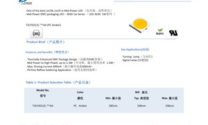
1. Product Overview
This document details the specifications for a 3030 mid-power LED in an amber color. The device utilizes a Thermally Enhanced Epoxy Molding Compound (EMC) package, designed to offer a balance of performance and cost-effectiveness. It is positioned as a solution offering excellent lumens per watt (lm/W) and lumens per dollar (lm/$) within the mid-power segment. The series is capable of handling power levels from mid-power up to 1.3W, making it suitable for applications requiring robust performance.
1.1 Key Features and Benefits
- Thermally Enhanced EMC Package Design: The EMC material provides improved thermal management compared to traditional plastics, leading to better reliability and lumen maintenance.
- High Power Capability: Capable of operating up to 1.3W, bridging the gap between standard mid-power and high-power LEDs.
- High Drive Current: Supports a maximum forward current of 400mA, allowing for higher light output when required.
- Pb-free Reflow Soldering: Compatible with standard lead-free reflow soldering processes, facilitating modern manufacturing.
1.2 Target Applications
The primary applications for this LED include automotive and signaling uses, such as turning indicator lamps and various signal lamps where amber light is specified.
2. Technical Parameter Analysis
2.1 Product Selection and Optical Characteristics
The specific model covered is the T3CYE012C-**AA, a Phosphor-Converted (PC) Amber LED. Its dominant wavelength (WD) ranges from a minimum of 585nm, typical of 590nm, to a maximum of 596nm. Under standard test conditions (Forward Current IF=350mA, Ambient Temperature Ta=25°C), the typical luminous flux is 118 lumens, with a minimum specified value of 107 lumens. The tolerance for luminous flux measurement is ±7%.
2.2 Electro-Optical and Electrical Parameters
Detailed electrical and optical parameters are defined under the same standard test conditions (IF=350mA, Ta=25°C, RH60%).
- Forward Voltage (VF): Typical value is 3.1V, with a range from 3.0V (Min) to 3.3V (Max).
- Reverse Current (IR): Maximum of 10 µA at a reverse voltage (VR) of 5V.
- Viewing Angle (2θ1/2): The half-intensity angle is typically 120 degrees.
- Thermal Resistance (Rth j-sp): The junction-to-solder point thermal resistance is typically 14 °C/W.
- Electrostatic Discharge (ESD): Withstands up to 8000V (Human Body Model), indicating good handling robustness.
2.3 Absolute Maximum Ratings
These ratings define the limits beyond which permanent damage may occur. Operation should be maintained within these limits.
- Forward Current (IF): 400 mA (Continuous)
- Pulse Forward Current (IFP): 500 mA (Pulse width ≤100µs, Duty cycle ≤1/10)
- Power Dissipation (PD): 1360 mW
- Reverse Voltage (VR): 5 V
- Operating Temperature (Topr): -40°C to +105°C
- Storage Temperature (Tstg): -40°C to +85°C
- Junction Temperature (Tj): 125°C
- Soldering Temperature (Tsld): 260°C for 10 seconds (or 230°C).
Important Note: Exceeding these absolute maximum ratings, even momentarily, may degrade device performance and reliability. Particular care must be taken to ensure the actual power dissipation does not exceed the rated value under operating conditions.
3. Performance Characteristics and Curves
3.1 Spectral and Angular Distribution
The LED emits in the amber spectrum, centered around 590nm. The viewing angle distribution chart shows a typical Lambertian or near-Lambertian pattern with a 120-degree half-angle, providing wide illumination.
3.2 Forward Current Characteristics
The relationship between forward current (IF) and relative luminous flux is non-linear. The flux increases with current but will eventually saturate and decrease due to thermal effects at higher currents. The graph shows performance at Ta=25°C. The forward voltage (VF) vs. forward current (IF) curve demonstrates the diode's characteristic, with VF increasing logarithmically with current.
3.3 Temperature Dependence
The performance of LEDs is significantly affected by temperature.
- Luminous Flux vs. Temperature: The relative luminous flux decreases as the ambient temperature (Ta) increases. This is a critical factor for system thermal design.
- Forward Voltage vs. Temperature: The forward voltage typically decreases with increasing junction temperature, which can be used for temperature monitoring in some applications.
- Color Shift vs. Temperature: The CIE chromaticity coordinates (x, y) shift with changes in ambient temperature. This data is essential for applications requiring consistent color points across a temperature range.
3.4 Derating and Maximum Current vs. Temperature
A key graph shows the maximum allowable forward current as a function of ambient temperature for two different thermal resistance scenarios (Rj-a=30°C/W and 40°C/W). As ambient temperature rises, the maximum safe current must be reduced to prevent the junction temperature from exceeding its maximum rating of 125°C. For example, at 105°C ambient, the allowable current drops significantly to approximately 147mA for the higher thermal resistance path. This curve is vital for designing reliable systems, especially in high-temperature environments.
4. Color Bin Structure and Control
The LEDs are sorted into color bins based on their CIE chromaticity coordinates to ensure color consistency in production. The datasheet defines specific bin codes (e.g., AM1, AM2) with their corresponding x and y coordinate ranges on the CIE 1931 chromaticity diagram. The measurement uncertainty for the color coordinates is ±0.007. This binning allows designers to select LEDs that will match closely in color for their application, which is crucial for multi-LED arrays or products where uniform appearance is important.
5. Application Guidelines and Design Considerations
5.1 Thermal Management
Effective thermal management is the most critical aspect of using this LED reliably. The typical thermal resistance of 14 °C/W from junction to solder point means that heat must be efficiently conducted away from the LED package. This requires a well-designed PCB with adequate thermal vias and, if necessary, connection to a heatsink. The derating curve (Fig. 8) must be used to determine the maximum drive current for a given ambient temperature and system thermal resistance.
5.2 Electrical Drive
While the LED can handle up to 400mA, it should typically be driven at or below 350mA for optimal lifetime and efficiency, as shown in the standard test data. A constant current driver is recommended to ensure stable light output and protect the LED from current spikes. The forward voltage variation (3.0V to 3.3V) must be accounted for in the driver design.
5.3 Soldering and Handling
The device is suitable for lead-free reflow soldering. The peak soldering temperature should not exceed 260°C for 10 seconds. Standard ESD precautions should be observed during handling and assembly, as the device is rated for 8000V ESD.
5.4 Optical Design
The 120-degree viewing angle makes this LED suitable for applications requiring wide beam angles. For applications needing more focused light, secondary optics (lenses) would be required. Designers should also consider the potential color shift over temperature and lifetime when specifying color-critical applications.
6. Comparison and Positioning
This 3030 EMC LED occupies a position between traditional low-power SMD LEDs and ceramic-based high-power LEDs. Its key advantages in the mid-power segment include: better thermal performance than standard plastic packages (like 3528), higher possible drive current and light output than smaller packages, and a cost structure that is often favorable compared to high-power LEDs for applications not requiring extreme flux density. The amber color version is specifically optimized for efficiency in its spectral band, making it competitive for automotive signaling where regulatory photometric requirements must be met efficiently.
7. Frequently Asked Questions (Based on Technical Parameters)
Q: What is the actual power consumption at the typical operating point?
A: At the typical test condition of 350mA and a typical Vf of 3.1V, the electrical power input is approximately 1.085W (0.35A * 3.1V).
Q: How much does light output drop at high temperature?
A: The graph in Fig. 6 shows the relative luminous flux vs. ambient temperature. The exact drop depends on the thermal design, but the trend shows significant decrease as temperature rises towards the maximum operating limit.
Q: Can I drive this LED with a constant voltage source?
A: It is not recommended. LEDs are current-driven devices. The forward voltage has tolerance and varies with temperature. A constant voltage source could lead to excessive current and rapid failure. Always use a constant current driver or a circuit that actively limits current.
Q: What does the "PC Amber" designation mean?
A> PC stands for Phosphor-Converted. A blue LED chip is coated with a phosphor that converts some of the blue light to longer wavelengths, resulting in the final amber color. This method can offer higher efficiency and better consistency than using a direct-emitting amber semiconductor material.
8. Practical Design Case Example
Scenario: Designing a high-reliability automotive turn signal module that must operate in an ambient environment up to 85°C.
Design Steps:
- Thermal Analysis: Determine the system's thermal resistance from the LED junction to ambient (Rj-a). Assume a well-designed PCB results in Rj-a = 35°C/W.
- Current Derating: Refer to Fig. 8. For an ambient temperature (Ta) of 85°C and an estimated Rj-a between 30 and 40°C/W, interpolate to find the maximum allowable forward current. This would be significantly less than 400mA, likely in the range of 250-300mA.
- Driver Selection: Choose a constant current driver that can deliver the derated current (e.g., 280mA) stably across the expected input voltage range and temperature.
- Optical Compliance: Calculate the expected luminous flux at the derated current (using Fig. 3) and at high temperature (using Fig. 6) to ensure the final assembly meets the required photometric intensity for the turn signal application.
- Color Consistency: Specify the required color bin (AM1 or AM2) to ensure all LEDs in the module match, and consider the small color shift over temperature (Fig. 5) which is usually acceptable for this application.
This systematic approach ensures the LED operates within its safe operating area, maximizing lifetime and reliability in a demanding application.
LED Specification Terminology
Complete explanation of LED technical terms
Photoelectric Performance
| Term | Unit/Representation | Simple Explanation | Why Important |
|---|---|---|---|
| Luminous Efficacy | lm/W (lumens per watt) | Light output per watt of electricity, higher means more energy efficient. | Directly determines energy efficiency grade and electricity cost. |
| Luminous Flux | lm (lumens) | Total light emitted by source, commonly called "brightness". | Determines if the light is bright enough. |
| Viewing Angle | ° (degrees), e.g., 120° | Angle where light intensity drops to half, determines beam width. | Affects illumination range and uniformity. |
| CCT (Color Temperature) | K (Kelvin), e.g., 2700K/6500K | Warmth/coolness of light, lower values yellowish/warm, higher whitish/cool. | Determines lighting atmosphere and suitable scenarios. |
| CRI / Ra | Unitless, 0–100 | Ability to render object colors accurately, Ra≥80 is good. | Affects color authenticity, used in high-demand places like malls, museums. |
| SDCM | MacAdam ellipse steps, e.g., "5-step" | Color consistency metric, smaller steps mean more consistent color. | Ensures uniform color across same batch of LEDs. |
| Dominant Wavelength | nm (nanometers), e.g., 620nm (red) | Wavelength corresponding to color of colored LEDs. | Determines hue of red, yellow, green monochrome LEDs. |
| Spectral Distribution | Wavelength vs intensity curve | Shows intensity distribution across wavelengths. | Affects color rendering and quality. |
Electrical Parameters
| Term | Symbol | Simple Explanation | Design Considerations |
|---|---|---|---|
| Forward Voltage | Vf | Minimum voltage to turn on LED, like "starting threshold". | Driver voltage must be ≥Vf, voltages add up for series LEDs. |
| Forward Current | If | Current value for normal LED operation. | Usually constant current drive, current determines brightness & lifespan. |
| Max Pulse Current | Ifp | Peak current tolerable for short periods, used for dimming or flashing. | Pulse width & duty cycle must be strictly controlled to avoid damage. |
| Reverse Voltage | Vr | Max reverse voltage LED can withstand, beyond may cause breakdown. | Circuit must prevent reverse connection or voltage spikes. |
| Thermal Resistance | Rth (°C/W) | Resistance to heat transfer from chip to solder, lower is better. | High thermal resistance requires stronger heat dissipation. |
| ESD Immunity | V (HBM), e.g., 1000V | Ability to withstand electrostatic discharge, higher means less vulnerable. | Anti-static measures needed in production, especially for sensitive LEDs. |
Thermal Management & Reliability
| Term | Key Metric | Simple Explanation | Impact |
|---|---|---|---|
| Junction Temperature | Tj (°C) | Actual operating temperature inside LED chip. | Every 10°C reduction may double lifespan; too high causes light decay, color shift. |
| Lumen Depreciation | L70 / L80 (hours) | Time for brightness to drop to 70% or 80% of initial. | Directly defines LED "service life". |
| Lumen Maintenance | % (e.g., 70%) | Percentage of brightness retained after time. | Indicates brightness retention over long-term use. |
| Color Shift | Δu′v′ or MacAdam ellipse | Degree of color change during use. | Affects color consistency in lighting scenes. |
| Thermal Aging | Material degradation | Deterioration due to long-term high temperature. | May cause brightness drop, color change, or open-circuit failure. |
Packaging & Materials
| Term | Common Types | Simple Explanation | Features & Applications |
|---|---|---|---|
| Package Type | EMC, PPA, Ceramic | Housing material protecting chip, providing optical/thermal interface. | EMC: good heat resistance, low cost; Ceramic: better heat dissipation, longer life. |
| Chip Structure | Front, Flip Chip | Chip electrode arrangement. | Flip chip: better heat dissipation, higher efficacy, for high-power. |
| Phosphor Coating | YAG, Silicate, Nitride | Covers blue chip, converts some to yellow/red, mixes to white. | Different phosphors affect efficacy, CCT, and CRI. |
| Lens/Optics | Flat, Microlens, TIR | Optical structure on surface controlling light distribution. | Determines viewing angle and light distribution curve. |
Quality Control & Binning
| Term | Binning Content | Simple Explanation | Purpose |
|---|---|---|---|
| Luminous Flux Bin | Code e.g., 2G, 2H | Grouped by brightness, each group has min/max lumen values. | Ensures uniform brightness in same batch. |
| Voltage Bin | Code e.g., 6W, 6X | Grouped by forward voltage range. | Facilitates driver matching, improves system efficiency. |
| Color Bin | 5-step MacAdam ellipse | Grouped by color coordinates, ensuring tight range. | Guarantees color consistency, avoids uneven color within fixture. |
| CCT Bin | 2700K, 3000K etc. | Grouped by CCT, each has corresponding coordinate range. | Meets different scene CCT requirements. |
Testing & Certification
| Term | Standard/Test | Simple Explanation | Significance |
|---|---|---|---|
| LM-80 | Lumen maintenance test | Long-term lighting at constant temperature, recording brightness decay. | Used to estimate LED life (with TM-21). |
| TM-21 | Life estimation standard | Estimates life under actual conditions based on LM-80 data. | Provides scientific life prediction. |
| IESNA | Illuminating Engineering Society | Covers optical, electrical, thermal test methods. | Industry-recognized test basis. |
| RoHS / REACH | Environmental certification | Ensures no harmful substances (lead, mercury). | Market access requirement internationally. |
| ENERGY STAR / DLC | Energy efficiency certification | Energy efficiency and performance certification for lighting. | Used in government procurement, subsidy programs, enhances competitiveness. |