1. Product Overview
The 3030 series represents a mid-power LED solution designed for high-efficiency and cost-effective lighting applications. This product family utilizes an EMC (Epoxy Molding Compound) packaging technology, which contributes to its excellent thermal performance and reliability. The primary design goals are to deliver high lumen output and efficacy (lm/W) while maintaining a competitive cost per lumen (lm/$), making it suitable for a wide range of automotive and general lighting uses.
1.1 Features and Benefits
- High Lumen Output and Efficacy: Engineered to provide superior luminous flux, enabling brighter and more energy-efficient lighting solutions.
- Designed for High Current Operation: Capable of stable performance at elevated drive currents, offering design flexibility.
- Low Thermal Resistance: The EMC package and efficient thermal path (Rth j-sp as low as 14 °C/W) ensure effective heat dissipation, which is critical for maintaining LED longevity and color stability.
- Pb-Free Reflow Soldering Application: Compatible with standard lead-free solder reflow processes, facilitating easy integration into automated assembly lines.
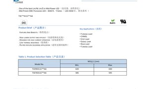
1.2 Key Applications
This LED series is particularly suited for automotive signal lighting and various indicator applications due to its color options and performance profile.
- Turning Lamp
- Center High-Mounted Stop Lamp (CHMSL)
- Stop Lamp
- Signal Lamp
- Rear Lamp
2. In-Depth Technical Parameter Analysis
All parameters are specified at a test condition of Forward Current (IF) = 150 mA, Ambient Temperature (Ta) = 25°C, and Relative Humidity (RH) = 60% unless otherwise noted. Measurement tolerances must be considered for design margins.
2.1 Electro-Optical Characteristics
The core performance metrics define the light output and basic electrical behavior under standard operating conditions.
- Typical Luminous Flux: 19 lm for both Red and Yellow variants at 150 mA. The minimum guaranteed value is 17 lm. Note that the luminous flux table is for reference, and actual measurements have a tolerance of ±7%.
- Dominant Wavelength (WD): Red: 620-630 nm; Yellow: 585-595 nm. This defines the perceived color of the LED.
- Viewing Angle (2θ1/2): A typical value of 120°, indicating a wide beam pattern suitable for area illumination and signaling.
2.2 Electrical and Thermal Parameters
These parameters are crucial for driver design and thermal management.
- Forward Voltage (VF): Red: Typ. 2.0V, Max. 2.4V; Yellow: Typ. 2.2V, Max. 2.4V at 150 mA. Tolerance is ±0.08V.
- Reverse Current (IR): Maximum 10 µA at a Reverse Voltage (VR) of 5V.
- Thermal Resistance, Junction to Solder Point (Rth j-sp): Red: 14 °C/W; Yellow: 16 °C/W. This low value is key to managing junction temperature.
- Electrostatic Discharge (ESD) Immunity: Withstands 8000V (Human Body Model), indicating good handling robustness.
2.3 Absolute Maximum Ratings
Exceeding these limits may cause permanent damage to the device. Operation should always remain within these boundaries.
- Forward Current (IF): Red: 350 mA (DC); Yellow: 240 mA (DC).
- Pulse Forward Current (IFP): Red: 400 mA; Yellow: 300 mA. Condition: Pulse Width ≤ 100 µs, Duty Cycle ≤ 1/10.
- Power Dissipation (PD): Red: 840 mW; Yellow: 624 mW.
- Reverse Voltage (VR): 5 V.
- Operating Temperature (Topr): -40°C to +105°C.
- Storage Temperature (Tstg): -40°C to +105°C.
- Junction Temperature (Tj): 125°C (maximum).
- Soldering Temperature (Tsld): 260°C for 10 seconds (or 230°C).
Critical Note: LED properties may degrade if operation exceeds the specified parameter range. Care must be taken to ensure power dissipation does not surpass the absolute maximum rating.
3. Performance Curve Analysis
Graphical data provides insight into the LED's behavior under varying conditions, which is essential for robust system design.
3.1 Relative Spectral Distribution
The spectral plot (Fig. 1) shows the narrow-band emission characteristic of these LEDs. The Red LED peaks in the 620-630 nm range, while the Yellow LED peaks in the 585-595 nm range. This information is vital for color-sensitive applications.
3.2 Forward Current Characteristics
Luminous Flux vs. Current (Fig. 2): The relative luminous flux increases with forward current but will eventually saturate. Operating at or below the recommended current ensures optimal efficiency and lifetime.
Forward Voltage vs. Current (Fig. 3): The V-I curve shows the typical diode behavior. The voltage increases logarithmically with current. This curve is necessary for designing constant-current drivers.
3.3 Temperature Dependence Characteristics
Luminous Flux vs. Ambient Temperature (Fig. 4): Luminous output decreases as ambient temperature rises. This derating must be accounted for in thermal design to maintain consistent light output.
Forward Voltage vs. Ambient Temperature (Fig. 5): Forward voltage typically decreases with increasing temperature (negative temperature coefficient). This can be used in some temperature-sensing circuits.
Maximum Forward Current vs. Ambient Temperature (Fig. 6): This derating curve is perhaps the most critical for reliability. It shows the maximum allowable continuous current as a function of the ambient temperature (assuming a junction-to-ambient thermal resistance, Rθj-a, of 40°C/W). For example, the Red LED's current must be reduced from 350 mA at ~81°C to about 104 mA at 105°C ambient. Ignoring this curve risks overheating and rapid lumen depreciation.
4. Binning System Explanation
To ensure color and brightness consistency in production, LEDs are sorted into bins. Designers should specify the required bin codes.
4.1 Wavelength (Color) Binning
The dominant wavelength is sorted into specific ranges (bins) with a measurement tolerance of ±1 nm.
- Red: Bin 1: 620-625 nm; Bin 2: 625-630 nm.
- Yellow: Bin 1: 585-590 nm; Bin 2: 590-595 nm.
4.2 Luminous Flux Binning
LEDs are grouped based on their light output at 150 mA, with a measurement tolerance of ±7%.
- Code AG: 14 lm to 18 lm
- Code AH: 18 lm to 22 lm
- Code AJ: 22 lm to 26 lm
The typical value of 19 lm falls within the AH bin.
4.3 Forward Voltage Binning
Forward voltage is also binned to aid in driver design for consistent current distribution in multi-LED arrays. The measurement tolerance is ±0.08V. The specific voltage bin codes and ranges (e.g., V1, V2) are defined in the full datasheet table (Table 7), categorizing the typical 2.0V-2.4V range.
5. Application and Design Guidelines
5.1 Thermal Management
Effective heat sinking is non-negotiable. Use the thermal resistance (Rth j-sp) value to calculate the junction temperature (Tj) rise above the solder point temperature. The formula is: ΔTj = PD * Rth j-sp. Ensure Tj remains below 125°C at all times, preferably lower for maximum lifetime. The derating curve (Fig. 6) provides a direct guideline for current limits based on ambient temperature.
5.2 Electrical Drive
These LEDs must be driven by a constant current source, not a constant voltage source. The driver should be designed to supply the required current (e.g., 150 mA) while accommodating the forward voltage bin range and its negative temperature coefficient. Consider implementing over-temperature protection to reduce current if the system overheats.
5.3 Soldering and Handling
Follow the recommended reflow profile with a peak temperature of 260°C for 10 seconds. Avoid mechanical stress on the package. Observe standard ESD precautions during handling and assembly, as specified by the 8000V HBM rating.
6. Technical Comparison and Considerations
The 3030 EMC package offers a balance between the lower-cost but thermally limited PLCC packages and the higher-power but more expensive ceramic-based packages. Its key differentiator is the improved thermal performance of the EMC material over standard plastics, allowing for higher drive currents and better lumen maintenance compared to traditional mid-power LEDs. When selecting a bin, consider the trade-off between tighter color consistency (narrower bins) and potential cost/availability.
7. Frequently Asked Questions (Based on Technical Parameters)
7.1 Can I drive this LED at 300 mA?
Driving the Red LED at 300 mA exceeds its absolute maximum DC current rating of 350 mA but is below the pulse rating. While it might produce more light initially, it will significantly increase the junction temperature, leading to rapid lumen depreciation, color shift, and reduced lifetime. It is not recommended for continuous operation. Always refer to the derating curve (Fig. 6) for the safe operating current at your specific ambient temperature.
7.2 Why is the thermal resistance specification important?
Thermal resistance (Rth j-sp) quantifies how easily heat flows from the LED junction (the hot spot) to the solder point on your board. A lower value (like 14 °C/W) means heat is removed more efficiently. This directly controls the junction temperature, which is the primary factor affecting LED lifespan, efficiency, and color stability. Poor thermal management is the most common cause of premature LED failure.
7.3 What does the ±7% tolerance on luminous flux mean for my design?
It means that an LED from the AH bin (18-22 lm) could measure as low as 16.7 lm (18 lm * 0.93) or as high as 23.5 lm (22 lm * 1.07) in your system, even if it's correctly binned. Therefore, your optical design should have enough margin to accommodate this variation to ensure the final product meets its brightness specifications.
8. Operating Principle and Technology Trend
8.1 Basic Operating Principle
This LED is a semiconductor diode. When a forward voltage exceeding its characteristic threshold is applied, electrons and holes recombine within the active region of the semiconductor chip, releasing energy in the form of photons (light). The specific material composition of the semiconductor layers determines the wavelength (color) of the emitted light. The EMC package serves to protect the delicate chip, provide a primary lens to shape the light beam, and offer a robust thermal path to dissipate heat.
8.2 Industry Trends
The mid-power LED segment continues to evolve towards higher efficacy (lm/W) and improved reliability at competitive costs. Trends include the adoption of advanced phosphor technologies for white LEDs, further refinement of EMC and other package materials for better thermal and humidity resistance, and the integration of more consistent chip-level performance. The drive for miniaturization and higher density in lighting modules also pushes for packages that can deliver more light from a smaller footprint with excellent thermal characteristics, a trend exemplified by packages like the 3030.
LED Specification Terminology
Complete explanation of LED technical terms
Photoelectric Performance
| Term | Unit/Representation | Simple Explanation | Why Important |
|---|---|---|---|
| Luminous Efficacy | lm/W (lumens per watt) | Light output per watt of electricity, higher means more energy efficient. | Directly determines energy efficiency grade and electricity cost. |
| Luminous Flux | lm (lumens) | Total light emitted by source, commonly called "brightness". | Determines if the light is bright enough. |
| Viewing Angle | ° (degrees), e.g., 120° | Angle where light intensity drops to half, determines beam width. | Affects illumination range and uniformity. |
| CCT (Color Temperature) | K (Kelvin), e.g., 2700K/6500K | Warmth/coolness of light, lower values yellowish/warm, higher whitish/cool. | Determines lighting atmosphere and suitable scenarios. |
| CRI / Ra | Unitless, 0–100 | Ability to render object colors accurately, Ra≥80 is good. | Affects color authenticity, used in high-demand places like malls, museums. |
| SDCM | MacAdam ellipse steps, e.g., "5-step" | Color consistency metric, smaller steps mean more consistent color. | Ensures uniform color across same batch of LEDs. |
| Dominant Wavelength | nm (nanometers), e.g., 620nm (red) | Wavelength corresponding to color of colored LEDs. | Determines hue of red, yellow, green monochrome LEDs. |
| Spectral Distribution | Wavelength vs intensity curve | Shows intensity distribution across wavelengths. | Affects color rendering and quality. |
Electrical Parameters
| Term | Symbol | Simple Explanation | Design Considerations |
|---|---|---|---|
| Forward Voltage | Vf | Minimum voltage to turn on LED, like "starting threshold". | Driver voltage must be ≥Vf, voltages add up for series LEDs. |
| Forward Current | If | Current value for normal LED operation. | Usually constant current drive, current determines brightness & lifespan. |
| Max Pulse Current | Ifp | Peak current tolerable for short periods, used for dimming or flashing. | Pulse width & duty cycle must be strictly controlled to avoid damage. |
| Reverse Voltage | Vr | Max reverse voltage LED can withstand, beyond may cause breakdown. | Circuit must prevent reverse connection or voltage spikes. |
| Thermal Resistance | Rth (°C/W) | Resistance to heat transfer from chip to solder, lower is better. | High thermal resistance requires stronger heat dissipation. |
| ESD Immunity | V (HBM), e.g., 1000V | Ability to withstand electrostatic discharge, higher means less vulnerable. | Anti-static measures needed in production, especially for sensitive LEDs. |
Thermal Management & Reliability
| Term | Key Metric | Simple Explanation | Impact |
|---|---|---|---|
| Junction Temperature | Tj (°C) | Actual operating temperature inside LED chip. | Every 10°C reduction may double lifespan; too high causes light decay, color shift. |
| Lumen Depreciation | L70 / L80 (hours) | Time for brightness to drop to 70% or 80% of initial. | Directly defines LED "service life". |
| Lumen Maintenance | % (e.g., 70%) | Percentage of brightness retained after time. | Indicates brightness retention over long-term use. |
| Color Shift | Δu′v′ or MacAdam ellipse | Degree of color change during use. | Affects color consistency in lighting scenes. |
| Thermal Aging | Material degradation | Deterioration due to long-term high temperature. | May cause brightness drop, color change, or open-circuit failure. |
Packaging & Materials
| Term | Common Types | Simple Explanation | Features & Applications |
|---|---|---|---|
| Package Type | EMC, PPA, Ceramic | Housing material protecting chip, providing optical/thermal interface. | EMC: good heat resistance, low cost; Ceramic: better heat dissipation, longer life. |
| Chip Structure | Front, Flip Chip | Chip electrode arrangement. | Flip chip: better heat dissipation, higher efficacy, for high-power. |
| Phosphor Coating | YAG, Silicate, Nitride | Covers blue chip, converts some to yellow/red, mixes to white. | Different phosphors affect efficacy, CCT, and CRI. |
| Lens/Optics | Flat, Microlens, TIR | Optical structure on surface controlling light distribution. | Determines viewing angle and light distribution curve. |
Quality Control & Binning
| Term | Binning Content | Simple Explanation | Purpose |
|---|---|---|---|
| Luminous Flux Bin | Code e.g., 2G, 2H | Grouped by brightness, each group has min/max lumen values. | Ensures uniform brightness in same batch. |
| Voltage Bin | Code e.g., 6W, 6X | Grouped by forward voltage range. | Facilitates driver matching, improves system efficiency. |
| Color Bin | 5-step MacAdam ellipse | Grouped by color coordinates, ensuring tight range. | Guarantees color consistency, avoids uneven color within fixture. |
| CCT Bin | 2700K, 3000K etc. | Grouped by CCT, each has corresponding coordinate range. | Meets different scene CCT requirements. |
Testing & Certification
| Term | Standard/Test | Simple Explanation | Significance |
|---|---|---|---|
| LM-80 | Lumen maintenance test | Long-term lighting at constant temperature, recording brightness decay. | Used to estimate LED life (with TM-21). |
| TM-21 | Life estimation standard | Estimates life under actual conditions based on LM-80 data. | Provides scientific life prediction. |
| IESNA | Illuminating Engineering Society | Covers optical, electrical, thermal test methods. | Industry-recognized test basis. |
| RoHS / REACH | Environmental certification | Ensures no harmful substances (lead, mercury). | Market access requirement internationally. |
| ENERGY STAR / DLC | Energy efficiency certification | Energy efficiency and performance certification for lighting. | Used in government procurement, subsidy programs, enhances competitiveness. |