Table of Contents
- 1. Product Overview
- 1.1 Target Applications
- 2. Technical Parameter Deep-Dive
- 2.1 Absolute Maximum Ratings
- 2.2 Electro-Optical Characteristics
- 3. Binning System Explanation
- 3.1 Product Number Breakdown
- 3.2 Chromaticity Coordinate Binning
- 3.3 Luminous Flux Binning
- 3.4 Forward Voltage Binning
- 4. Performance Curve Analysis & Design Considerations
- 4.1 Current vs. Luminous Flux (L-I Relationship)
- 4.2 Thermal Management
- 4.3 Driver Design
- 5. Mechanical & Packaging Information
- 5.1 Package Outline
- 5.2 Polarity Identification
- 6. Soldering & Assembly Guidelines
- 7. Application Suggestions & Design Notes
- 7.1 Typical Application Circuits
- 7.2 PCB Layout Considerations
- 8. Technical Comparison & Differentiation
- 9. Frequently Asked Questions (Based on Parameters)
- 10. Operating Principle & Technology
- LED Specification Terminology
- Photoelectric Performance
- Electrical Parameters
- Thermal Management & Reliability
- Packaging & Materials
- Quality Control & Binning
- Testing & Certification
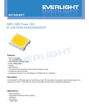
1. Product Overview
The 67-23ST series is a compact, high-performance SMD (Surface-Mount Device) Mid-Power LED housed in a standard PLCC-2 (Plastic Leaded Chip Carrier) package. It is designed to emit white light across various correlated color temperatures (CCT). Its core advantages include high luminous efficacy, excellent color rendering capabilities (with CRI options up to 90 minimum), a wide 120-degree viewing angle, and low power consumption. The package is lead-free, halogen-free, and compliant with major environmental directives like RoHS and EU REACH, making it suitable for a broad range of general and decorative lighting applications where reliability and quality of light are paramount.
1.1 Target Applications
- General Indoor and Ambient Lighting
- Decorative and Architectural Lighting
- Entertainment and Stage Lighting
- Indicator and Backlighting Applications
- Switch and Control Panel Illumination
2. Technical Parameter Deep-Dive
2.1 Absolute Maximum Ratings
These ratings define the limits beyond which permanent damage to the device may occur. Operation should be maintained within these boundaries.
- Forward Current (IF): 20 mA (Continuous)
- Peak Forward Current (IFP): 40 mA (Pulsed, Duty Cycle 1/10, Pulse Width 10ms)
- Power Dissipation (Pd): 1100 mW
- Operating Temperature (Topr): -40°C to +85°C
- Storage Temperature (Tstg): -40°C to +100°C
- Thermal Resistance (Rth J-S): 12 °C/W (Junction to Soldering Point)
- Maximum Junction Temperature (Tj): 115 °C
- Soldering Temperature: Reflow: 260°C for 10 sec max; Hand Soldering: 350°C for 3 sec max.
Note: This device is sensitive to Electrostatic Discharge (ESD). Proper ESD handling procedures must be followed during assembly and handling.
2.2 Electro-Optical Characteristics
Measured at a solder point temperature (Tsoldering) of 25°C with a forward current (IF) of 17mA, which is the typical operating condition.
- Luminous Flux (Φ): Minimum values range from 140 lm to 155 lm depending on CCT (see Mass Production List). Typical tolerance is ±11%.
- Forward Voltage (VF): Maximum rating is 55.0V. Typical binning ranges from 50V to 55V. Tolerance is ±0.1V.
- Color Rendering Index (CRI/Ra): Minimum values from 60 to 90 are available (see CRI Index Table). For the mass production list, Ra (Min.) is 80. Tolerance is ±2.
- R9 Value: Specified as 0 (minimum) for the listed products, indicating a potential limitation in deep red saturation which is common for some white LED phosphor systems.
- Viewing Angle (2θ1/2): 120 degrees (typical). This wide angle ensures uniform light distribution.
3. Binning System Explanation
The product uses an ANSI-standard binning system to ensure color and flux consistency. The part number contains codes for these bins.
3.1 Product Number Breakdown
Example: 67-23ST/KKE-H27140550Z2/2T
- 67-23ST/: Package type (PLCC-2).
- KKE: Internal code.
- H: CRI Index Code (H = CRI 90 Min.). For mass production models, 'H' corresponds to CRI 80 Min. (See CRI Table).
- 27: Color Temperature Code (27 = 2700K).
- 140: Minimum Luminous Flux Code (140 = 140 lm min).
- 550: Forward Voltage Index (550 = 55.0V max).
- Z2: Forward Current Index (Z2 = IF 17mA).
- 2T: Packing quantity per reel (2T = specific reel count).
3.2 Chromaticity Coordinate Binning
The LED's white point (color) is tightly controlled within defined regions on the CIE 1931 chromaticity diagram. The datasheet provides specific (x, y) coordinate boxes for each CCT (2700K, 3000K, 3500K, etc.) and sub-bin (A, B, C...). For example, for 2700K, bins like 27K-A, 27K-B define different quadrilateral areas ensuring the emitted white light falls within a precise color range, typically within a 2- or 4-step MacAdam ellipse, guaranteeing minimal visual color difference between LEDs from the same bin.
3.3 Luminous Flux Binning
Flux is binned in steps. For instance, at 2700K:
- Bin 140L10: 140 lm (Min.) to 150 lm (Max.)
- Bin 150L10: 150 lm (Min.) to 160 lm (Max.)
3.4 Forward Voltage Binning
Voltage is binned in 1V steps from 50V to 55V (e.g., 50J: 50-51V, 51J: 51-52V). This helps in designing more efficient driver circuits by matching LED voltage ranges, potentially simplifying current regulation.
4. Performance Curve Analysis & Design Considerations
While specific graphs (IV, temperature vs. flux) are not provided in the excerpt, key relationships can be inferred from the parameters.
4.1 Current vs. Luminous Flux (L-I Relationship)
The luminous flux is specified at 17mA. Operating above this current (up to the absolute max of 20mA) will increase light output but also increase power dissipation (VF * IF) and junction temperature. The relationship is generally linear within a range, but efficiency (lumens per watt) may drop at higher currents due to increased heat.
4.2 Thermal Management
With a thermal resistance (Rth J-S) of 12°C/W, proper PCB thermal design is crucial. For example, at the rated 17mA and a typical VF of ~52.5V, power dissipation is ~0.89W. The temperature rise from the solder point to the junction would be approximately 0.89W * 12°C/W = ~10.7°C. To keep the junction temperature (Tj) below 115°C, the solder point temperature must be maintained below ~104°C. This necessitates adequate copper area on the PCB (thermal pads) and possibly airflow in the final application.
4.3 Driver Design
The high forward voltage (up to 55V) suggests this LED likely contains multiple LED chips connected in series within the single package. A constant-current driver is mandatory, not a constant-voltage source. The driver must be designed to handle the maximum VF of the selected voltage bin and provide a stable 17mA (or other designed current within limits).
5. Mechanical & Packaging Information
5.1 Package Outline
The device uses the common PLCC-2 surface-mount package. While exact dimensions (L x W x H) are not specified in the provided text, the PLCC-2 form factor is industry-standard. The top view is the primary emitting surface. The package resin is water-clear, which is optimal for achieving high light extraction efficiency and maintaining color consistency.
5.2 Polarity Identification
PLCC-2 packages typically have a marked cathode (often a green dot, a notch, or a cut corner on the lens or body). Correct polarity must be observed during PCB assembly. Reversed polarity will prevent the LED from illuminating and may stress the device.
6. Soldering & Assembly Guidelines
- Reflow Soldering: Maximum peak temperature of 260°C should not be exceeded for more than 10 seconds. A standard lead-free reflow profile is applicable.
- Hand Soldering: If necessary, the iron tip temperature should be limited to 350°C, and contact time should not exceed 3 seconds per pad to prevent thermal damage to the plastic package and the internal die attach.
- Storage: Store in dry, anti-static conditions within the specified storage temperature range (-40°C to +100°C).
7. Application Suggestions & Design Notes
7.1 Typical Application Circuits
These LEDs require an external constant current driver. A simple circuit involves a DC power supply, a switching constant-current LED driver IC, and the LED module. The driver IC must be selected based on the input voltage range, required output current (17mA), and the total forward voltage of the LED string (if multiple 67-23ST LEDs are used in series).
7.2 PCB Layout Considerations
- Thermal Pads: Design the PCB footprint with sufficient copper area connected to the LED's thermal pad (if present) or the cathode/anode pads to act as a heat sink. Thermal vias to inner or bottom layers can significantly improve heat dissipation.
- Electrical Isolation: Ensure proper creepage and clearance distances, especially given the relatively high operating voltage (up to 55V).
8. Technical Comparison & Differentiation
The 67-23ST differentiates itself through its combination of high voltage operation (simplifying series connections for higher voltage supplies), high CRI options (up to 90), and wide viewing angle. Compared to lower-voltage mid-power LEDs, it reduces the current requirement for a given power level, which can minimize resistive losses in traces and connectors. Its compliance with halogen-free and stringent environmental standards makes it suitable for eco-sensitive and demanding markets.
9. Frequently Asked Questions (Based on Parameters)
Q: Can I drive this LED with a 12V or 24V power supply directly?
A: No. The forward voltage is much higher (50-55V). A constant-current driver circuit that can boost the input voltage to exceed the LED's VF is required.
Q: What does an R9 value of 0 mean for lighting quality?
A> A low or zero R9 value indicates the LED may not render deep red colors vividly. This is acceptable for many general lighting applications but might be a consideration for retail lighting (meat, produce, fabrics) or museum lighting where accurate red rendition is critical. Check the specific CRI bin for R9 specifications if available.
Q: How many LEDs can I connect in series?
A> It depends on your driver's maximum output voltage compliance. For example, with a driver rated for 150V max and using LEDs with a max VF of 55V, you could theoretically connect 2 LEDs in series (110V max) with a safe margin. Always design with worst-case (Max. VF) values.
10. Operating Principle & Technology
This is a phosphor-converted white LED. The core is a semiconductor chip based on InGaN (Indium Gallium Nitride) materials, which emits blue light when forward biased. This blue light excites a yellow (and often red) phosphor coating inside the package. The mixture of the remaining blue light and the converted yellow/red light results in the perception of white light. The exact blend of phosphors determines the Correlated Color Temperature (CCT - 2700K, 4000K, etc.) and the Color Rendering Index (CRI). The PLCC-2 package provides mechanical protection, environmental sealing, and houses the primary optical lens that shapes the 120-degree beam.
LED Specification Terminology
Complete explanation of LED technical terms
Photoelectric Performance
| Term | Unit/Representation | Simple Explanation | Why Important |
|---|---|---|---|
| Luminous Efficacy | lm/W (lumens per watt) | Light output per watt of electricity, higher means more energy efficient. | Directly determines energy efficiency grade and electricity cost. |
| Luminous Flux | lm (lumens) | Total light emitted by source, commonly called "brightness". | Determines if the light is bright enough. |
| Viewing Angle | ° (degrees), e.g., 120° | Angle where light intensity drops to half, determines beam width. | Affects illumination range and uniformity. |
| CCT (Color Temperature) | K (Kelvin), e.g., 2700K/6500K | Warmth/coolness of light, lower values yellowish/warm, higher whitish/cool. | Determines lighting atmosphere and suitable scenarios. |
| CRI / Ra | Unitless, 0–100 | Ability to render object colors accurately, Ra≥80 is good. | Affects color authenticity, used in high-demand places like malls, museums. |
| SDCM | MacAdam ellipse steps, e.g., "5-step" | Color consistency metric, smaller steps mean more consistent color. | Ensures uniform color across same batch of LEDs. |
| Dominant Wavelength | nm (nanometers), e.g., 620nm (red) | Wavelength corresponding to color of colored LEDs. | Determines hue of red, yellow, green monochrome LEDs. |
| Spectral Distribution | Wavelength vs intensity curve | Shows intensity distribution across wavelengths. | Affects color rendering and quality. |
Electrical Parameters
| Term | Symbol | Simple Explanation | Design Considerations |
|---|---|---|---|
| Forward Voltage | Vf | Minimum voltage to turn on LED, like "starting threshold". | Driver voltage must be ≥Vf, voltages add up for series LEDs. |
| Forward Current | If | Current value for normal LED operation. | Usually constant current drive, current determines brightness & lifespan. |
| Max Pulse Current | Ifp | Peak current tolerable for short periods, used for dimming or flashing. | Pulse width & duty cycle must be strictly controlled to avoid damage. |
| Reverse Voltage | Vr | Max reverse voltage LED can withstand, beyond may cause breakdown. | Circuit must prevent reverse connection or voltage spikes. |
| Thermal Resistance | Rth (°C/W) | Resistance to heat transfer from chip to solder, lower is better. | High thermal resistance requires stronger heat dissipation. |
| ESD Immunity | V (HBM), e.g., 1000V | Ability to withstand electrostatic discharge, higher means less vulnerable. | Anti-static measures needed in production, especially for sensitive LEDs. |
Thermal Management & Reliability
| Term | Key Metric | Simple Explanation | Impact |
|---|---|---|---|
| Junction Temperature | Tj (°C) | Actual operating temperature inside LED chip. | Every 10°C reduction may double lifespan; too high causes light decay, color shift. |
| Lumen Depreciation | L70 / L80 (hours) | Time for brightness to drop to 70% or 80% of initial. | Directly defines LED "service life". |
| Lumen Maintenance | % (e.g., 70%) | Percentage of brightness retained after time. | Indicates brightness retention over long-term use. |
| Color Shift | Δu′v′ or MacAdam ellipse | Degree of color change during use. | Affects color consistency in lighting scenes. |
| Thermal Aging | Material degradation | Deterioration due to long-term high temperature. | May cause brightness drop, color change, or open-circuit failure. |
Packaging & Materials
| Term | Common Types | Simple Explanation | Features & Applications |
|---|---|---|---|
| Package Type | EMC, PPA, Ceramic | Housing material protecting chip, providing optical/thermal interface. | EMC: good heat resistance, low cost; Ceramic: better heat dissipation, longer life. |
| Chip Structure | Front, Flip Chip | Chip electrode arrangement. | Flip chip: better heat dissipation, higher efficacy, for high-power. |
| Phosphor Coating | YAG, Silicate, Nitride | Covers blue chip, converts some to yellow/red, mixes to white. | Different phosphors affect efficacy, CCT, and CRI. |
| Lens/Optics | Flat, Microlens, TIR | Optical structure on surface controlling light distribution. | Determines viewing angle and light distribution curve. |
Quality Control & Binning
| Term | Binning Content | Simple Explanation | Purpose |
|---|---|---|---|
| Luminous Flux Bin | Code e.g., 2G, 2H | Grouped by brightness, each group has min/max lumen values. | Ensures uniform brightness in same batch. |
| Voltage Bin | Code e.g., 6W, 6X | Grouped by forward voltage range. | Facilitates driver matching, improves system efficiency. |
| Color Bin | 5-step MacAdam ellipse | Grouped by color coordinates, ensuring tight range. | Guarantees color consistency, avoids uneven color within fixture. |
| CCT Bin | 2700K, 3000K etc. | Grouped by CCT, each has corresponding coordinate range. | Meets different scene CCT requirements. |
Testing & Certification
| Term | Standard/Test | Simple Explanation | Significance |
|---|---|---|---|
| LM-80 | Lumen maintenance test | Long-term lighting at constant temperature, recording brightness decay. | Used to estimate LED life (with TM-21). |
| TM-21 | Life estimation standard | Estimates life under actual conditions based on LM-80 data. | Provides scientific life prediction. |
| IESNA | Illuminating Engineering Society | Covers optical, electrical, thermal test methods. | Industry-recognized test basis. |
| RoHS / REACH | Environmental certification | Ensures no harmful substances (lead, mercury). | Market access requirement internationally. |
| ENERGY STAR / DLC | Energy efficiency certification | Energy efficiency and performance certification for lighting. | Used in government procurement, subsidy programs, enhances competitiveness. |