Table of Contents
- 1. Product Overview
- 2. Technical Parameter Deep Dive
- 2.1 Absolute Maximum Ratings
- 2.2 Electro-Optical Characteristics
- 3. Binning System Explanation
- 3.1 Luminous Intensity Binning
- 3.2 Dominant Wavelength Binning
- 3.3 Forward Voltage Binning
- 4. Performance Curve Analysis
- 5. Mechanical & Package Information
- 5.1 Package Dimensions
- 6. Soldering & Assembly Guidelines
- 6.1 Lead Forming
- 6.2 Storage Conditions
- 6.3 Soldering Process
- 7. Packaging & Ordering Information
- 7.1 Packing Specification
- 7.2 Label Information
- 8. Application Suggestions
- 8.1 Typical Application Scenarios
- 8.2 Design Considerations
- 9. Technical Comparison & Differentiation
- 10. Frequently Asked Questions (Based on Technical Parameters)
- 10.1 What is the difference between Peak Wavelength and Dominant Wavelength?
- 10.2 Can I drive this LED at 30mA continuously for maximum brightness?
- 10.3 How do I interpret the bin codes (e.g., H1-2, 1b) when ordering?
- 10.4 Why is the storage life limited to 3 months, and what happens after that?
- 11. Design-in Case Study
- 12. Operating Principle
- 13. Technology Trends
1. Product Overview
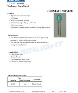
This document details the specifications for a precision optical performance oval LED. The device is engineered specifically for applications in passenger information signs and similar display systems. Its core design principle focuses on providing a well-defined spatial radiation pattern, which is crucial for achieving uniform illumination and color mixing in graphic displays.
The LED features a high luminous intensity output, making it suitable for outdoor and high-ambient-light environments. The oval shape of the lens is a key differentiator, creating an asymmetric viewing angle that is optimized for horizontal signage. This characteristic, combined with a wide viewing angle of 110 degrees in one axis and 40 degrees in the perpendicular axis, ensures good visibility from various perspectives. The encapsulation material utilizes UV-resistant epoxy, enhancing long-term reliability and color stability when exposed to sunlight, which is essential for outdoor advertising and variable message signs.
2. Technical Parameter Deep Dive
2.1 Absolute Maximum Ratings
The device is designed to operate within strict electrical and thermal limits to ensure reliability. The absolute maximum ratings define the thresholds beyond which permanent damage may occur.
- Forward Current (IF): 30 mA (DC). This is the maximum continuous current that can be applied.
- Pulse Forward Current (IFP): 100 mA, permissible under pulsed conditions with a duty cycle of 1/10 at 1 kHz. This allows for brief periods of higher brightness.
- Reverse Voltage (VR): 5 V. Exceeding this voltage in reverse bias can damage the LED junction.
- Power Dissipation (Pd): 100 mW. This parameter limits the total electrical power that can be converted into heat.
- Operating & Storage Temperature: The device can function from -40°C to +85°C and can be stored from -40°C to +100°C.
- Soldering Temperature: Withstands 260°C for a maximum of 5 seconds, which is compatible with standard lead-free soldering processes.
- Electrostatic Discharge (ESD): Withstands 1000V (Human Body Model), indicating a moderate level of ESD protection. Proper ESD handling procedures are still recommended.
2.2 Electro-Optical Characteristics
These parameters are measured under standard test conditions (Ta=25°C, IF=20mA) and define the core performance of the LED.
- Luminous Intensity (IV): Ranges from a minimum of 720 mcd to a maximum of 1450 mcd. The typical value falls within this range, offering high brightness.
- Viewing Angle (2θ1/2): Asymmetric at 110° x 40°. The larger 110° angle is typically aligned for wide horizontal viewing, while the 40° angle provides a more focused vertical beam.
- Peak Wavelength (λp): Typically 468 nm, indicating the point of maximum spectral power emission.
- Dominant Wavelength (λd): Ranges from 465 nm to 475 nm. This defines the perceived color of the light (blue).
- Spectral Half Width (Δλ): Typically 26 nm. This measures the spectral purity; a narrower width indicates a more saturated blue color.
- Forward Voltage (VF): Ranges from 2.8V to 3.6V at 20mA. This is critical for driver circuit design to ensure proper current regulation.
- Reverse Current (IR): Maximum of 50 μA at VR=5V, indicating good junction quality.
3. Binning System Explanation
To ensure color and brightness consistency in production, LEDs are sorted into bins based on key parameters.
3.1 Luminous Intensity Binning
LEDs are categorized into four ranks (G2, H1, H2, J1) based on their measured luminous intensity at 20mA.
- G2: 720 ~ 860 mcd
- H1: 860 ~ 1030 mcd
- H2: 1030 ~ 1210 mcd
- J1: 1210 ~ 1450 mcd
The measurement uncertainty is ±10%. Designers can select bins to achieve specific brightness levels or uniformity across a display.
3.2 Dominant Wavelength Binning
Color consistency is managed through four wavelength ranks (1a, 1b, 2a, 2b).
- 1a: 465.0 ~ 467.5 nm
- 1b: 467.5 ~ 470.0 nm
- 2a: 470.0 ~ 472.5 nm
- 2b: 472.5 ~ 475.0 nm
The measurement uncertainty is ±1.0 nm. This binning is crucial for applications requiring precise color matching, such as full-color signs where blue mixes with other colors.
3.3 Forward Voltage Binning
Forward voltage is sorted into four ranks (0, 1, 2, 3) to aid in driver design and power management.
- 0: 2.8 ~ 3.0 V
- 1: 3.0 ~ 3.2 V
- 2: 3.2 ~ 3.4 V
- 3: 3.4 ~ 3.6 V
The measurement uncertainty is ±0.1V. Using LEDs from the same voltage bin can simplify current-limiting resistor calculations in series or parallel arrays.
4. Performance Curve Analysis
The datasheet references typical electro-optical characteristic curves. While the specific graphs are not provided in the text, standard curves for such LEDs would typically include:
- Relative Luminous Intensity vs. Forward Current (I-V Curve): Shows how light output increases with current, typically in a near-linear relationship up to the maximum rated current. It highlights the importance of constant current drive for stable brightness.
- Relative Luminous Intensity vs. Ambient Temperature: Demonstrates the thermal derating of light output. Luminous intensity generally decreases as junction temperature rises, which is a critical consideration for thermal management in enclosed signs.
- Forward Voltage vs. Junction Temperature: Shows the negative temperature coefficient of VF. The forward voltage drops as temperature increases, which can affect the performance of simple resistor-based drive circuits.
- Spectral Distribution: A graph plotting relative intensity against wavelength, showing the peak at ~468 nm and the 26 nm half-width, confirming the blue color emission.
- Viewing Angle Pattern: A polar plot illustrating the asymmetric radiation pattern (110° x 40°), crucial for optical design in signage to direct light where needed.
5. Mechanical & Package Information
5.1 Package Dimensions
The LED features a specific oval-lens package. Key dimensional notes from the datasheet include:
- All dimensions are in millimeters (mm).
- The standard tolerance is ±0.25 mm unless otherwise specified.
- The maximum protrusion of resin under the flange is 1.5 mm.
- After the tie-bar is cut, bare copper alloy is exposed at that portion. This area may be susceptible to oxidation if not properly protected during assembly or conformal coating.
The exact dimensional drawing is referenced but not detailed in the text. The package is designed for through-hole mounting (DIP).
6. Soldering & Assembly Guidelines
6.1 Lead Forming
- Bending must occur at least 3 mm from the base of the epoxy bulb to prevent stress on the internal die and wire bonds.
- Lead forming must be completed before the soldering process.
- Avoid applying stress to the LED package during bending.
- Cut leadframes at room temperature. High-temperature cutting can induce thermal shock.
- PCB holes must align precisely with LED leads. Misalignment causing lead stress can degrade the epoxy resin and LED performance.
6.2 Storage Conditions
- Recommended storage: ≤30°C and ≤70% Relative Humidity (RH).
- Maximum storage life under these conditions: 3 months from shipment.
- For longer storage (up to 1 year), place LEDs in a sealed container with a nitrogen atmosphere and desiccant.
- Avoid rapid temperature changes in high humidity to prevent condensation, which can lead to moisture ingress and subsequent failure during soldering ("popcorning").
6.3 Soldering Process
Detailed recommendations are provided for both hand and wave soldering.
- General Rule: Maintain a minimum distance of 3 mm from the solder joint to the epoxy bulb.
- Hand Soldering: Iron tip temperature ≤300°C (for a max. 30W iron). Soldering time ≤3 seconds per lead.
- Wave/DIP Soldering:
- Preheat temperature: ≤100°C (for ≤60 seconds).
- Soldering bath temperature: ≤260°C.
- Soldering time in bath: ≤5 seconds.
- Avoid stress on leads while the LED is at high temperature.
- Do not solder (dip or hand) an LED more than once.
- Protect the epoxy bulb from mechanical shock/vibration until it cools to room temperature post-soldering.
- Avoid rapid cooling from peak soldering temperature.
A recommended soldering temperature profile is referenced, typically showing a ramp-up, preheat, spike to peak temperature (260°C), and controlled cooldown.
7. Packaging & Ordering Information
7.1 Packing Specification
The LEDs are packaged with ESD protection and clear labeling.
- Primary Packaging: 500 pieces per anti-electrostatic bag.
- Secondary Packaging: 5 bags are placed into one inner carton (totaling 2,500 pieces).
- Tertiary Packaging: 10 inner cartons are packed into one master outside carton (totaling 25,000 pieces).
7.2 Label Information
Labels on the bag and cartons contain critical information for traceability and correct application:
- CPN (Customer Part Number): The customer's internal reference.
- P/N (Production Part Number): The manufacturer's part number (e.g., 5484BN/BADC-AGJA/P/MS).
- QTY (Quantity): Number of pieces in the package.
- CAT (Category): Combined rank code for Luminous Intensity and Forward Voltage bins (e.g., H1-2).
- HUE: Rank code for the Dominant Wavelength bin (e.g., 1b).
- REF (Reference): Additional reference information.
- LOT No: Traceable manufacturing lot number.
- Production Place: Indicates the country of manufacture.
8. Application Suggestions
8.1 Typical Application Scenarios
As specified, this LED is designed for:
- Color Graphic Signs & Message Boards: Its high intensity and oval pattern make it ideal for backlighting or direct illumination of signs, ensuring readability.
- Variable Message Signs (VMS): Used on highways, airports, and public transport systems. The binning system allows for consistent color and brightness across large, multi-LED displays.
- Commercial Outdoor Advertising: The UV-resistant epoxy and robust design support long-term reliability in harsh outdoor environments with exposure to sunlight and weather.
- Passenger Information Signs: The specific spatial radiation pattern is matched for mixing with red and green LEDs to create various colors in full-color displays.
8.2 Design Considerations
- Drive Circuit: Use a constant current driver set to 20mA (or lower for reduced brightness/power) to ensure stable operation and longevity. Account for the VF binning when designing series strings.
- Thermal Management: Although power dissipation is only 100mW per LED, high-density arrays in enclosed signs can generate significant heat. Ensure adequate ventilation or heatsinking to maintain junction temperature within safe limits, preserving light output and lifespan.
- Optical Design: Leverage the 110° x 40° viewing angle. Orient the LED so the 110° axis covers the desired horizontal viewing area. Secondary optics (diffusers, lenses) may be used to further shape the beam if needed.
- ESD Protection: Implement standard ESD precautions during handling and assembly, despite the 1kV ESD rating.
9. Technical Comparison & Differentiation
While a direct comparison with other part numbers is not in the datasheet, key differentiating features of this LED can be inferred:
- Oval Lens vs. Standard Round Lens: The primary differentiator. An oval lens creates a rectangular radiation pattern, which is more efficient for illuminating rectangular sign areas compared to a circular pattern from a round lens, reducing wasted light.
- Matched Radiation for Color Mixing: The datasheet explicitly states the radiation pattern is matched for red/green/blue mixing applications. This suggests careful optical design to ensure uniform color blending at various viewing angles in RGB pixel clusters.
- High Intensity Binning: Offering bins up to 1450mcd provides a high-brightness option suitable for sunlight-readable applications.
- UV-Resistant Epoxy: A critical feature for outdoor longevity, preventing yellowing and transmittance loss of the encapsulant over time.
10. Frequently Asked Questions (Based on Technical Parameters)
10.1 What is the difference between Peak Wavelength and Dominant Wavelength?
Peak Wavelength (λp ~468 nm) is the wavelength at which the LED emits the most optical power. Dominant Wavelength (λd 465-475 nm) is the wavelength of monochromatic light that would appear to have the same color as the LED to the human eye. Dominant wavelength is more relevant for color specification in displays.
10.2 Can I drive this LED at 30mA continuously for maximum brightness?
Yes, 30mA is the absolute maximum continuous forward current. However, operating at the maximum rating will generate more heat and may accelerate lumen depreciation over time. For optimal lifespan and reliability, driving at or below the test current of 20mA is recommended unless the higher brightness is essential and thermal management is excellent.
10.3 How do I interpret the bin codes (e.g., H1-2, 1b) when ordering?
The "CAT" code (e.g., H1-2) combines the luminous intensity bin (H1 = 860-1030 mcd) and the forward voltage bin (2 = 3.2-3.4V). The "HUE" code (e.g., 1b = 467.5-470.0 nm) specifies the dominant wavelength bin. Specifying these bins ensures you receive LEDs with tightly grouped performance characteristics for consistent display results.
10.4 Why is the storage life limited to 3 months, and what happens after that?
The 3-month limit under standard factory conditions (≤30°C/70%RH) is a precaution against moisture absorption through the plastic package. After 3 months, the moisture level may exceed safe limits for soldering, risking internal delamination or cracking during the high-temperature reflow process ("popcorning"). For longer storage, the nitrogen-packed, desiccated environment prevents moisture ingress, extending the safe storage time to one year.
11. Design-in Case Study
Scenario: Designing a High-Brightness Outdoor Variable Message Sign (VMS)
- Requirement Analysis: The sign must be sunlight-readable, operate in temperatures from -20°C to +60°C, and have a uniform color appearance.
- LED Selection: This oval blue LED is chosen for its high intensity (selecting J1 bin for maximum brightness), UV-resistant epoxy for outdoor use, and matched radiation pattern for color mixing with red and green partners.
- Electrical Design: LEDs are arranged in series strings. The driver is a constant current type set to 18mA (slightly below 20mA for margin). The worst-case VF (3.6V from bin 3) is used to calculate the minimum required driver voltage for each string.
- Thermal Design: The PCB is metal-core (MCPCB) to efficiently conduct heat away from the LED array. Thermal simulations are run to ensure the LED junction temperature stays below 85°C at the maximum ambient temperature.
- Optical & Mechanical Design: LEDs are mounted with their 110° axis aligned horizontally across the sign. A secondary diffuser is placed over the array to blend individual LED points into a smooth, uniform panel of light.
- Procurement & Assembly: LEDs are ordered with specific bin codes (e.g., J1 for intensity, 2a for wavelength) to ensure consistency across all production batches. Strict adherence to the soldering profile and storage guidelines is maintained during assembly.
12. Operating Principle
This LED is based on an InGaN (Indium Gallium Nitride) semiconductor chip. When a forward voltage exceeding the diode's threshold (approximately 2.8-3.6V) is applied, electrons and holes are injected into the active region of the semiconductor. They recombine, releasing energy in the form of photons. The specific composition of the InGaN alloy determines the bandgap energy, which in turn defines the wavelength of the emitted light—in this case, in the blue spectrum (~468 nm). The oval-shaped epoxy lens surrounding the chip acts as a primary optical element, refracting and shaping the emitted light into the desired 110° x 40° radiation pattern.
13. Technology Trends
LEDs for signage continue to evolve. While this datasheet represents a mature through-hole (DIP) product, general industry trends include:
- Increased Efficiency (lm/W): Newer chip technologies and phosphors allow for higher luminous output at the same or lower drive currents, reducing power consumption and thermal load.
- Surface-Mount Device (SMD) Adoption: SMD packages allow for higher density, automated assembly, and often better thermal paths compared to traditional DIP packages, though DIP remains relevant for certain high-power or legacy designs.
- Improved Color Rendering & Gamut: Advances in semiconductor materials and phosphor systems enable LEDs with narrower spectral peaks and more saturated colors, expanding the color gamut of full-color displays.
- Integrated Smart Features: Some modern signage LEDs incorporate built-in drivers (IC-driven LEDs) or addressability, simplifying system design.
- Enhanced Reliability & Lifetime: Ongoing improvements in packaging materials, such as more robust silicones replacing epoxies in some high-power applications, lead to longer operational lifespans and better resistance to harsh environments.
The product described in this datasheet sits within this landscape as a specialized, optically optimized component for a specific application niche where its oval beam pattern and high-intensity output provide distinct advantages.
LED Specification Terminology
Complete explanation of LED technical terms
Photoelectric Performance
| Term | Unit/Representation | Simple Explanation | Why Important |
|---|---|---|---|
| Luminous Efficacy | lm/W (lumens per watt) | Light output per watt of electricity, higher means more energy efficient. | Directly determines energy efficiency grade and electricity cost. |
| Luminous Flux | lm (lumens) | Total light emitted by source, commonly called "brightness". | Determines if the light is bright enough. |
| Viewing Angle | ° (degrees), e.g., 120° | Angle where light intensity drops to half, determines beam width. | Affects illumination range and uniformity. |
| CCT (Color Temperature) | K (Kelvin), e.g., 2700K/6500K | Warmth/coolness of light, lower values yellowish/warm, higher whitish/cool. | Determines lighting atmosphere and suitable scenarios. |
| CRI / Ra | Unitless, 0–100 | Ability to render object colors accurately, Ra≥80 is good. | Affects color authenticity, used in high-demand places like malls, museums. |
| SDCM | MacAdam ellipse steps, e.g., "5-step" | Color consistency metric, smaller steps mean more consistent color. | Ensures uniform color across same batch of LEDs. |
| Dominant Wavelength | nm (nanometers), e.g., 620nm (red) | Wavelength corresponding to color of colored LEDs. | Determines hue of red, yellow, green monochrome LEDs. |
| Spectral Distribution | Wavelength vs intensity curve | Shows intensity distribution across wavelengths. | Affects color rendering and quality. |
Electrical Parameters
| Term | Symbol | Simple Explanation | Design Considerations |
|---|---|---|---|
| Forward Voltage | Vf | Minimum voltage to turn on LED, like "starting threshold". | Driver voltage must be ≥Vf, voltages add up for series LEDs. |
| Forward Current | If | Current value for normal LED operation. | Usually constant current drive, current determines brightness & lifespan. |
| Max Pulse Current | Ifp | Peak current tolerable for short periods, used for dimming or flashing. | Pulse width & duty cycle must be strictly controlled to avoid damage. |
| Reverse Voltage | Vr | Max reverse voltage LED can withstand, beyond may cause breakdown. | Circuit must prevent reverse connection or voltage spikes. |
| Thermal Resistance | Rth (°C/W) | Resistance to heat transfer from chip to solder, lower is better. | High thermal resistance requires stronger heat dissipation. |
| ESD Immunity | V (HBM), e.g., 1000V | Ability to withstand electrostatic discharge, higher means less vulnerable. | Anti-static measures needed in production, especially for sensitive LEDs. |
Thermal Management & Reliability
| Term | Key Metric | Simple Explanation | Impact |
|---|---|---|---|
| Junction Temperature | Tj (°C) | Actual operating temperature inside LED chip. | Every 10°C reduction may double lifespan; too high causes light decay, color shift. |
| Lumen Depreciation | L70 / L80 (hours) | Time for brightness to drop to 70% or 80% of initial. | Directly defines LED "service life". |
| Lumen Maintenance | % (e.g., 70%) | Percentage of brightness retained after time. | Indicates brightness retention over long-term use. |
| Color Shift | Δu′v′ or MacAdam ellipse | Degree of color change during use. | Affects color consistency in lighting scenes. |
| Thermal Aging | Material degradation | Deterioration due to long-term high temperature. | May cause brightness drop, color change, or open-circuit failure. |
Packaging & Materials
| Term | Common Types | Simple Explanation | Features & Applications |
|---|---|---|---|
| Package Type | EMC, PPA, Ceramic | Housing material protecting chip, providing optical/thermal interface. | EMC: good heat resistance, low cost; Ceramic: better heat dissipation, longer life. |
| Chip Structure | Front, Flip Chip | Chip electrode arrangement. | Flip chip: better heat dissipation, higher efficacy, for high-power. |
| Phosphor Coating | YAG, Silicate, Nitride | Covers blue chip, converts some to yellow/red, mixes to white. | Different phosphors affect efficacy, CCT, and CRI. |
| Lens/Optics | Flat, Microlens, TIR | Optical structure on surface controlling light distribution. | Determines viewing angle and light distribution curve. |
Quality Control & Binning
| Term | Binning Content | Simple Explanation | Purpose |
|---|---|---|---|
| Luminous Flux Bin | Code e.g., 2G, 2H | Grouped by brightness, each group has min/max lumen values. | Ensures uniform brightness in same batch. |
| Voltage Bin | Code e.g., 6W, 6X | Grouped by forward voltage range. | Facilitates driver matching, improves system efficiency. |
| Color Bin | 5-step MacAdam ellipse | Grouped by color coordinates, ensuring tight range. | Guarantees color consistency, avoids uneven color within fixture. |
| CCT Bin | 2700K, 3000K etc. | Grouped by CCT, each has corresponding coordinate range. | Meets different scene CCT requirements. |
Testing & Certification
| Term | Standard/Test | Simple Explanation | Significance |
|---|---|---|---|
| LM-80 | Lumen maintenance test | Long-term lighting at constant temperature, recording brightness decay. | Used to estimate LED life (with TM-21). |
| TM-21 | Life estimation standard | Estimates life under actual conditions based on LM-80 data. | Provides scientific life prediction. |
| IESNA | Illuminating Engineering Society | Covers optical, electrical, thermal test methods. | Industry-recognized test basis. |
| RoHS / REACH | Environmental certification | Ensures no harmful substances (lead, mercury). | Market access requirement internationally. |
| ENERGY STAR / DLC | Energy efficiency certification | Energy efficiency and performance certification for lighting. | Used in government procurement, subsidy programs, enhances competitiveness. |