Table of Contents
- 1. Product Overview
- 1.1 Core Advantages and Target Market
- 2. Technical Parameter Deep Dive
- 2.1 Absolute Maximum Ratings
- 2.2 Electro-Optical Characteristics
- 3. Binning System Explanation
- 3.1 Luminous Intensity Binning
- 3.2 Dominant Wavelength Binning
- 4. Performance Curve Analysis
- 4.1 Relative Intensity vs. Wavelength
- 4.2 Directivity Pattern
- 4.3 Forward Current vs. Forward Voltage (I-V Curve)
- 4.4 Relative Intensity vs. Forward Current
- 4.5 Temperature Dependence
- 5. Mechanical and Package Information
- 5.1 Package Dimensions
- 6. Soldering and Assembly Guidelines
- 6.1 Lead Forming
- 6.2 Storage
- 6.3 Soldering
- 7. Packaging and Ordering Information
- 7.1 Moisture Resistant Packing
- 7.2 Label Explanation
- 7.3 Carrier Tape and Taping Dimensions
- 7.4 Packing Process and Quantity
- 7.5 Model Number Designation
- 8. Application Suggestions
- 8.1 Typical Application Scenarios
- 8.2 Design Considerations
- 9. Technical Comparison and Differentiation
- 10. Frequently Asked Questions (Based on Technical Parameters)
- 10.1 What is the difference between peak wavelength and dominant wavelength?
- 10.2 Can I drive this LED at 30mA for more brightness?
- 10.3 How do I interpret the binning codes on the label?
- 10.4 What are the implications of the 260°C for 5 seconds soldering rating?
- 11. Practical Use Case Example
- 12. Operating Principle Introduction
- 13. Technology Trends (Objective Context)
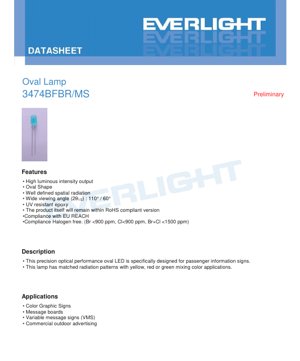
1. Product Overview
This document details the specifications for a precision optical performance oval LED lamp. The device is engineered to deliver high luminous intensity within a well-defined spatial radiation pattern, making it particularly suitable for applications requiring clear and visible signage.
1.1 Core Advantages and Target Market
The primary advantages of this LED include its oval shape, which contributes to a specific radiation pattern, and a wide viewing angle of 110° horizontally and 60° vertically. It is constructed with UV-resistant epoxy and complies with RoHS, REACH, and halogen-free standards (Br <900 ppm, Cl <900 ppm, Br+Cl <1500 ppm). The lamp is specifically designed for passenger information systems, including color graphic signs, message boards, variable message signs (VMS), and commercial outdoor advertising.
2. Technical Parameter Deep Dive
2.1 Absolute Maximum Ratings
The device must not be operated beyond these limits to prevent permanent damage. Key ratings include a reverse voltage (VR) of 5V, a continuous forward current (IF) of 20mA, and a peak forward current (IFP) of 100mA under a 1/10 duty cycle at 1kHz. The maximum power dissipation (Pd) is 100mW. The operating temperature range is from -40°C to +85°C, with storage allowed from -40°C to +100°C. The soldering temperature is specified as 260°C for a maximum of 5 seconds.
2.2 Electro-Optical Characteristics
All characteristics are measured at an ambient temperature (Ta) of 25°C and a forward current of 20mA.
- Luminous Intensity (Iv): Ranges from a minimum of 550 mcd to a maximum of 1130 mcd, with a typical value of 800 mcd.
- Viewing Angle (2θ1/2): 110° (X-axis) / 60° (Y-axis).
- Peak Wavelength (λp): Typically 468 nm.
- Dominant Wavelength (λd): Ranges from 460 nm to 475 nm.
- Forward Voltage (VF): Between 2.4V and 3.6V.
- Reverse Current (IR): Maximum of 50 μA at VR=5V.
3. Binning System Explanation
The LEDs are sorted into bins based on key parameters to ensure consistency in application.
3.1 Luminous Intensity Binning
Bins are defined by codes BA, BB, BC, and BD, with minimum and maximum luminous intensity values as follows: BA (550-660 mcd), BB (660-790 mcd), BC (790-945 mcd), BD (945-1130 mcd). A general tolerance of ±10% applies.
3.2 Dominant Wavelength Binning
Wavelength bins are coded B1 through B5, covering the range from 460 nm to 475 nm in increments of approximately 3 nm. The tolerance for dominant wavelength is ±1 nm.
4. Performance Curve Analysis
The datasheet provides several characteristic curves measured at Ta=25°C.
4.1 Relative Intensity vs. Wavelength
This curve shows the spectral power distribution, with a peak around 468 nm and a typical spectral bandwidth (Δλ) of 20 nm, confirming the blue color emission.
4.2 Directivity Pattern
A polar plot illustrates the spatial radiation pattern, highlighting the asymmetric 110° x 60° viewing angle which is crucial for sign design.
4.3 Forward Current vs. Forward Voltage (I-V Curve)
This graph shows the exponential relationship between current and voltage, typical for a diode. It is essential for designing the current-limiting circuitry.
4.4 Relative Intensity vs. Forward Current
The curve demonstrates how light output increases with forward current, up to the maximum rated current.
4.5 Temperature Dependence
Two curves show the effects of ambient temperature:
Relative Intensity vs. Ambient Temp: Light output typically decreases as temperature increases.
Forward Current vs. Ambient Temp: Illustrates how the required current for a given voltage changes with temperature.
5. Mechanical and Package Information
5.1 Package Dimensions
A detailed dimensional drawing is provided. Key notes specify that all dimensions are in millimeters with a standard tolerance of ±0.25 mm unless otherwise stated. The maximum protrusion of resin under the flange is 1.5 mm.
6. Soldering and Assembly Guidelines
6.1 Lead Forming
- Bends must be made at least 3mm from the base of the epoxy bulb.
- Forming must be completed before soldering.
- Avoid stressing the package to prevent damage or breakage.
- Cut leads at room temperature.
- Ensure PCB holes align perfectly with LED leads to avoid mounting stress.
6.2 Storage
- Recommended storage conditions are ≤30°C and ≤70% Relative Humidity.
- The shelf life after shipment is 3 months. For longer storage (up to 1 year), use a sealed container with a nitrogen atmosphere and desiccant.
- Avoid rapid temperature changes in humid environments to prevent condensation.
6.3 Soldering
During soldering, maintain a distance of more than 3mm from the solder joint to the epoxy bulb. Do not solder beyond the base of the tie bar. Follow the specified reflow profile (260°C for 5 sec max).
7. Packaging and Ordering Information
7.1 Moisture Resistant Packing
The LEDs are supplied in moisture-resistant packaging.
7.2 Label Explanation
The reel label includes fields for Customer's Product Number (CPN), Product Number (P/N), Packing Quantity (QTY), and the binning codes for Luminous Intensity (CAT), Dominant Wavelength (HUE), and Forward Voltage (REF), along with the Lot Number.
7.3 Carrier Tape and Taping Dimensions
Detailed drawings and a table specify the carrier tape dimensions, including feed hole diameter (D=4.00mm), component pitch (F=2.54mm), and overall tape width (W3=18.00mm).
7.4 Packing Process and Quantity
Standard packing includes 2500 pieces per inner carton and 10 inner cartons (25,000 pieces total) per outside carton.
7.5 Model Number Designation
The part number follows the structure: 3474 B F B R - □ □ □ □. The specific meaning of each character segment is implied by the product description (e.g., 3474 base type, B for blue, etc.), though a full decoding table is not explicitly provided in the excerpt.
8. Application Suggestions
8.1 Typical Application Scenarios
- Passenger Information Signs: The oval beam pattern is matched for mixing with yellow, red, or green filters in color graphic signs.
- Variable Message Signs (VMS): High intensity ensures readability in various ambient light conditions.
- Commercial Outdoor Advertising: UV-resistant epoxy provides durability for outdoor use.
8.2 Design Considerations
- Current Drive: Use a constant current driver set to 20mA or below, referencing the I-V curve for voltage drop.
- Thermal Management: Although power is low, ensure the operating environment stays within the -40°C to +85°C range for reliable performance and longevity.
- Optical Design: Leverage the 110°x60° viewing angle for optimal sign layout and viewer coverage.
- Binning Selection: Choose appropriate luminous intensity (CAT) and wavelength (HUE) bins based on the required brightness and color consistency for the application.
9. Technical Comparison and Differentiation
While a direct comparison with other products is not provided, the key differentiating factors of this LED can be inferred from its specifications:
- Oval Lens vs. Standard Round Lens: Provides a tailored, rectangular radiation pattern ideal for sign pixels, potentially offering better optical efficiency for sign applications than a standard radial pattern.
- Specific Viewing Angle: The 110°/60° asymmetry is optimized for typical viewing geometries of roadside or indoor signs.
- Compliance: Simultaneous compliance with RoHS, REACH, and strict halogen-free standards may offer an advantage in markets with stringent environmental regulations.
10. Frequently Asked Questions (Based on Technical Parameters)
10.1 What is the difference between peak wavelength and dominant wavelength?
Peak wavelength (λp=468 nm) is the wavelength at which the emitted optical power is maximum. Dominant wavelength (λd=460-475 nm) is the single wavelength perceived by the human eye that matches the color of the light. Both are important, with dominant wavelength being more critical for color definition in signs.
10.2 Can I drive this LED at 30mA for more brightness?
No. The Absolute Maximum Rating for continuous forward current (IF) is 20mA. Exceeding this rating risks reducing the device's lifetime or causing immediate failure. For higher brightness, select an LED from a higher luminous intensity bin (e.g., BD).
10.3 How do I interpret the binning codes on the label?
The "CAT" code (e.g., BC) corresponds to the luminous intensity range. The "HUE" code (e.g., B3) corresponds to the dominant wavelength range. Using LEDs from the same bin ensures consistent brightness and color across your display.
10.4 What are the implications of the 260°C for 5 seconds soldering rating?
This defines the maximum thermal profile the LED package can withstand during reflow or hand soldering. The temperature measured at the LED leads should not exceed 260°C, and the time above the solder's liquidus temperature (which is lower than 260°C) should be controlled to minimize thermal stress on the epoxy and internal die.
11. Practical Use Case Example
Scenario: Designing a monochrome blue passenger information sign for a bus station.
- Component Selection: Choose this oval LED for its suited beam pattern and high intensity.
- Binning: Specify a tight wavelength bin (e.g., B3 only) to ensure uniform blue color across all characters in the sign. Select a luminous intensity bin (e.g., BB or BC) based on required viewing distance and ambient light.
- Circuit Design: Design a constant current driver circuit providing 20mA per LED string. Calculate the required supply voltage based on the number of LEDs in series and the maximum forward voltage (VF=3.6V).
- PCB Layout: Place mounting holes according to the package drawing. Ensure a 3mm clearance between the solder pad and the LED body.
- Assembly: Follow the lead forming and soldering guidelines. Use the recommended reflow profile.
- Testing: Verify light output and viewing angle meet the sign's design requirements.
12. Operating Principle Introduction
This is a semiconductor light-emitting diode (LED). When a forward voltage exceeding its threshold (approximately 2.4-3.6V) is applied, electrons and holes recombine in the active region (InGaN chip material). This recombination process releases energy in the form of photons (light). The specific material composition (InGaN) determines the photon energy and thus the blue color of the emitted light (wavelength ~468 nm). The oval-shaped epoxy lens then encapsulates the chip and shapes the emitted light into the desired 110°x60° radiation pattern.
13. Technology Trends (Objective Context)
LEDs for signage continue to evolve. General industry trends, which provide context for this component's place in the market, include:
- Increased Efficiency: Ongoing development aims for higher luminous efficacy (more light output per electrical watt), which could allow for lower power consumption or brighter displays in future iterations.
- Improved Color Consistency: Advances in epitaxial growth and binning processes lead to tighter wavelength and intensity distributions, enabling more uniform and vibrant displays.
- Enhanced Reliability: Research into more robust packaging materials and thermal management extends operational lifetime, especially critical for 24/7 outdoor applications.
- Miniaturization: The drive for higher resolution displays pushes for smaller LED packages with maintained or improved optical performance.
This specific oval LED represents a specialized solution optimized for a particular application segment (information signs), balancing optical design, reliability, and regulatory compliance.
LED Specification Terminology
Complete explanation of LED technical terms
Photoelectric Performance
| Term | Unit/Representation | Simple Explanation | Why Important |
|---|---|---|---|
| Luminous Efficacy | lm/W (lumens per watt) | Light output per watt of electricity, higher means more energy efficient. | Directly determines energy efficiency grade and electricity cost. |
| Luminous Flux | lm (lumens) | Total light emitted by source, commonly called "brightness". | Determines if the light is bright enough. |
| Viewing Angle | ° (degrees), e.g., 120° | Angle where light intensity drops to half, determines beam width. | Affects illumination range and uniformity. |
| CCT (Color Temperature) | K (Kelvin), e.g., 2700K/6500K | Warmth/coolness of light, lower values yellowish/warm, higher whitish/cool. | Determines lighting atmosphere and suitable scenarios. |
| CRI / Ra | Unitless, 0–100 | Ability to render object colors accurately, Ra≥80 is good. | Affects color authenticity, used in high-demand places like malls, museums. |
| SDCM | MacAdam ellipse steps, e.g., "5-step" | Color consistency metric, smaller steps mean more consistent color. | Ensures uniform color across same batch of LEDs. |
| Dominant Wavelength | nm (nanometers), e.g., 620nm (red) | Wavelength corresponding to color of colored LEDs. | Determines hue of red, yellow, green monochrome LEDs. |
| Spectral Distribution | Wavelength vs intensity curve | Shows intensity distribution across wavelengths. | Affects color rendering and quality. |
Electrical Parameters
| Term | Symbol | Simple Explanation | Design Considerations |
|---|---|---|---|
| Forward Voltage | Vf | Minimum voltage to turn on LED, like "starting threshold". | Driver voltage must be ≥Vf, voltages add up for series LEDs. |
| Forward Current | If | Current value for normal LED operation. | Usually constant current drive, current determines brightness & lifespan. |
| Max Pulse Current | Ifp | Peak current tolerable for short periods, used for dimming or flashing. | Pulse width & duty cycle must be strictly controlled to avoid damage. |
| Reverse Voltage | Vr | Max reverse voltage LED can withstand, beyond may cause breakdown. | Circuit must prevent reverse connection or voltage spikes. |
| Thermal Resistance | Rth (°C/W) | Resistance to heat transfer from chip to solder, lower is better. | High thermal resistance requires stronger heat dissipation. |
| ESD Immunity | V (HBM), e.g., 1000V | Ability to withstand electrostatic discharge, higher means less vulnerable. | Anti-static measures needed in production, especially for sensitive LEDs. |
Thermal Management & Reliability
| Term | Key Metric | Simple Explanation | Impact |
|---|---|---|---|
| Junction Temperature | Tj (°C) | Actual operating temperature inside LED chip. | Every 10°C reduction may double lifespan; too high causes light decay, color shift. |
| Lumen Depreciation | L70 / L80 (hours) | Time for brightness to drop to 70% or 80% of initial. | Directly defines LED "service life". |
| Lumen Maintenance | % (e.g., 70%) | Percentage of brightness retained after time. | Indicates brightness retention over long-term use. |
| Color Shift | Δu′v′ or MacAdam ellipse | Degree of color change during use. | Affects color consistency in lighting scenes. |
| Thermal Aging | Material degradation | Deterioration due to long-term high temperature. | May cause brightness drop, color change, or open-circuit failure. |
Packaging & Materials
| Term | Common Types | Simple Explanation | Features & Applications |
|---|---|---|---|
| Package Type | EMC, PPA, Ceramic | Housing material protecting chip, providing optical/thermal interface. | EMC: good heat resistance, low cost; Ceramic: better heat dissipation, longer life. |
| Chip Structure | Front, Flip Chip | Chip electrode arrangement. | Flip chip: better heat dissipation, higher efficacy, for high-power. |
| Phosphor Coating | YAG, Silicate, Nitride | Covers blue chip, converts some to yellow/red, mixes to white. | Different phosphors affect efficacy, CCT, and CRI. |
| Lens/Optics | Flat, Microlens, TIR | Optical structure on surface controlling light distribution. | Determines viewing angle and light distribution curve. |
Quality Control & Binning
| Term | Binning Content | Simple Explanation | Purpose |
|---|---|---|---|
| Luminous Flux Bin | Code e.g., 2G, 2H | Grouped by brightness, each group has min/max lumen values. | Ensures uniform brightness in same batch. |
| Voltage Bin | Code e.g., 6W, 6X | Grouped by forward voltage range. | Facilitates driver matching, improves system efficiency. |
| Color Bin | 5-step MacAdam ellipse | Grouped by color coordinates, ensuring tight range. | Guarantees color consistency, avoids uneven color within fixture. |
| CCT Bin | 2700K, 3000K etc. | Grouped by CCT, each has corresponding coordinate range. | Meets different scene CCT requirements. |
Testing & Certification
| Term | Standard/Test | Simple Explanation | Significance |
|---|---|---|---|
| LM-80 | Lumen maintenance test | Long-term lighting at constant temperature, recording brightness decay. | Used to estimate LED life (with TM-21). |
| TM-21 | Life estimation standard | Estimates life under actual conditions based on LM-80 data. | Provides scientific life prediction. |
| IESNA | Illuminating Engineering Society | Covers optical, electrical, thermal test methods. | Industry-recognized test basis. |
| RoHS / REACH | Environmental certification | Ensures no harmful substances (lead, mercury). | Market access requirement internationally. |
| ENERGY STAR / DLC | Energy efficiency certification | Energy efficiency and performance certification for lighting. | Used in government procurement, subsidy programs, enhances competitiveness. |