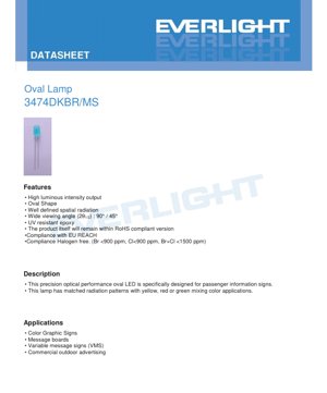
1. Product Overview
This document details the specifications for a precision oval-shaped LED lamp. The primary design objective of this component is to serve as a high-performance light source for passenger information systems and various signage applications. Its defining feature is an oval lens geometry that creates a well-defined, asymmetric spatial radiation pattern, making it particularly suitable for color-mixing applications in signs requiring yellow, red, or green output through secondary optics or filters.
The device is constructed using UV-resistant epoxy material, ensuring long-term reliability and color stability in outdoor environments. It complies with key environmental regulations including RoHS, EU REACH, and halogen-free standards, with bromine and chlorine content strictly controlled.
1.1 Core Advantages and Target Market
The core advantages of this LED include its high luminous intensity output, specialized oval radiation pattern for uniform signage illumination, and robust construction for demanding applications. The target market encompasses manufacturers of transportation infrastructure, commercial advertising, and public information systems. Key application areas are:
- Color Graphic Signs and Message Boards
- Variable Message Signs (VMS) for traffic management
- Commercial Outdoor Advertising Displays
2. Technical Parameters: In-Depth Objective Interpretation
2.1 Absolute Maximum Ratings
The device's operational limits are defined under specific ambient conditions (Ta=25°C). Exceeding these ratings may cause permanent damage.
- Reverse Voltage (VR): 5V. The maximum voltage that can be applied in the reverse direction across the LED terminals.
- Forward Current (IF): 30 mA (continuous). The recommended maximum DC current for reliable operation.
- Peak Forward Current (IFP): 100 mA. This is permissible only under pulsed conditions (duty cycle 1/10 @ 1kHz) and should not be used for continuous operation.
- Power Dissipation (Pd): 110 mW. The maximum power the package can dissipate as heat.
- Operating & Storage Temperature: Ranges from -40°C to +85°C (operating) and -40°C to +100°C (storage).
- Soldering Temperature: Withstands 260°C for 5 seconds, compatible with standard reflow soldering processes.
2.2 Electro-Optical Characteristics
Performance is specified at a standard test current of IF=20mA and Ta=25°C.
- Luminous Intensity (Iv): Ranges from a minimum of 934 mcd to a maximum of 2130 mcd, with a typical value of 1140 mcd. This high intensity is crucial for daylight visibility in signage.
- Viewing Angle (2θ1/2): Asymmetric at 90° (X-axis) by 45° (Y-axis). This oval pattern is engineered to match the typical aspect ratio of informational text and symbols on signs.
- Peak & Dominant Wavelength: The chip emits in the blue spectrum. Peak wavelength (λp) is typically 468 nm. Dominant wavelength (λd) ranges from 460 nm to 475 nm, categorized into bins.
- Forward Voltage (VF): Between 2.4V and 3.4V at 20mA. Designers must account for this voltage drop when designing driver circuits.
- Reverse Current (IR): Maximum of 50 µA at VR=5V, indicating good junction quality.
3. Binning System Explanation
To ensure color and brightness consistency in end products, LEDs are sorted into bins based on key parameters.
3.1 Luminous Intensity Binning
Intensity is categorized into five bins (BA to BE), each with a defined min/max range measured at IF=20mA. The total tolerance is ±10%. For example, bin BC covers 1340 to 1600 mcd. System designers should specify the required bin or be aware of potential brightness variations across different production lots.
3.2 Dominant Wavelength Binning
Wavelength is categorized into five bins (B1 to B5), each spanning 3 nm, from 460-463 nm (B1) to 472-475 nm (B5). The tolerance is ±1 nm. This precise binning allows for tight color control, which is especially important when the blue LED is used with phosphors or filters to create other colors.
4. Performance Curve Analysis
The datasheet provides several characteristic curves that are vital for understanding device behavior under different conditions.
4.1 Spectral Distribution and Directivity
The Relative Intensity vs. Wavelength curve shows a narrow spectral bandwidth (Δλ) of approximately 20 nm, centered in the blue region. The Directivity plot visually confirms the asymmetric oval radiation pattern, with intensity dropping to half its peak value at the specified 90° and 45° angles.
4.2 Electrical and Thermal Characteristics
The Forward Current vs. Forward Voltage (I-V) curve exhibits the typical exponential relationship of a diode. The Relative Intensity vs. Forward Current curve shows that light output increases with current but may become sub-linear at higher currents due to thermal effects. The Relative Intensity vs. Ambient Temperature and Forward Current vs. Ambient Temperature curves demonstrate the negative impact of rising temperature on both light output and the required driving current for a fixed voltage, highlighting the importance of thermal management in the application design.
5. Mechanical and Package Information
5.1 Package Dimensions and Drawing
The mechanical drawing specifies the oval lamp's physical footprint. Key dimensions include the lead spacing (pitch), overall body size, and the protrusion of the resin lens. All dimensions are in millimeters with a standard tolerance of ±0.25 mm unless otherwise noted. The maximum protrusion of the resin below the flange is 1.5 mm, which is important for clearance in the final assembly.
5.2 Polarity Identification and Pad Design
Polarity is indicated by the physical structure of the leads (typically a longer lead or a flat side on the package). The datasheet drawing should be consulted to identify the anode and cathode. PCB pad design should match the recommended footprint to ensure proper soldering and mechanical stability.
6. Soldering and Assembly Guidelines
6.1 Lead Forming and Handling
- Bending must occur at least 3 mm from the base of the epoxy bulb to avoid stress cracks.
- Lead forming must be completed before the soldering process.
- Excessive stress on the package during handling or insertion into a PCB can damage the internal die attach or wire bonds, degrading performance or causing failure.
- Leads should be cut at room temperature.
6.2 Storage Conditions
To prevent moisture absorption which can cause \"popcorning\" during reflow, LEDs should be stored at ≤30°C and ≤70% Relative Humidity. The shelf life from shipment is 3 months. For longer storage (up to one year), devices must be kept in a sealed, moisture-barrier bag with desiccant and in a nitrogen atmosphere.
6.3 Soldering Process
During wave or hand soldering, the solder joint must be at least 3 mm away from the epoxy body to prevent thermal shock and resin damage. The device is rated for a peak soldering temperature of 260°C for 5 seconds, which aligns with standard lead-free reflow profiles.
7. Packaging and Ordering Information
7.1 Moisture-Resistant Packing
The components are supplied in moisture-resistant packing, typically involving carrier tape and reel. The datasheet includes detailed dimensions for the carrier tape, including pocket pitch (P=12.70 mm), tape width (W3=18.00 mm), and other critical dimensions for automated pick-and-place equipment.
7.2 Label Explanation and Packing Quantities
The reel label contains crucial information: Customer Part Number (CPN), Manufacturer Part Number (P/N), Quantity (QTY), and the specific Binning Codes for Luminous Intensity (CAT), Dominant Wavelength (HUE), and Forward Voltage (REF). The standard packing quantity is 2500 pieces per inner carton, with 10 inner cartons (25,000 pieces) per master outside carton.
7.3 Model Number Designation
The part number 3474DKBR/MS follows a structured format where \"3474\" likely indicates the series or package, \"D\" may denote the color (Blue/Diffused), and subsequent letters specify performance bins or other variants. The placeholder squares (□□□□) at the end are for specifying the exact bin codes (e.g., CAT and HUE) when ordering.
8. Application Recommendations
8.1 Typical Application Circuits
This LED should be driven by a constant current source, not a constant voltage source, to ensure stable light output and prevent thermal runaway. A simple series resistor can be used with a stable DC voltage supply, calculated as R = (Vsupply - VF) / IF. For example, with a 5V supply and a typical VF of 3.0V at 20mA, R = (5-3)/0.02 = 100 Ω. The resistor power rating should be I2R = 0.04W, so a 1/8W or 1/4W resistor is sufficient.
8.2 Design Considerations
- Thermal Management: Although power dissipation is low, maintaining a low junction temperature is key to long-term reliability and stable light output, especially in enclosed signs or high ambient temperatures.
- Optical Integration: The oval beam pattern is designed to work with diffusers, light guides, or color filters commonly used in signage. The orientation of the LED (which axis is 90° vs. 45°) must be considered during PCB layout.
- ESD Protection: While not explicitly stated as sensitive, implementing standard ESD precautions during handling and assembly is considered good practice for all semiconductor devices.
9. Technical Comparison and Differentiation
The primary differentiation of this LED lies in its oval radiation pattern. Most standard LEDs have a circular (symmetric) viewing angle. This specialized pattern provides more efficient light distribution for rectangular sign elements, potentially reducing the number of LEDs needed for uniform illumination compared to using circular-pattern LEDs. Furthermore, its high luminous intensity binning (up to 2130 mcd) makes it competitive for applications requiring high brightness.
10. Frequently Asked Questions (Based on Technical Parameters)
Q: Can I drive this LED at its maximum continuous current of 30mA?
A: Yes, but you must ensure adequate thermal management. Operating at 30mA will produce higher light output but also generate more heat, which can reduce lifespan and cause wavelength shift. The 20mA test condition is the standard for specifying performance.
Q: What is the difference between Peak Wavelength and Dominant Wavelength?
A> Peak Wavelength (λp) is the wavelength at which the emission spectrum has its highest intensity. Dominant Wavelength (λd) is the single wavelength of monochromatic light that would match the perceived color of the LED. λd is more relevant for colorimetric applications.
Q: Why is the storage condition so specific (3 months, then nitrogen)?
A: The epoxy package can absorb moisture from the air. During the high-temperature reflow soldering process, this trapped moisture can vaporize rapidly, creating internal pressure that can delaminate the package or crack the epoxy—a phenomenon known as \"popcorning.\" The moisture-sensitive level (MSL) rating dictates these storage and handling requirements.
11. Practical Use Case Example
Scenario: Designing a Single-Line Variable Message Sign (VMS) for a highway.
The sign requires bright, evenly illuminated characters. The designer selects this oval LED. Multiple LEDs are placed behind a segmented diffuser panel forming each character. The LEDs are oriented so that the 90° wide axis aligns with the horizontal width of the character stroke, and the 45° narrow axis aligns with the vertical height. This orientation, combined with the diffuser, ensures that light is spread evenly across the width of the stroke without excessive spill into adjacent segments, improving contrast and readability. A constant-current driver board is designed to supply 20mA to each series string of LEDs, with the appropriate bin codes (e.g., BC for intensity, B4 for wavelength) specified in the bill of materials to ensure uniformity across all signs.
12. Operating Principle Introduction
This is a semiconductor light-emitting diode. It is based on an InGaN (Indium Gallium Nitride) chip material. When a forward voltage exceeding the diode's threshold is applied, electrons and holes recombine within the active region of the semiconductor junction. This recombination process releases energy in the form of photons (light). The specific bandgap energy of the InGaN material determines that the emitted photons are in the blue wavelength range (approximately 468 nm). The blue light exits through a molded epoxy lens which is diffused (indicated by \"MS\" likely meaning Milky White or Diffused) to scatter the light and shape it into the specified oval beam pattern.
13. Technology Trends and Context
LEDs for signage and professional lighting continue to evolve towards higher efficiency (more lumens per watt), improved color consistency through tighter binning, and enhanced reliability. The use of specialized optics, as seen in this oval lens, is a trend to increase application efficiency by directing light precisely where it is needed, reducing optical losses. Furthermore, compliance with environmental regulations (RoHS, REACH, Halogen-Free) is now a standard requirement in the industry, driven by global environmental policies and customer demand for sustainable products. The focus on moisture-resistant packaging and detailed handling instructions reflects the industry's move towards more robust and reliable manufacturing processes for surface-mount devices.
LED Specification Terminology
Complete explanation of LED technical terms
Photoelectric Performance
| Term | Unit/Representation | Simple Explanation | Why Important |
|---|---|---|---|
| Luminous Efficacy | lm/W (lumens per watt) | Light output per watt of electricity, higher means more energy efficient. | Directly determines energy efficiency grade and electricity cost. |
| Luminous Flux | lm (lumens) | Total light emitted by source, commonly called "brightness". | Determines if the light is bright enough. |
| Viewing Angle | ° (degrees), e.g., 120° | Angle where light intensity drops to half, determines beam width. | Affects illumination range and uniformity. |
| CCT (Color Temperature) | K (Kelvin), e.g., 2700K/6500K | Warmth/coolness of light, lower values yellowish/warm, higher whitish/cool. | Determines lighting atmosphere and suitable scenarios. |
| CRI / Ra | Unitless, 0–100 | Ability to render object colors accurately, Ra≥80 is good. | Affects color authenticity, used in high-demand places like malls, museums. |
| SDCM | MacAdam ellipse steps, e.g., "5-step" | Color consistency metric, smaller steps mean more consistent color. | Ensures uniform color across same batch of LEDs. |
| Dominant Wavelength | nm (nanometers), e.g., 620nm (red) | Wavelength corresponding to color of colored LEDs. | Determines hue of red, yellow, green monochrome LEDs. |
| Spectral Distribution | Wavelength vs intensity curve | Shows intensity distribution across wavelengths. | Affects color rendering and quality. |
Electrical Parameters
| Term | Symbol | Simple Explanation | Design Considerations |
|---|---|---|---|
| Forward Voltage | Vf | Minimum voltage to turn on LED, like "starting threshold". | Driver voltage must be ≥Vf, voltages add up for series LEDs. |
| Forward Current | If | Current value for normal LED operation. | Usually constant current drive, current determines brightness & lifespan. |
| Max Pulse Current | Ifp | Peak current tolerable for short periods, used for dimming or flashing. | Pulse width & duty cycle must be strictly controlled to avoid damage. |
| Reverse Voltage | Vr | Max reverse voltage LED can withstand, beyond may cause breakdown. | Circuit must prevent reverse connection or voltage spikes. |
| Thermal Resistance | Rth (°C/W) | Resistance to heat transfer from chip to solder, lower is better. | High thermal resistance requires stronger heat dissipation. |
| ESD Immunity | V (HBM), e.g., 1000V | Ability to withstand electrostatic discharge, higher means less vulnerable. | Anti-static measures needed in production, especially for sensitive LEDs. |
Thermal Management & Reliability
| Term | Key Metric | Simple Explanation | Impact |
|---|---|---|---|
| Junction Temperature | Tj (°C) | Actual operating temperature inside LED chip. | Every 10°C reduction may double lifespan; too high causes light decay, color shift. |
| Lumen Depreciation | L70 / L80 (hours) | Time for brightness to drop to 70% or 80% of initial. | Directly defines LED "service life". |
| Lumen Maintenance | % (e.g., 70%) | Percentage of brightness retained after time. | Indicates brightness retention over long-term use. |
| Color Shift | Δu′v′ or MacAdam ellipse | Degree of color change during use. | Affects color consistency in lighting scenes. |
| Thermal Aging | Material degradation | Deterioration due to long-term high temperature. | May cause brightness drop, color change, or open-circuit failure. |
Packaging & Materials
| Term | Common Types | Simple Explanation | Features & Applications |
|---|---|---|---|
| Package Type | EMC, PPA, Ceramic | Housing material protecting chip, providing optical/thermal interface. | EMC: good heat resistance, low cost; Ceramic: better heat dissipation, longer life. |
| Chip Structure | Front, Flip Chip | Chip electrode arrangement. | Flip chip: better heat dissipation, higher efficacy, for high-power. |
| Phosphor Coating | YAG, Silicate, Nitride | Covers blue chip, converts some to yellow/red, mixes to white. | Different phosphors affect efficacy, CCT, and CRI. |
| Lens/Optics | Flat, Microlens, TIR | Optical structure on surface controlling light distribution. | Determines viewing angle and light distribution curve. |
Quality Control & Binning
| Term | Binning Content | Simple Explanation | Purpose |
|---|---|---|---|
| Luminous Flux Bin | Code e.g., 2G, 2H | Grouped by brightness, each group has min/max lumen values. | Ensures uniform brightness in same batch. |
| Voltage Bin | Code e.g., 6W, 6X | Grouped by forward voltage range. | Facilitates driver matching, improves system efficiency. |
| Color Bin | 5-step MacAdam ellipse | Grouped by color coordinates, ensuring tight range. | Guarantees color consistency, avoids uneven color within fixture. |
| CCT Bin | 2700K, 3000K etc. | Grouped by CCT, each has corresponding coordinate range. | Meets different scene CCT requirements. |
Testing & Certification
| Term | Standard/Test | Simple Explanation | Significance |
|---|---|---|---|
| LM-80 | Lumen maintenance test | Long-term lighting at constant temperature, recording brightness decay. | Used to estimate LED life (with TM-21). |
| TM-21 | Life estimation standard | Estimates life under actual conditions based on LM-80 data. | Provides scientific life prediction. |
| IESNA | Illuminating Engineering Society | Covers optical, electrical, thermal test methods. | Industry-recognized test basis. |
| RoHS / REACH | Environmental certification | Ensures no harmful substances (lead, mercury). | Market access requirement internationally. |
| ENERGY STAR / DLC | Energy efficiency certification | Energy efficiency and performance certification for lighting. | Used in government procurement, subsidy programs, enhances competitiveness. |