Table of Contents
- 1. Product Overview
- 2. Technical Parameter Deep Dive
- 2.1 Absolute Maximum Ratings
- 2.2 Electro-Optical Characteristics
- 3. Binning System Explanation
- 3.1 Luminous Intensity Binning (CAT)
- 3.2 Dominant Wavelength Binning (HUE)
- 3.3 Forward Voltage Binning (REF)
- 4. Performance Curve Analysis
- 4.1 Relative Luminous Intensity vs. Forward Current
- 4.2 Relative Luminous Intensity vs. Ambient Temperature
- 4.3 Forward Current vs. Forward Voltage
- 4.4 Radiation Pattern
- 4.5 Spectrum Distribution
- 5. Mechanical and Packaging Information
- 5.1 Package Dimensions
- 5.2 Polarity Identification
- 6. Soldering and Assembly Guidelines
- 7. Packaging and Ordering Information
- 7.1 Tape and Reel Specifications
- 7.2 Label Explanation
- 8. Application Suggestions
- 8.1 Typical Application Scenarios
- 8.2 Design Considerations
- 9. Technical Comparison and Differentiation
- 10. Frequently Asked Questions (Based on Technical Parameters)
- 10.1 What is the difference between peak wavelength and dominant wavelength?
- 10.2 Can I drive this LED with a 3.3V supply?
- 10.3 How does temperature affect performance?
- 11. Practical Design and Usage Case
- 12. Principle Introduction
- 13. Development Trends
1. Product Overview
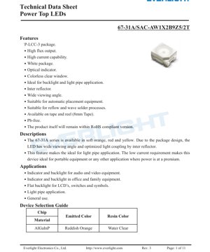
The 67-31A series represents a family of high-performance, surface-mount Power Top LEDs designed for indicator and backlight applications. These devices are housed in a compact P-LCC-3 (Plastic Leaded Chip Carrier) package, characterized by its white body and colorless clear window. The primary design goal is to provide a reliable, efficient light source suitable for automated assembly processes and demanding end-use environments.
The core advantages of this series include a high luminous intensity output, excellent current handling capability, and a very wide viewing angle facilitated by an integrated internal reflector. This reflector is key to optimizing light coupling, making these LEDs particularly ideal for use with light pipes, where efficient directional light transmission is critical. The low forward voltage requirement further enhances their suitability for battery-powered or power-sensitive portable equipment.
The target markets are broad, encompassing consumer electronics, office automation, industrial controls, and automotive interiors. Typical applications range from status indicators and switch backlighting in audio/video equipment to backlighting for LCD panels, symbols, and general-purpose illumination where a soft orange, red, or yellow light is desired.
2. Technical Parameter Deep Dive
2.1 Absolute Maximum Ratings
These ratings define the stress limits beyond which permanent damage to the device may occur. Operation under or at these limits is not guaranteed. Key parameters include a maximum reverse voltage (VR) of 5V, a continuous forward current (IF) of 50mA, and a peak forward current (IFP) of 100mA under pulsed conditions (1/10 duty cycle at 1kHz). The maximum power dissipation (Pd) is 120mW. The device is rated for an operating temperature range (Topr) of -40°C to +85°C and can withstand soldering temperatures as per industry-standard reflow profiles (260°C for 10 seconds).
2.2 Electro-Optical Characteristics
These parameters are measured at a junction temperature (Tj) of 25°C and a forward current of 50mA, representing typical operating conditions.
- Luminous Intensity (Iv): Ranges from a minimum of 1120 mcd to a maximum of 2850 mcd, with a typical tolerance of ±11%. This high brightness is a key feature.
- Viewing Angle (2θ1/2): A very wide 120 degrees (typical). This is the full angle at which the luminous intensity is half of the peak intensity, indicating a broad, diffuse light pattern.
- Forward Voltage (VF): Typically 2.35V, with a range from 1.95V to 2.75V at 50mA. The low VF contributes to higher efficiency.
- Wavelength: The dominant wavelength (λd) spans from 605.5 nm to 625.5 nm, placing the emitted color in the soft orange to red-orange region. The peak wavelength (λp) is typically 621 nm.
- Spectral Bandwidth (Δλ): Approximately 18 nm (typical), indicating a relatively narrow spectral emission centered around the peak wavelength.
3. Binning System Explanation
To ensure consistency in production, LEDs are sorted into performance bins. The 67-31A series uses a three-dimensional binning system.
3.1 Luminous Intensity Binning (CAT)
LEDs are grouped into four bins (W1, W2, X1, X2) based on their measured luminous intensity at 50mA. For example, bin W1 covers 1120-1420 mcd, while bin X2 covers 2250-2850 mcd. This allows designers to select a brightness grade suitable for their application.
3.2 Dominant Wavelength Binning (HUE)
Color consistency is controlled through dominant wavelength bins grouped under 'A'. Bins E1 through E5 cover the range from 605.5 nm to 625.5 nm in ~4 nm steps. This ensures the emitted color (soft orange) is uniform within a tight tolerance (±1nm).
3.3 Forward Voltage Binning (REF)
Forward voltage is binned in Group 'B9'. Bins 1 through 4 categorize VF from 1.95-2.15V up to 2.55-2.75V at 50mA. Matching VF bins can be important for current balancing in multi-LED circuits.
4. Performance Curve Analysis
The datasheet provides several characteristic curves that illustrate device behavior under varying conditions.
4.1 Relative Luminous Intensity vs. Forward Current
This curve shows that light output increases with forward current, but the relationship is not perfectly linear, especially at higher currents. It is crucial for determining the drive current needed to achieve a specific brightness.
4.2 Relative Luminous Intensity vs. Ambient Temperature
The luminous intensity of AlGaInP LEDs typically decreases as the ambient (and thus junction) temperature rises. This curve quantifies that derating, showing output dropping significantly as temperature increases from 25°C to 100°C. Proper thermal management is essential to maintain consistent brightness.
4.3 Forward Current vs. Forward Voltage
This IV curve depicts the exponential relationship between current and voltage. The typical VF of ~2.35V at 50mA is visible here. The curve is vital for designing the current-limiting circuitry.
4.4 Radiation Pattern
A polar diagram visually confirms the wide 120-degree viewing angle. The intensity distribution is roughly Lambertian, meaning it appears uniformly bright over a wide area when viewed directly, which is ideal for indicator applications.
4.5 Spectrum Distribution
The graph shows a single, narrow emission peak centered around 621 nm, characteristic of AlGaInP material, with no significant secondary peaks, ensuring color purity.
5. Mechanical and Packaging Information
5.1 Package Dimensions
The P-LCC-3 package has compact dimensions of approximately 2.0mm in length, 1.25mm in width, and 1.1mm in height (excluding the leads). Detailed drawings with tolerances (±0.1mm typically) are provided for PCB footprint design. The package features two anode leads and one common cathode lead for mechanical stability and solder joint reliability.
5.2 Polarity Identification
The cathode is typically identified by a green marking on the package or a notch/chamfer on one side. Correct orientation is essential during assembly to prevent reverse bias damage.
6. Soldering and Assembly Guidelines
The device is fully compatible with both reflow and wave soldering processes, making it suitable for high-volume automated manufacturing.
- Reflow Soldering: A maximum peak temperature of 260°C for 10 seconds is specified. Standard lead-free (Pb-free) reflow profiles are applicable.
- Hand Soldering: If necessary, a soldering iron tip temperature should not exceed 350°C, and contact time should be limited to 3 seconds per lead to prevent thermal damage to the plastic package.
- Storage Conditions: LEDs are moisture-sensitive (MSL). They are shipped in moisture-barrier bags with desiccant. Once opened, they should be used within a specified time frame or baked according to standard IPC/JEDEC guidelines before reflow to prevent "popcorn" cracking.
7. Packaging and Ordering Information
7.1 Tape and Reel Specifications
The components are supplied on 8mm carrier tape, wound onto standard 180mm reels. Each reel contains 2000 pieces. Detailed dimensions for the carrier tape pockets and reel are provided to ensure compatibility with automated pick-and-place equipment.
7.2 Label Explanation
The reel label contains critical information for traceability and verification: Part Number (PN), Customer Part Number (CPN), quantity (QTY), lot number (LOT NO), and the three key bin codes for Luminous Intensity (CAT), Dominant Wavelength (HUE), and Forward Voltage (REF).
8. Application Suggestions
8.1 Typical Application Scenarios
- Light Pipe Systems: The wide viewing angle and integrated reflector make this LED optimal for coupling light into acrylic or polycarbonate light guides, commonly used for illuminating buttons, symbols, or panel indicators from a remote source.
- LCD Backlighting: Suitable for edge-lighting small LCD displays or providing localized backlighting for icons.
- General Status Indicators: Power, connectivity, or operational status indicators in consumer, industrial, and automotive electronics.
8.2 Design Considerations
- Current Limiting: Always use a series resistor or constant-current driver to set the forward current. Do not connect directly to a voltage source. Calculate the resistor value using R = (Vsupply - VF) / IF.
- Thermal Management: While the package has low thermal resistance, ensure adequate PCB copper area (thermal pads) if operating at high ambient temperatures or near maximum current to manage junction temperature and maintain light output and longevity.
- ESD Protection: Although rated for 2000V (HBM), standard ESD handling precautions should be observed during assembly.
9. Technical Comparison and Differentiation
The 67-31A series differentiates itself through its specific combination of attributes. Compared to standard 0603 or 0805 chip LEDs, it offers significantly higher luminous intensity. Versus other high-power LEDs, it maintains a very low forward voltage and current requirement. The key differentiator is the integrated inter-reflector within the P-LCC-3 package, which is engineered to maximize light extraction and direct it upwards with a wide, uniform pattern. This built-in optical feature reduces the need for secondary optics in light pipe applications, simplifying design and potentially lowering system cost.
10. Frequently Asked Questions (Based on Technical Parameters)
10.1 What is the difference between peak wavelength and dominant wavelength?
Peak wavelength (λp) is the wavelength at which the spectral power distribution is maximum. Dominant wavelength (λd) is the single wavelength of monochromatic light that matches the perceived color of the LED. For color definition and binning, dominant wavelength is more relevant to human vision.
10.2 Can I drive this LED with a 3.3V supply?
Yes, but a current-limiting resistor is mandatory. With a typical VF of 2.35V at 50mA, the voltage drop across the resistor would be 3.3V - 2.35V = 0.95V. Using Ohm's Law, R = 0.95V / 0.05A = 19Ω. A standard 20Ω resistor would set the current close to 50mA.
10.3 How does temperature affect performance?
As shown in the performance curves, luminous intensity decreases with increasing junction temperature. Forward voltage also decreases slightly with temperature. For consistent brightness, avoid operating at high ambient temperatures or at the maximum current without thermal design considerations.
11. Practical Design and Usage Case
Case: Designing a Multi-Button Backlight for a Medical Device Panel
A designer needs to backlight six soft-touch buttons on a handheld medical instrument. Space is limited, and power consumption is critical as the device is battery-operated. The buttons are made of translucent silicone and use individual light pipes to channel light from remotely mounted LEDs on the main PCB.
Solution: The 67-31A series LEDs are selected. Their high intensity ensures sufficient light reaches the button surface through the light pipe. The wide 120-degree viewing angle efficiently couples light into the pipe's entry point. The low VF and 50mA operating current (which can be reduced to 20mA for lower brightness, saving power) are ideal for the battery-powered system. The LEDs are placed on the PCB under the light pipe mounts. A single current-limiting resistor is calculated for a series string of two LEDs (if Vsupply is 5V) or individual resistors for parallel connection, driven by a GPIO pin on the microcontroller for on/off/dimming control. The P-LCC-3 package is compatible with the automated assembly line used for the PCB.
12. Principle Introduction
The 67-31A LED is based on AlGaInP (Aluminum Gallium Indium Phosphide) semiconductor material. When a forward voltage is applied across the p-n junction, electrons and holes are injected into the active region where they recombine. In AlGaInP, this recombination process primarily releases energy in the form of photons (light) in the red to yellow-orange wavelength range (approximately 605-630 nm). The specific color (dominant wavelength) is determined by the precise composition of the AlGaInP layers. The generated light is emitted from the chip, shaped and directed by the internal reflector and clear epoxy lens of the P-LCC-3 package to achieve the desired wide viewing angle.
13. Development Trends
The general trend for indicator and backlight LEDs like the 67-31A series continues towards higher efficiency (more lumens per watt), which allows for the same brightness at lower current, extending battery life. Package miniaturization remains a focus, enabling denser PCB layouts. There is also a drive towards tighter binning tolerances for both color and flux to ensure greater consistency in mass production, especially for applications requiring uniform appearance across multiple units. Furthermore, enhanced reliability under higher temperature and humidity conditions is an ongoing area of development to meet the demands of automotive and industrial markets. The integration of more sophisticated internal optics, like the reflector in this series, to improve light extraction and control without external components is a key design trend.
LED Specification Terminology
Complete explanation of LED technical terms
Photoelectric Performance
| Term | Unit/Representation | Simple Explanation | Why Important |
|---|---|---|---|
| Luminous Efficacy | lm/W (lumens per watt) | Light output per watt of electricity, higher means more energy efficient. | Directly determines energy efficiency grade and electricity cost. |
| Luminous Flux | lm (lumens) | Total light emitted by source, commonly called "brightness". | Determines if the light is bright enough. |
| Viewing Angle | ° (degrees), e.g., 120° | Angle where light intensity drops to half, determines beam width. | Affects illumination range and uniformity. |
| CCT (Color Temperature) | K (Kelvin), e.g., 2700K/6500K | Warmth/coolness of light, lower values yellowish/warm, higher whitish/cool. | Determines lighting atmosphere and suitable scenarios. |
| CRI / Ra | Unitless, 0–100 | Ability to render object colors accurately, Ra≥80 is good. | Affects color authenticity, used in high-demand places like malls, museums. |
| SDCM | MacAdam ellipse steps, e.g., "5-step" | Color consistency metric, smaller steps mean more consistent color. | Ensures uniform color across same batch of LEDs. |
| Dominant Wavelength | nm (nanometers), e.g., 620nm (red) | Wavelength corresponding to color of colored LEDs. | Determines hue of red, yellow, green monochrome LEDs. |
| Spectral Distribution | Wavelength vs intensity curve | Shows intensity distribution across wavelengths. | Affects color rendering and quality. |
Electrical Parameters
| Term | Symbol | Simple Explanation | Design Considerations |
|---|---|---|---|
| Forward Voltage | Vf | Minimum voltage to turn on LED, like "starting threshold". | Driver voltage must be ≥Vf, voltages add up for series LEDs. |
| Forward Current | If | Current value for normal LED operation. | Usually constant current drive, current determines brightness & lifespan. |
| Max Pulse Current | Ifp | Peak current tolerable for short periods, used for dimming or flashing. | Pulse width & duty cycle must be strictly controlled to avoid damage. |
| Reverse Voltage | Vr | Max reverse voltage LED can withstand, beyond may cause breakdown. | Circuit must prevent reverse connection or voltage spikes. |
| Thermal Resistance | Rth (°C/W) | Resistance to heat transfer from chip to solder, lower is better. | High thermal resistance requires stronger heat dissipation. |
| ESD Immunity | V (HBM), e.g., 1000V | Ability to withstand electrostatic discharge, higher means less vulnerable. | Anti-static measures needed in production, especially for sensitive LEDs. |
Thermal Management & Reliability
| Term | Key Metric | Simple Explanation | Impact |
|---|---|---|---|
| Junction Temperature | Tj (°C) | Actual operating temperature inside LED chip. | Every 10°C reduction may double lifespan; too high causes light decay, color shift. |
| Lumen Depreciation | L70 / L80 (hours) | Time for brightness to drop to 70% or 80% of initial. | Directly defines LED "service life". |
| Lumen Maintenance | % (e.g., 70%) | Percentage of brightness retained after time. | Indicates brightness retention over long-term use. |
| Color Shift | Δu′v′ or MacAdam ellipse | Degree of color change during use. | Affects color consistency in lighting scenes. |
| Thermal Aging | Material degradation | Deterioration due to long-term high temperature. | May cause brightness drop, color change, or open-circuit failure. |
Packaging & Materials
| Term | Common Types | Simple Explanation | Features & Applications |
|---|---|---|---|
| Package Type | EMC, PPA, Ceramic | Housing material protecting chip, providing optical/thermal interface. | EMC: good heat resistance, low cost; Ceramic: better heat dissipation, longer life. |
| Chip Structure | Front, Flip Chip | Chip electrode arrangement. | Flip chip: better heat dissipation, higher efficacy, for high-power. |
| Phosphor Coating | YAG, Silicate, Nitride | Covers blue chip, converts some to yellow/red, mixes to white. | Different phosphors affect efficacy, CCT, and CRI. |
| Lens/Optics | Flat, Microlens, TIR | Optical structure on surface controlling light distribution. | Determines viewing angle and light distribution curve. |
Quality Control & Binning
| Term | Binning Content | Simple Explanation | Purpose |
|---|---|---|---|
| Luminous Flux Bin | Code e.g., 2G, 2H | Grouped by brightness, each group has min/max lumen values. | Ensures uniform brightness in same batch. |
| Voltage Bin | Code e.g., 6W, 6X | Grouped by forward voltage range. | Facilitates driver matching, improves system efficiency. |
| Color Bin | 5-step MacAdam ellipse | Grouped by color coordinates, ensuring tight range. | Guarantees color consistency, avoids uneven color within fixture. |
| CCT Bin | 2700K, 3000K etc. | Grouped by CCT, each has corresponding coordinate range. | Meets different scene CCT requirements. |
Testing & Certification
| Term | Standard/Test | Simple Explanation | Significance |
|---|---|---|---|
| LM-80 | Lumen maintenance test | Long-term lighting at constant temperature, recording brightness decay. | Used to estimate LED life (with TM-21). |
| TM-21 | Life estimation standard | Estimates life under actual conditions based on LM-80 data. | Provides scientific life prediction. |
| IESNA | Illuminating Engineering Society | Covers optical, electrical, thermal test methods. | Industry-recognized test basis. |
| RoHS / REACH | Environmental certification | Ensures no harmful substances (lead, mercury). | Market access requirement internationally. |
| ENERGY STAR / DLC | Energy efficiency certification | Energy efficiency and performance certification for lighting. | Used in government procurement, subsidy programs, enhances competitiveness. |