1. Product Overview
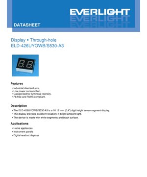
The ELD-426UYOWB/S530-A3 is a through-hole mounted, seven-segment alphanumeric display designed for clear digital readouts. It features a standard industrial size with a digit height of 10.16 mm (0.4 inches), making it suitable for applications where medium-sized numeric or limited alphanumeric information needs to be presented. The device is constructed with white light-emitting segments against a black background surface, which provides high contrast and excellent readability even in brightly lit ambient conditions. This design choice minimizes glare and enhances the user's ability to discern the illuminated characters.
The core technology utilizes AlGaInP (Aluminum Gallium Indium Phosphide) semiconductor material for the light-emitting chips. This material is efficient at producing light in the orange-red spectrum. The emitted orange light, with a dominant wavelength of 605 nm, offers good visibility and is often chosen for indicator panels and instrumentation. The resin used for encapsulation is a white diffusive type, which helps to evenly scatter the light from the individual LED segments, creating a uniform and consistent appearance across all parts of the character.
1.1 Key Features and Advantages
The display offers several key advantages for designers and manufacturers. Its primary feature is low power consumption, which is critical for battery-operated devices or systems where energy efficiency is a priority. The components are categorized (binned) for luminous intensity. This means displays are sorted and labeled according to their measured light output, allowing for consistency in brightness across multiple units in a single product, which is essential for multi-digit displays or panels using several such components.
The device is compliant with Pb-free and RoHS (Restriction of Hazardous Substances) directives, making it suitable for use in products sold in markets with strict environmental regulations. Its through-hole design provides robust mechanical connections, making it reliable for applications subject to vibration or physical stress. The industrial standard footprint ensures it is compatible with common PCB layouts and automated insertion equipment.
1.2 Target Applications and Market
This seven-segment display is targeted at a wide range of electronic applications that require a reliable and clear numeric interface. Its primary application domains include home appliances, such as ovens, microwaves, washing machines, and air conditioners, where it can display settings, timers, or status codes. It is equally suited for instrument panels in industrial equipment, automotive dashboards (for secondary displays), and test and measurement devices.
Another significant application is in digital readout displays for scales, counters, timers, and simple control panels. The orange color is often preferred in environments where the display needs to be easily distinguishable or where it serves as a warning or status indicator. The robustness and standard size make it a versatile choice for both consumer and industrial electronic products.
2. Technical Parameters and Specifications
A detailed understanding of the device's limits and operating characteristics is crucial for reliable circuit design and long-term performance.
2.1 Absolute Maximum Ratings
The Absolute Maximum Ratings define the stress limits beyond which permanent damage to the device may occur. These ratings must never be exceeded, even momentarily, during operation or handling. For the ELD-426UYOWB/S530-A3, the maximum reverse voltage (VR) is 5V. Applying a higher reverse voltage can break down the LED junction. The maximum continuous forward current (IF) is 25 mA. Exceeding this current will generate excessive heat, degrading the LED's internal structure and shortening its lifespan.
For pulsed operation, a higher peak forward current (IFP) of 60 mA is allowed, but only under specific conditions: a duty cycle of 1/10 (10%) and a frequency of 1 kHz. This allows for brief periods of higher brightness. The maximum power dissipation (Pd) is 60 mW, calculated as the product of forward voltage and current. The device is rated for operation (Topr) between -40°C and +85°C, making it suitable for harsh environments. Storage temperature (Tstg) can range from -40°C to +100°C. The soldering temperature (Tsol) must not exceed 260°C, and the soldering iron contact time should be 5 seconds or less to prevent thermal damage to the plastic package and internal bonds.
2.2 Electro-Optical Characteristics
These characteristics are measured under standard test conditions (Ta=25°C) and represent the typical performance of the device. The luminous intensity (Iv) has a typical value of 12.5 mcd when driven at a forward current (IF) of 10 mA, with a minimum specified value of 5.6 mcd. It is important to note that the datasheet specifies this is an average value measured on one 7-segment. The tolerance for luminous intensity is ±10%.
The spectral characteristics define the color of the emitted light. The peak wavelength (λp) is typically 611 nm, while the dominant wavelength (λd), which correlates more closely with perceived color, is typically 605 nm (orange). The spectral radiation bandwidth (Δλ) is typically 17 nm, indicating the spread of wavelengths emitted. The forward voltage (VF) is typically 2.0V with a maximum of 2.4V at IF=20mA, with a tolerance of ±0.1V. The reverse current (IR) is very low, with a maximum of 100 µA at VR=5V.
3. Performance Curve Analysis
Graphical data provides deeper insight into the device's behavior under varying conditions.
3.1 Spectrum Distribution
The spectrum distribution curve (relative luminous intensity vs. wavelength) would show a single peak centered around 611 nm (typical) with a width of approximately 17 nm at half the maximum intensity (FWHM). This confirms the monochromatic orange output of the AlGaInP material. There should be no significant secondary peaks, indicating pure color emission. The shape of this curve is important for applications where color consistency or specific wavelength filtering is involved.
3.2 Forward Current vs. Forward Voltage
The I-V curve illustrates the diode characteristics of the LED segments. It is non-linear. At very low currents, the voltage is minimal. As current increases, the forward voltage rises sharply and then increases more gradually in the typical operating range (around 2.0V at 20 mA). This curve is essential for designing the current-limiting circuitry. A small change in driving voltage can lead to a large change in current, which is why LEDs are typically driven with constant current sources or circuits with appropriate series resistors.
3.3 Forward Current Derating Curve
This is one of the most critical curves for reliability. It shows the maximum allowable continuous forward current as a function of the ambient temperature. At 25°C, the full 25 mA is permitted. As the ambient temperature increases, the maximum allowed current must be reduced linearly. This is because the LED's internal junction temperature rises with both ambient heat and self-heating from the current. Exceeding the safe junction temperature drastically reduces luminous output and lifespan. The curve typically shows the current dropping to zero at the maximum junction temperature, which is linked to the maximum operating ambient temperature of 85°C. Designers must ensure the operating point (ambient temperature + driving current) falls within the safe area defined by this curve.
4. Mechanical and Package Information
4.1 Package Dimensions
The mechanical drawing provides the exact physical dimensions of the display. Key measurements include the overall height, width, and depth of the package, the spacing between the pins, the diameter and position of the pins, and the size and location of the digit window. The drawing specifies that tolerances are ±0.25 mm unless otherwise noted. All dimensions are in millimeters (mm). This information is vital for PCB layout (footprint design), ensuring proper fit within the product enclosure, and for automated assembly processes.
4.2 Pinout and Internal Circuit Diagram
The internal circuit diagram shows the electrical connection of the individual LED segments (a, b, c, d, e, f, g, and often a decimal point DP) to the external pins. For a common-cathode or common-anode configuration, it indicates which pin is the common connection. This diagram is essential for correctly wiring the display to the driver circuit (e.g., a microcontroller or decoder IC). Connecting the common pin incorrectly will prevent the display from lighting up.
5. Assembly and Handling Guidelines
5.1 Soldering Recommendations
The datasheet specifies a maximum soldering temperature of 260°C with a contact time of 5 seconds or less. This applies to both hand soldering and wave soldering processes. Prolonged exposure to high temperature can melt the plastic package, damage the internal wire bonds, or degrade the LED chip. It is recommended to use a temperature-controlled soldering iron and to allow adequate cooling time between soldering multiple pins. For wave soldering, the profile (preheat, soak, peak temperature, cooling) should be controlled to stay within these limits.
5.2 Electrostatic Discharge (ESD) Protection
LEDs are semiconductor devices and are sensitive to electrostatic discharge. ESD can cause immediate failure or latent damage that reduces long-term reliability. The datasheet strongly recommends several anti-ESD measures during handling and assembly: Operators should wear grounded wrist straps and work on ESD-safe mats. Workstations, tools, and equipment should be properly grounded. The use of ionizers is recommended to neutralize static charges on non-conductive materials. The driving circuit should also include protection against voltage surges that might occur during operation.
5.3 Electrical Operation Precautions
The LEDs must be operated in forward bias. The driving circuit must be designed to ensure that no significant reverse voltage is applied across the LED segments, even when they are supposed to be off. Continuous application of reverse voltage, even below the 5V absolute maximum, can cause electromigration within the semiconductor material, leading to increased leakage current and eventual failure. This is often addressed in circuit design by ensuring the driver IC or transistor can only apply a forward voltage or a very small reverse voltage when off.
6. Packaging and Ordering Information
6.1 Packing Specifications
The device is packed in tubes for automated handling. The standard packing process is: 25 pieces per tube, 64 tubes per box, and 4 boxes per master carton. This totals 6,400 pieces per carton. The tube packaging protects the pins from bending and the display face from scratches during transportation and storage.
6.2 Label Explanation
The packaging labels contain several codes for identification and traceability. Key fields include: CPN (Customer's Part Number), P/N (Manufacturer's Part Number: ELD-426UYOWB/S530-A3), QTY (Packing Quantity), CAT (Luminous Intensity Rank/Category), and LOT No (Lot Number for traceability). Understanding these labels is important for inventory management, quality control, and ensuring the correct component is used in production.
7. Application Design Considerations
7.1 Current Limiting and Driving
The most common method for driving a single-digit 7-segment display like this is to use a series resistor for each segment (or a single resistor on the common pin for multiplexed designs). The resistor value is calculated using Ohm's Law: R = (Vsupply - VF) / IF. For example, with a 5V supply, a typical VF of 2.0V, and a desired IF of 10 mA, the resistor would be (5 - 2.0) / 0.01 = 300 Ohms. A 330 Ohm resistor would be a standard choice. For multi-digit multiplexing, a driver IC (like a 74HC595 shift register or a dedicated LED driver) is used to control the segments and digit selection rapidly, reducing the number of required microcontroller pins.
7.2 Thermal Management
While this is a low-power device, thermal considerations are still important for longevity, especially in high ambient temperature applications or when driving near the maximum current. Ensuring adequate airflow around the display on the PCB can help. The PCB itself can act as a heat sink for the pins. For critical applications, refer to the forward current derating curve and operate the LED at a lower current if the ambient temperature is high.
7.3 Optical Considerations
The black background provides high contrast. When designing the front panel or lens that covers the display, consider materials and coatings that minimize reflection and glare to maintain readability. The viewing angle of the display (implied by the diffusive resin) is typically wide, but this should be verified if off-axis viewing is critical. The orange color may be filtered or appear differently behind colored filters or tinted glass, so testing in the final assembly is recommended.
8. Technical Comparison and Selection
When selecting a seven-segment display, key differentiators include digit height, color, brightness (luminous intensity), forward voltage, power consumption, and package type (through-hole vs. SMD). The ELD-426UYOWB/S530-A3's primary advantages are its standard 0.4\" size, orange color for high visibility, categorized luminous intensity for consistency, and robust through-hole construction. Compared to smaller SMD displays, it is easier to prototype with and may be more suitable for applications requiring higher durability. Compared to other colors, orange often has a higher perceived brightness at lower current levels than red or green in some semiconductor materials, and it can be more visible in certain lighting conditions.
9. Frequently Asked Questions (FAQ)
9.1 What is the purpose of the luminous intensity categorization (CAT)?
Categorization ensures brightness uniformity. Displays from the same CAT code will have similar light output. This is crucial when using multiple displays side-by-side (e.g., a 4-digit clock) to avoid noticeable brightness differences between digits, which would look unprofessional.
9.2 Can I drive this display directly from a microcontroller pin?
It is not recommended to drive an LED segment directly from a standard microcontroller GPIO pin. The typical GPIO pin can only source or sink 20-25 mA, which is the absolute maximum for one segment. Driving one segment at max current leaves no headroom and risks damaging the microcontroller if multiple segments are accidentally turned on. Furthermore, the total current for a fully lit digit (all 7 segments) would far exceed a microcontroller's capabilities. Always use a series resistor and/or a driver IC (transistor, buffer, dedicated LED driver).
9.3 What does \"Pb free and RoHS compliant\" mean?
This means the device is manufactured without the use of lead (Pb) in its solder plating or other materials, and it complies with the European Union's Restriction of Hazardous Substances directive. This makes the component suitable for use in products sold in most global markets, which have adopted similar environmental regulations.
9.4 How do I determine the common pin (anode or cathode)?
The internal circuit diagram in the datasheet's package dimension section will clearly show the pinout. It will indicate which pin is connected to all the anodes (common anode) or all the cathodes (common cathode) of the segment LEDs. You must know this to design your driving circuit correctly. If the diagram is not available, a simple test with a current-limited power supply (e.g., 3V with a 1k resistor in series) can be used to probe pin pairs.
LED Specification Terminology
Complete explanation of LED technical terms
Photoelectric Performance
| Term | Unit/Representation | Simple Explanation | Why Important |
|---|---|---|---|
| Luminous Efficacy | lm/W (lumens per watt) | Light output per watt of electricity, higher means more energy efficient. | Directly determines energy efficiency grade and electricity cost. |
| Luminous Flux | lm (lumens) | Total light emitted by source, commonly called "brightness". | Determines if the light is bright enough. |
| Viewing Angle | ° (degrees), e.g., 120° | Angle where light intensity drops to half, determines beam width. | Affects illumination range and uniformity. |
| CCT (Color Temperature) | K (Kelvin), e.g., 2700K/6500K | Warmth/coolness of light, lower values yellowish/warm, higher whitish/cool. | Determines lighting atmosphere and suitable scenarios. |
| CRI / Ra | Unitless, 0–100 | Ability to render object colors accurately, Ra≥80 is good. | Affects color authenticity, used in high-demand places like malls, museums. |
| SDCM | MacAdam ellipse steps, e.g., "5-step" | Color consistency metric, smaller steps mean more consistent color. | Ensures uniform color across same batch of LEDs. |
| Dominant Wavelength | nm (nanometers), e.g., 620nm (red) | Wavelength corresponding to color of colored LEDs. | Determines hue of red, yellow, green monochrome LEDs. |
| Spectral Distribution | Wavelength vs intensity curve | Shows intensity distribution across wavelengths. | Affects color rendering and quality. |
Electrical Parameters
| Term | Symbol | Simple Explanation | Design Considerations |
|---|---|---|---|
| Forward Voltage | Vf | Minimum voltage to turn on LED, like "starting threshold". | Driver voltage must be ≥Vf, voltages add up for series LEDs. |
| Forward Current | If | Current value for normal LED operation. | Usually constant current drive, current determines brightness & lifespan. |
| Max Pulse Current | Ifp | Peak current tolerable for short periods, used for dimming or flashing. | Pulse width & duty cycle must be strictly controlled to avoid damage. |
| Reverse Voltage | Vr | Max reverse voltage LED can withstand, beyond may cause breakdown. | Circuit must prevent reverse connection or voltage spikes. |
| Thermal Resistance | Rth (°C/W) | Resistance to heat transfer from chip to solder, lower is better. | High thermal resistance requires stronger heat dissipation. |
| ESD Immunity | V (HBM), e.g., 1000V | Ability to withstand electrostatic discharge, higher means less vulnerable. | Anti-static measures needed in production, especially for sensitive LEDs. |
Thermal Management & Reliability
| Term | Key Metric | Simple Explanation | Impact |
|---|---|---|---|
| Junction Temperature | Tj (°C) | Actual operating temperature inside LED chip. | Every 10°C reduction may double lifespan; too high causes light decay, color shift. |
| Lumen Depreciation | L70 / L80 (hours) | Time for brightness to drop to 70% or 80% of initial. | Directly defines LED "service life". |
| Lumen Maintenance | % (e.g., 70%) | Percentage of brightness retained after time. | Indicates brightness retention over long-term use. |
| Color Shift | Δu′v′ or MacAdam ellipse | Degree of color change during use. | Affects color consistency in lighting scenes. |
| Thermal Aging | Material degradation | Deterioration due to long-term high temperature. | May cause brightness drop, color change, or open-circuit failure. |
Packaging & Materials
| Term | Common Types | Simple Explanation | Features & Applications |
|---|---|---|---|
| Package Type | EMC, PPA, Ceramic | Housing material protecting chip, providing optical/thermal interface. | EMC: good heat resistance, low cost; Ceramic: better heat dissipation, longer life. |
| Chip Structure | Front, Flip Chip | Chip electrode arrangement. | Flip chip: better heat dissipation, higher efficacy, for high-power. |
| Phosphor Coating | YAG, Silicate, Nitride | Covers blue chip, converts some to yellow/red, mixes to white. | Different phosphors affect efficacy, CCT, and CRI. |
| Lens/Optics | Flat, Microlens, TIR | Optical structure on surface controlling light distribution. | Determines viewing angle and light distribution curve. |
Quality Control & Binning
| Term | Binning Content | Simple Explanation | Purpose |
|---|---|---|---|
| Luminous Flux Bin | Code e.g., 2G, 2H | Grouped by brightness, each group has min/max lumen values. | Ensures uniform brightness in same batch. |
| Voltage Bin | Code e.g., 6W, 6X | Grouped by forward voltage range. | Facilitates driver matching, improves system efficiency. |
| Color Bin | 5-step MacAdam ellipse | Grouped by color coordinates, ensuring tight range. | Guarantees color consistency, avoids uneven color within fixture. |
| CCT Bin | 2700K, 3000K etc. | Grouped by CCT, each has corresponding coordinate range. | Meets different scene CCT requirements. |
Testing & Certification
| Term | Standard/Test | Simple Explanation | Significance |
|---|---|---|---|
| LM-80 | Lumen maintenance test | Long-term lighting at constant temperature, recording brightness decay. | Used to estimate LED life (with TM-21). |
| TM-21 | Life estimation standard | Estimates life under actual conditions based on LM-80 data. | Provides scientific life prediction. |
| IESNA | Illuminating Engineering Society | Covers optical, electrical, thermal test methods. | Industry-recognized test basis. |
| RoHS / REACH | Environmental certification | Ensures no harmful substances (lead, mercury). | Market access requirement internationally. |
| ENERGY STAR / DLC | Energy efficiency certification | Energy efficiency and performance certification for lighting. | Used in government procurement, subsidy programs, enhances competitiveness. |