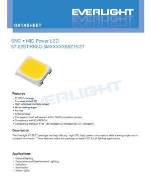
1. Product Overview
The 67-22ST is a surface-mount device (SMD) high-power LED designed for demanding lighting applications. It utilizes a PLCC-2 (Plastic Leaded Chip Carrier) package, which offers a compact form factor suitable for automated assembly processes. The primary emitted color is white, available in various correlated color temperatures (CCT) ranging from warm white (2700K) to cool white (6500K). Its core advantages include high luminous efficacy, excellent color rendering with a minimum Color Rendering Index (CRI) of 80, a wide viewing angle of 120 degrees, and robust construction compliant with major environmental and safety standards such as RoHS, EU REACH, and halogen-free requirements.
The device is engineered for general lighting, decorative lighting, entertainment lighting, indicator applications, and switch illumination. Its combination of high light output, good color quality, and reliable performance makes it a versatile component for both consumer and professional lighting products.
2. Technical Parameter Deep Dive
2.1 Absolute Maximum Ratings
The device must not be operated beyond these limits to prevent permanent damage. The maximum continuous forward current (IF) is 180 mA, with a peak forward current (IFP) of 300 mA permissible under pulsed conditions (duty cycle 1/10, pulse width 10ms). The maximum power dissipation (Pd) is 1020 mW. The operational ambient temperature range is from -40°C to +85°C, while storage can be from -40°C to +100°C. The thermal resistance from the junction to the soldering point (Rth J-S) is 17 °C/W, which is critical for thermal management design. The maximum allowable junction temperature (Tj) is 115°C. Soldering must adhere to specific profiles: reflow soldering at 260°C for a maximum of 10 seconds, or hand soldering at 350°C for a maximum of 3 seconds.
2.2 Electro-Optical Characteristics
These parameters are specified at a standard test condition of a soldering point temperature (TSoldering) of 25°C and a forward current (IF) of 150 mA. The luminous flux (Φ) has a minimum value starting from 120 lumens, depending on the specific product bin (see section 3). The forward voltage (VF) typically ranges from 5.8V to a maximum of 6.8V. The Color Rendering Index (Ra or CRI) has a minimum value of 80, with a tolerance of ±2. It is important to note the R9 value (saturated red) is specified as 0, which is typical for many white LEDs and indicates a potential weakness in rendering deep red colors. The viewing angle (2θ1/2) is 120 degrees, providing a broad, even light distribution. The reverse current (IR) is a maximum of 50 µA at a reverse voltage (VR) of 10V.
3. Binning System Explanation
3.1 Product Numbering and Binning Codes
The product number follows a specific structure: 67-22ST/KK8C-5MXX XXX XXZ15/2T. Key segments within this code define critical parameters. The characters following '5M' indicate the CRI, CCT, and luminous flux bin. For example, in '5M40140', '40' represents a CCT of 4000K, and '140' represents a minimum luminous flux of 140 lumens. The '68' denotes the maximum forward voltage bin (6.8V). 'Z15' specifies the operating forward current of 150mA. The '/2T' likely indicates the packaging type or reel quantity.
3.2 Color Rendering Index (CRI) Binning
The CRI is binned using single-letter codes with defined minimum values: M (60), N (65), L (70), Q (75), K (80), P (85), H (90). The products listed in this datasheet primarily use the 'K' bin, corresponding to a minimum CRI of 80, with a tolerance of ±2.
3.3 Luminous Flux Binning
Luminous flux is tightly binned to ensure consistency. The bins are organized into series based on a reference flux at 4000K (e.g., 135Lm, 140Lm, 145Lm, 155Lm). Each series contains multiple bin codes (e.g., 120L5, 125L5) that define a 5-lumen range. For instance, in the 140Lm series, the 140L5 bin has a minimum of 140 lm and a maximum of 145 lm at IF=150mA. The overall flux tolerance is ±11%.
3.4 Forward Voltage Binning
Forward voltage is grouped into bins with a 0.2V range. The bin codes are 58B (5.8-6.0V), 60B (6.0-6.2V), 62B (6.2-6.4V), 64B (6.4-6.6V), and 66B (6.6-6.8V). The tolerance for forward voltage is ±0.1V. The '68' in the part number indicates the maximum voltage for that grouping is 6.8V.
3.5 Correlated Color Temperature (CCT) and MacAdam Ellipse
The CCT is specified in Kelvin (K) with standard values: 2700K, 3000K, 3500K, 4000K, 5000K, 5700K, 6000K, and 6500K. The color consistency is controlled within a 5-step MacAdam ellipse. This means the chromaticity coordinates (Cx, Cy) of LEDs from the same bin will fall within an ellipse on the CIE chromaticity diagram that is 5 times the standard deviation of color matching, ensuring very tight color uniformity. An example coordinate for the 2700K, 5-step bin is given as Cx=0.4583, Cy=0.4104.
4. Mass Production List and Device Selection
The datasheet provides extensive lists of mass-produced part numbers, organized by their minimum luminous flux at 4000K. Each list includes variants for all the standard CCTs (2700K to 6500K). For example, the series targeting 140 lm at 4000K includes part numbers like 67-22ST/KK8C-5M4014068Z15/2T (4000K, 140 lm min) and 67-22ST/KK8C-5M6513568Z15/2T (6500K, 135 lm min). This allows designers to select the exact combination of color temperature and light output required for their application. The device selection guide confirms the chip material is InGaN, emitting white light (cool, neutral, warm) with a water-clear resin lens.
5. Application Suggestions and Design Considerations
5.1 Typical Application Scenarios
This LED is ideal for General Lighting: downlights, panel lights, bulb replacements where high efficacy and good CRI are needed. Decorative and Entertainment Lighting: accent lighting, architectural highlights, stage lighting benefiting from the wide viewing angle. Indicators and Illumination: status indicators, backlighting for panels or switches requiring a bright, uniform light source.
5.2 Design Considerations
Thermal Management: With a thermal resistance of 17 °C/W and a max Tj of 115°C, proper heat sinking is crucial. The soldering pad on the PCB must be designed to act as a heat spreader. Calculate the expected junction temperature based on drive current, ambient temperature, and PCB thermal performance. Electrical Drive: A constant current driver is recommended, set to 150mA or lower for optimal lifetime and performance. Ensure the driver can handle the forward voltage range (up to 6.8V). The peak current rating allows for brief overdrive in pulsed applications. Optical Design: The 120-degree viewing angle is intrinsic; secondary optics (lenses, reflectors) can be used to modify the beam pattern if needed. ESD Sensitivity: The product is sensitive to electrostatic discharge. Proper ESD handling procedures must be followed during assembly and installation.
6. Soldering and Assembly Guidelines
Adherence to the soldering specifications is vital for reliability. For reflow soldering, the peak temperature must not exceed 260°C, and the time above 260°C must be limited to 10 seconds. A standard lead-free reflow profile is suitable. For hand soldering, the iron tip temperature should not exceed 350°C, and contact time per lead should be limited to 3 seconds. Avoid applying mechanical stress to the LED body during or after soldering. Store components in a dry, anti-static environment before use. After soldering, allow the assembly to cool naturally; avoid rapid quenching.
7. Packaging and Ordering Information
The LEDs are supplied on tape and reel for automated pick-and-place assembly. The specific quantity per reel is implied by the '/2T' suffix in the part number, though the exact number should be confirmed with the supplier. The product number itself serves as the complete ordering code, specifying all key optical and electrical parameters (CRI, CCT, Flux, VF, IF). Always refer to the full part number from the mass production list when placing an order.
8. Technical Comparison and Differentiation
Compared to standard mid-power LEDs, the 67-22ST offers higher drive current (150mA vs. typical 60-150mA for 2835 LEDs) and consequently higher luminous flux output. Its PLCC-2 package is a common and robust form factor. The key differentiators are its explicitly defined, tight binning for flux, voltage, and color (5-step MacAdam), which is essential for applications requiring consistent color and brightness across multiple units. The specification of a minimum CRI of 80 (with some bins available up to 90) positions it for quality lighting applications, unlike LEDs focused solely on maximum efficacy. The compliance with halogen-free standards is an additional environmental benefit for certain market segments.
9. Frequently Asked Questions (Based on Technical Parameters)
Q: What is the actual power consumption of this LED?
A: Power (W) = Forward Current (A) x Forward Voltage (V). At the typical drive of 150mA (0.15A) and a typical VF of 6.3V, power is approximately 0.945W.
Q: Can I drive this LED at 180mA continuously?
A: While 180mA is the Absolute Maximum Rating, the recommended operating condition is 150mA. Operating at 180mA will increase junction temperature, reduce lifetime, and may cause accelerated lumen depreciation. It should only be considered if thermal management is exceptional and lifetime requirements are less stringent.
Q: The R9 value is 0. What does this mean for light quality?
A: An R9 value of 0 indicates the LED does not render saturated red tones well. Objects with deep red colors may appear dull or brownish. For applications where accurate red rendition is critical (e.g., retail lighting for meat or produce, art galleries), an LED with a positive R9 value (part of \"high CRI\" or \"full spectrum\" LEDs) would be more suitable.
Q: How do I interpret the luminous flux bin code '140L5'?
A: The '140' indicates the minimum luminous flux in lumens for that bin. The 'L5' likely denotes a 5-lumen bin width. Therefore, '140L5' means LEDs in this bin will have a flux between 140 lm (min) and 145 lm (max) under standard test conditions.
10. Practical Design Case Study
Scenario: Designing a 4-foot linear LED fixture for office lighting targeting 4000K color temperature and high uniformity.
Selection: Choose part number 67-22ST/KK8C-5M4014068Z15/2T. This ensures a minimum CRI of 80, CCT of 4000K, and a minimum flux of 140 lm per LED.
Thermal Design: The PCB should be metal-core (MCPCB) for effective heat dissipation. Calculate the required number of LEDs to achieve the target fixture lumens, then verify that the total heat load can be managed by the fixture's housing to keep the LED solder point temperature within a safe range (well below 85°C ambient).
Electrical Design: Use a constant current LED driver rated for the total voltage drop (Number of LEDs in series * Max VF) and set to deliver 150mA. Include appropriate protection against over-voltage and open/short circuits.
Optical/Mechanical: Space the LEDs evenly on the MCPCB. A diffuser cover will help blend the individual LED points into a uniform line of light, leveraging the native 120-degree beam angle.
11. Operating Principle Introduction
This LED is a solid-state light source based on semiconductor physics. It uses an Indium Gallium Nitride (InGaN) chip. When a forward voltage is applied, electrons and holes recombine within the semiconductor's active region, releasing energy in the form of photons (light). The specific composition of the InGaN layers determines the primary blue wavelength emitted. This blue light then strikes a phosphor coating (cerium-doped yttrium aluminum garnet or similar) inside the water-clear resin package. The phosphor absorbs a portion of the blue light and re-emits it across a broad spectrum of longer wavelengths (yellow, red). The mixture of the remaining blue light and the phosphor-converted light results in the perception of white light. The correlated color temperature (CCT) is adjusted by modifying the phosphor composition and concentration.
12. Technology Trends and Context
The 67-22ST represents a mature, high-reliability class of SMD high-power LEDs. Current trends in LED technology continue to focus on increasing luminous efficacy (lumens per watt), improving color rendering quality (especially R9 and Rf values), and enhancing reliability at higher operating temperatures and currents. There is also a strong drive towards miniaturization (smaller packages with equal or greater output) and integration (COB - Chip-on-Board, and integrated modules). Furthermore, smart lighting and human-centric lighting are pushing for LEDs with tunable CCT and dimming capabilities without color shift. While this specific product is a discrete component, understanding these trends helps in selecting the right technology for future-proof designs, where factors like connected lighting or circadian rhythm support might become requirements.
LED Specification Terminology
Complete explanation of LED technical terms
Photoelectric Performance
| Term | Unit/Representation | Simple Explanation | Why Important |
|---|---|---|---|
| Luminous Efficacy | lm/W (lumens per watt) | Light output per watt of electricity, higher means more energy efficient. | Directly determines energy efficiency grade and electricity cost. |
| Luminous Flux | lm (lumens) | Total light emitted by source, commonly called "brightness". | Determines if the light is bright enough. |
| Viewing Angle | ° (degrees), e.g., 120° | Angle where light intensity drops to half, determines beam width. | Affects illumination range and uniformity. |
| CCT (Color Temperature) | K (Kelvin), e.g., 2700K/6500K | Warmth/coolness of light, lower values yellowish/warm, higher whitish/cool. | Determines lighting atmosphere and suitable scenarios. |
| CRI / Ra | Unitless, 0–100 | Ability to render object colors accurately, Ra≥80 is good. | Affects color authenticity, used in high-demand places like malls, museums. |
| SDCM | MacAdam ellipse steps, e.g., "5-step" | Color consistency metric, smaller steps mean more consistent color. | Ensures uniform color across same batch of LEDs. |
| Dominant Wavelength | nm (nanometers), e.g., 620nm (red) | Wavelength corresponding to color of colored LEDs. | Determines hue of red, yellow, green monochrome LEDs. |
| Spectral Distribution | Wavelength vs intensity curve | Shows intensity distribution across wavelengths. | Affects color rendering and quality. |
Electrical Parameters
| Term | Symbol | Simple Explanation | Design Considerations |
|---|---|---|---|
| Forward Voltage | Vf | Minimum voltage to turn on LED, like "starting threshold". | Driver voltage must be ≥Vf, voltages add up for series LEDs. |
| Forward Current | If | Current value for normal LED operation. | Usually constant current drive, current determines brightness & lifespan. |
| Max Pulse Current | Ifp | Peak current tolerable for short periods, used for dimming or flashing. | Pulse width & duty cycle must be strictly controlled to avoid damage. |
| Reverse Voltage | Vr | Max reverse voltage LED can withstand, beyond may cause breakdown. | Circuit must prevent reverse connection or voltage spikes. |
| Thermal Resistance | Rth (°C/W) | Resistance to heat transfer from chip to solder, lower is better. | High thermal resistance requires stronger heat dissipation. |
| ESD Immunity | V (HBM), e.g., 1000V | Ability to withstand electrostatic discharge, higher means less vulnerable. | Anti-static measures needed in production, especially for sensitive LEDs. |
Thermal Management & Reliability
| Term | Key Metric | Simple Explanation | Impact |
|---|---|---|---|
| Junction Temperature | Tj (°C) | Actual operating temperature inside LED chip. | Every 10°C reduction may double lifespan; too high causes light decay, color shift. |
| Lumen Depreciation | L70 / L80 (hours) | Time for brightness to drop to 70% or 80% of initial. | Directly defines LED "service life". |
| Lumen Maintenance | % (e.g., 70%) | Percentage of brightness retained after time. | Indicates brightness retention over long-term use. |
| Color Shift | Δu′v′ or MacAdam ellipse | Degree of color change during use. | Affects color consistency in lighting scenes. |
| Thermal Aging | Material degradation | Deterioration due to long-term high temperature. | May cause brightness drop, color change, or open-circuit failure. |
Packaging & Materials
| Term | Common Types | Simple Explanation | Features & Applications |
|---|---|---|---|
| Package Type | EMC, PPA, Ceramic | Housing material protecting chip, providing optical/thermal interface. | EMC: good heat resistance, low cost; Ceramic: better heat dissipation, longer life. |
| Chip Structure | Front, Flip Chip | Chip electrode arrangement. | Flip chip: better heat dissipation, higher efficacy, for high-power. |
| Phosphor Coating | YAG, Silicate, Nitride | Covers blue chip, converts some to yellow/red, mixes to white. | Different phosphors affect efficacy, CCT, and CRI. |
| Lens/Optics | Flat, Microlens, TIR | Optical structure on surface controlling light distribution. | Determines viewing angle and light distribution curve. |
Quality Control & Binning
| Term | Binning Content | Simple Explanation | Purpose |
|---|---|---|---|
| Luminous Flux Bin | Code e.g., 2G, 2H | Grouped by brightness, each group has min/max lumen values. | Ensures uniform brightness in same batch. |
| Voltage Bin | Code e.g., 6W, 6X | Grouped by forward voltage range. | Facilitates driver matching, improves system efficiency. |
| Color Bin | 5-step MacAdam ellipse | Grouped by color coordinates, ensuring tight range. | Guarantees color consistency, avoids uneven color within fixture. |
| CCT Bin | 2700K, 3000K etc. | Grouped by CCT, each has corresponding coordinate range. | Meets different scene CCT requirements. |
Testing & Certification
| Term | Standard/Test | Simple Explanation | Significance |
|---|---|---|---|
| LM-80 | Lumen maintenance test | Long-term lighting at constant temperature, recording brightness decay. | Used to estimate LED life (with TM-21). |
| TM-21 | Life estimation standard | Estimates life under actual conditions based on LM-80 data. | Provides scientific life prediction. |
| IESNA | Illuminating Engineering Society | Covers optical, electrical, thermal test methods. | Industry-recognized test basis. |
| RoHS / REACH | Environmental certification | Ensures no harmful substances (lead, mercury). | Market access requirement internationally. |
| ENERGY STAR / DLC | Energy efficiency certification | Energy efficiency and performance certification for lighting. | Used in government procurement, subsidy programs, enhances competitiveness. |