Table of Contents
- 1. Product Overview
- 1.1 Core Advantages and Product Positioning
- 1.2 Target Market and Applications
- 2. In-Depth Technical Parameter Analysis
- 2.1 Absolute Maximum Ratings
- 2.2 Electro-Optical Characteristics
- 2.3 Thermal Characteristics and Derating
- 3. Binning System Explanation
- 3.1 Luminous Intensity Binning
- 3.2 Dominant Wavelength Binning
- 3.3 Forward Voltage Binning
- 4. Performance Curve Analysis
- 4.1 Relative Luminous Intensity vs. Forward Current
- 4.2 Relative Luminous Intensity vs. Ambient Temperature
- 4.3 Forward Voltage vs. Forward Current (I-V Curve)
- 4.4 Spectrum Distribution and Radiation Pattern
- 5. Mechanical and Packaging Information
- 5.1 Package Dimensions and Polarity Identification
- 5.2 Tape and Reel Packaging
- 5.3 Moisture Sensitivity and Handling
- 6. Soldering and Assembly Guidelines
- 6.1 Reflow Soldering Profile
- 6.2 Hand Soldering Precautions
- 6.3 Storage and Baking
- 7. Application Notes and Design Considerations
- 7.1 Current Limiting is Mandatory
- 7.2 Thermal Management on PCB
- 7.3 Optical Design Considerations
- 8. Technical Comparison and Differentiation
- 9. Frequently Asked Questions (Based on Technical Parameters)
- 9.1 Can I drive this LED without a resistor if my supply voltage is exactly 2.0V?
- 9.2 Why is the luminous intensity given as a range (18-45 mcd) and not a single value?
- 9.3 What is the difference between peak wavelength and dominant wavelength?
- 9.4 How do I interpret the ESD rating of 2000V (HBM)?
1. Product Overview
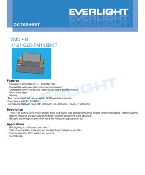
The 17-21/G6C-FM1N2B/3T is a surface-mount device (SMD) LED designed for modern electronic applications requiring compact size, high reliability, and consistent performance. This component represents a significant advancement over traditional lead-frame LEDs, enabling more efficient and miniaturized designs.
1.1 Core Advantages and Product Positioning
The primary advantage of this LED is its extremely small footprint. The 17-21 package is significantly smaller than lead-frame type components, which directly translates to several key benefits for designers and manufacturers. It allows for smaller printed circuit board (PCB) sizes, enabling more compact end products. The high packing density achievable with this SMD format means more components can be placed on a single board, optimizing space utilization. This reduction in component size also leads to decreased storage space requirements during manufacturing and logistics. Ultimately, these factors contribute to the development of smaller, lighter, and more portable electronic equipment. The lightweight nature of the package makes it particularly suitable for applications where weight is a critical factor, such as in portable devices, wearables, and miniature instrumentation.
1.2 Target Market and Applications
This LED is engineered for a broad range of indicator and backlighting applications across multiple industries. Its primary application is in automotive and industrial dashboards, where it serves as an indicator or backlight for switches and gauges, providing clear, reliable illumination. In the telecommunications sector, it is ideal for use as status indicators and keypad backlighting in devices such as telephones and fax machines. Another significant application is providing flat backlighting for liquid crystal displays (LCDs), switches, and symbols, where even and consistent lighting is required. Its general-purpose design also makes it suitable for a wide array of consumer electronics, home appliances, and instrumentation where a brilliant yellow-green indication is needed.
2. In-Depth Technical Parameter Analysis
The performance of the 17-21 LED is defined by a comprehensive set of electrical, optical, and thermal parameters. Understanding these specifications is crucial for proper circuit design and ensuring long-term reliability.
2.1 Absolute Maximum Ratings
These ratings define the stress limits beyond which permanent damage to the device may occur. They should never be exceeded, even momentarily, in normal operation or under fault conditions.
- Reverse Voltage (VR): 5 V. Applying a voltage higher than this in the reverse direction can cause junction breakdown.
- Forward Current (IF): 25 mA. This is the maximum continuous DC current that can flow through the LED.
- Peak Forward Current (IFP): 60 mA. This is the maximum pulsed current, specified at a duty cycle of 1/10 and a frequency of 1 kHz. It is not for continuous operation.
- Power Dissipation (Pd): 60 mW. This is the maximum power the package can dissipate as heat without exceeding its thermal limits.
- Electrostatic Discharge (ESD): 2000 V (Human Body Model). This rating indicates the LED's sensitivity to static electricity; proper ESD handling procedures must be followed.
- Operating Temperature (Topr): -40°C to +85°C. The device is guaranteed to operate within specification across this ambient temperature range.
- Storage Temperature (Tstg): -40°C to +90°C.
- Soldering Temperature (Tsol): The device can withstand reflow soldering with a peak temperature of 260°C for up to 10 seconds, or hand soldering at 350°C for up to 3 seconds per terminal.
2.2 Electro-Optical Characteristics
Measured at a standard test condition of 25°C ambient temperature and a forward current of 20 mA, these parameters define the light output and electrical behavior of the LED.
- Luminous Intensity (Iv): 18.0 - 45.0 mcd (millicandela). The actual output is determined by the bin code (see Section 3). A typical value would be in the middle of this range. The viewing angle (2θ1/2) is typically 140 degrees, providing a wide beam of light.
- Peak Wavelength (λp): Typically 575 nm. This is the wavelength at which the spectral power distribution is at its maximum.
- Dominant Wavelength (λd): 570.0 - 574.5 nm. This parameter more closely correlates with the perceived color of the light, which is a brilliant yellow-green. The specific value is determined by the chromaticity bin.
- Spectral Bandwidth (Δλ): Typically 20 nm. This defines the width of the emitted spectrum at half its maximum power, indicating the color purity.
- Forward Voltage (VF): 1.75 - 2.35 V at IF = 20 mA. The exact value depends on the voltage bin. This is a critical parameter for designing the current-limiting circuit.
- Reverse Current (IR): Maximum 10 μA at VR = 5 V. It is important to note that this device is not designed for operation in reverse bias; this parameter is for leakage test purposes only.
2.3 Thermal Characteristics and Derating
LED performance is highly dependent on temperature. The forward voltage decreases with increasing temperature, while the luminous output also degrades. The derating curve provided in the datasheet shows how the maximum allowable forward current must be reduced as the ambient temperature rises above 25°C to prevent overheating and ensure longevity. For reliable operation, the junction temperature must be kept within safe limits, which is managed by adhering to the power dissipation rating and using appropriate PCB thermal design, such as thermal relief pads or vias.
3. Binning System Explanation
To ensure consistency in mass production, LEDs are sorted into bins based on key performance parameters. This allows designers to select components that meet the specific requirements of their application.
3.1 Luminous Intensity Binning
The luminous output is categorized into four bins: M1, M2, N1, and N2. Each bin covers a specific range of millicandela values measured at 20 mA. For example, bin M1 covers 18.0-22.5 mcd, while bin N2 covers the highest output range of 36.0-45.0 mcd. Designers can specify a bin code to guarantee a minimum brightness level for their application, which is crucial for ensuring uniform appearance in multi-LED arrays or meeting specific visibility thresholds.
3.2 Dominant Wavelength Binning
The color of the emitted light is controlled through dominant wavelength binning. The 17-21 LED uses bins CC2, CC3, and CC4, which correspond to wavelength ranges of 570.0-571.5 nm, 571.5-573.0 nm, and 573.0-574.5 nm, respectively. This tight control (with a tolerance of ±1 nm within a bin) ensures very consistent color from one LED to the next, which is essential for applications where color matching is important, such as in multi-segment displays or status indicators that must appear identical.
3.3 Forward Voltage Binning
The forward voltage is binned into three categories: 0, 1, and 2. Bin 0 covers 1.75-1.95 V, bin 1 covers 1.95-2.15 V, and bin 2 covers 2.15-2.35 V. Knowing the VF bin is important for power supply design. If LEDs with different VF bins are connected in parallel without individual current limiting, they may draw unequal currents due to the slight differences in voltage drop, leading to uneven brightness. Specifying a tight VF bin can help mitigate this issue in parallel configurations or simplify the design of constant-current drivers.
4. Performance Curve Analysis
The datasheet provides several characteristic curves that illustrate the device's behavior under varying conditions. These graphs are invaluable for understanding non-linear relationships and for simulation purposes.
4.1 Relative Luminous Intensity vs. Forward Current
This curve shows that light output is not linearly proportional to current. While output increases with current, the relationship tends to sub-linear at higher currents due to increased thermal effects and efficiency droop. Operating the LED significantly above the recommended 20 mA test current may yield diminishing returns in brightness while drastically reducing lifetime and reliability.
4.2 Relative Luminous Intensity vs. Ambient Temperature
This graph demonstrates the negative impact of temperature on light output. As the ambient (and consequently, junction) temperature rises, the luminous intensity decreases. This thermal quenching effect is a fundamental property of semiconductor light emitters. The curve helps designers estimate the brightness loss in high-temperature environments and may inform decisions about thermal management or drive current compensation.
4.3 Forward Voltage vs. Forward Current (I-V Curve)
The I-V curve exhibits the classic exponential diode characteristic. The "knee" voltage, where current begins to rise sharply, is around the typical VF value. This curve is essential for designing the driving circuit, as it shows that a small change in voltage can cause a large change in current, underscoring the critical need for current regulation rather than voltage regulation.
4.4 Spectrum Distribution and Radiation Pattern
The spectral distribution plot confirms the monochromatic nature of the LED, showing a single peak around 575 nm. The radiation pattern diagram (often a polar plot) illustrates the angular distribution of light intensity. The typical 140-degree viewing angle indicates a Lambertian or near-Lambertian emission pattern, where intensity is highest when viewed head-on and decreases gradually towards the sides.
5. Mechanical and Packaging Information
5.1 Package Dimensions and Polarity Identification
The 17-21 SMD LED has a compact rectangular package. Key dimensions include a body length, width, and height. The cathode is clearly marked, typically by a green dot, a notch, or a beveled corner on the package. Correct polarity identification is crucial during assembly to prevent reverse biasing the device. The recommended PCB land pattern (footprint) is provided to ensure proper soldering and mechanical stability.
5.2 Tape and Reel Packaging
For automated assembly, the LEDs are supplied in 8mm wide embossed carrier tape wound onto 7-inch diameter reels. Each reel contains a standard quantity of 3000 pieces. The reel dimensions and carrier tape pocket specifications are provided to ensure compatibility with standard pick-and-place equipment. The packaging is designed to protect the components from mechanical damage and moisture during storage and transport.
5.3 Moisture Sensitivity and Handling
The components are packaged in a moisture-resistant barrier bag with a desiccant to protect them from ambient humidity, as moisture absorption can cause "popcorning" or delamination during the high-temperature reflow soldering process. The label on the bag provides critical information including the product number, quantity, and the bin codes for luminous intensity (CAT), dominant wavelength (HUE), and forward voltage (REF).
6. Soldering and Assembly Guidelines
Proper soldering is critical to the reliability and performance of SMD components. The datasheet provides detailed instructions to prevent damage.
6.1 Reflow Soldering Profile
A lead-free (Pb-free) reflow temperature profile is specified. Key parameters include: a pre-heating zone from 150-200°C for 60-120 seconds to gradually heat the board and components; a time above liquidus (217°C) of 60-150 seconds; a peak temperature not exceeding 260°C, held for a maximum of 10 seconds; and controlled ramp-up and cool-down rates (max 3°C/sec and 6°C/sec, respectively) to minimize thermal shock. It is strongly recommended that reflow soldering be performed no more than two times on the same LED.
6.2 Hand Soldering Precautions
If hand soldering is necessary, extreme care must be taken. The soldering iron tip temperature should be below 350°C, and contact time with each terminal should not exceed 3 seconds. A low-power iron (25W or less) is recommended. An interval of at least 2 seconds should be left between soldering the two terminals to allow heat dissipation. Mechanical stress should not be applied to the LED during or after soldering.
6.3 Storage and Baking
Unopened moisture-proof bags can be stored under standard factory conditions. Once opened, the LEDs should be used within 168 hours (7 days) if the ambient environment is 30°C/60%RH or less. If not used within this timeframe, or if the desiccant indicator shows saturation, the LEDs must be baked at 60 ±5°C for 24 hours before being subjected to reflow soldering to drive out absorbed moisture.
7. Application Notes and Design Considerations
7.1 Current Limiting is Mandatory
An external current-limiting resistor is absolutely required when driving this LED from a voltage source. Due to the steep I-V characteristic, a small increase in supply voltage can cause a large, potentially destructive, increase in forward current. The resistor value can be calculated using Ohm's Law: R = (Vsupply - VF) / IF. Using the maximum VF from the datasheet for this calculation ensures the current does not exceed the limit even with a low-VF device. For optimal stability, a constant-current driver circuit is recommended, especially for applications requiring precise brightness control or when operating from a variable or poorly regulated voltage source.
7.2 Thermal Management on PCB
Although small, the LED generates heat. For reliable long-term operation, especially at high ambient temperatures or drive currents, attention should be paid to PCB layout for heat dissipation. Using a copper pad under the LED (thermal pad) connected to ground or power planes through thermal vias can help conduct heat away from the junction. Avoiding placing the LED near other heat-generating components is also advisable.
7.3 Optical Design Considerations
The wide 140-degree viewing angle makes this LED suitable for applications requiring broad, even illumination. For applications needing a more focused beam, secondary optics such as lenses or light pipes may be employed. The brilliant yellow-green color is highly visible to the human eye and is often chosen for attention-grabbing indicators. Designers should consider the interaction of the LED's emission with overlays, diffusers, or colored filters to achieve the desired final visual effect.
8. Technical Comparison and Differentiation
The 17-21/G6C-FM1N2B/3T LED offers specific advantages within the landscape of indicator LEDs. Compared to through-hole LEDs, its primary advantage is the massive reduction in board space and assembly cost enabled by surface-mount technology. Compared to other SMD LEDs, its use of AlGaInP (Aluminum Gallium Indium Phosphide) semiconductor material is key. AlGaInP technology is renowned for producing high-efficiency light in the yellow, orange, and red regions of the spectrum. For this brilliant yellow-green color, it typically offers higher luminous efficacy and better temperature stability than older technologies like GaAsP on GaP. The "water clear" resin lens, as opposed to a diffused or colored resin, provides the highest possible light output and a crisp, saturated color point. Its compliance with RoHS, REACH, and halogen-free standards makes it suitable for global markets with strict environmental regulations.
9. Frequently Asked Questions (Based on Technical Parameters)
9.1 Can I drive this LED without a resistor if my supply voltage is exactly 2.0V?
No, this is not recommended and is likely to damage the LED. The forward voltage (VF) is not a fixed value but a range (1.75-2.35V). If you apply 2.0V directly, an LED with a VF of 1.8V (from bin 0) will experience a voltage overdrive of 0.2V. Due to the diode's exponential I-V curve, this small overvoltage can cause the current to exceed the absolute maximum rating, leading to rapid degradation or instant failure. A series resistor is always required for reliable operation from a voltage source.
9.2 Why is the luminous intensity given as a range (18-45 mcd) and not a single value?
Due to inherent variations in the semiconductor manufacturing process, parameters like luminous intensity vary from wafer to wafer and even within a wafer. To provide predictable performance, LEDs are tested and sorted into "bins" based on their measured output. The full range (18-45 mcd) represents the total spread of production. By specifying a bin code (e.g., N1 for 28.5-36.0 mcd), a designer can ensure all LEDs in their product fall within a much tighter, predictable brightness range, guaranteeing consistency in the final application.
9.3 What is the difference between peak wavelength and dominant wavelength?
Peak Wavelength (λp): The specific wavelength at which the spectral power output of the LED is literally at its highest point. It is a physical measurement from the spectrum.
Dominant Wavelength (λd): The wavelength of monochromatic light that, when combined with a specified white reference source, matches the perceived color of the LED. It correlates more directly with what the human eye sees as the "color." For a monochromatic LED like this one, they are often close, but λd is the parameter used for color binning as it better defines visual consistency.
9.4 How do I interpret the ESD rating of 2000V (HBM)?
This rating indicates the LED's robustness against electrostatic discharge according to the Human Body Model (HBM) test standard. A 2000V rating means the device can typically withstand a discharge of up to 2000 volts from a human body (simulated by a 100pF capacitor through a 1.5kΩ resistor). This is a standard level for many commercial components. However, it is still essential to follow ESD-safe handling procedures during assembly, such as using grounded workstations, wrist straps, and conductive containers, to prevent latent damage that may not cause immediate failure but can shorten the device's lifespan.
LED Specification Terminology
Complete explanation of LED technical terms
Photoelectric Performance
| Term | Unit/Representation | Simple Explanation | Why Important |
|---|---|---|---|
| Luminous Efficacy | lm/W (lumens per watt) | Light output per watt of electricity, higher means more energy efficient. | Directly determines energy efficiency grade and electricity cost. |
| Luminous Flux | lm (lumens) | Total light emitted by source, commonly called "brightness". | Determines if the light is bright enough. |
| Viewing Angle | ° (degrees), e.g., 120° | Angle where light intensity drops to half, determines beam width. | Affects illumination range and uniformity. |
| CCT (Color Temperature) | K (Kelvin), e.g., 2700K/6500K | Warmth/coolness of light, lower values yellowish/warm, higher whitish/cool. | Determines lighting atmosphere and suitable scenarios. |
| CRI / Ra | Unitless, 0–100 | Ability to render object colors accurately, Ra≥80 is good. | Affects color authenticity, used in high-demand places like malls, museums. |
| SDCM | MacAdam ellipse steps, e.g., "5-step" | Color consistency metric, smaller steps mean more consistent color. | Ensures uniform color across same batch of LEDs. |
| Dominant Wavelength | nm (nanometers), e.g., 620nm (red) | Wavelength corresponding to color of colored LEDs. | Determines hue of red, yellow, green monochrome LEDs. |
| Spectral Distribution | Wavelength vs intensity curve | Shows intensity distribution across wavelengths. | Affects color rendering and quality. |
Electrical Parameters
| Term | Symbol | Simple Explanation | Design Considerations |
|---|---|---|---|
| Forward Voltage | Vf | Minimum voltage to turn on LED, like "starting threshold". | Driver voltage must be ≥Vf, voltages add up for series LEDs. |
| Forward Current | If | Current value for normal LED operation. | Usually constant current drive, current determines brightness & lifespan. |
| Max Pulse Current | Ifp | Peak current tolerable for short periods, used for dimming or flashing. | Pulse width & duty cycle must be strictly controlled to avoid damage. |
| Reverse Voltage | Vr | Max reverse voltage LED can withstand, beyond may cause breakdown. | Circuit must prevent reverse connection or voltage spikes. |
| Thermal Resistance | Rth (°C/W) | Resistance to heat transfer from chip to solder, lower is better. | High thermal resistance requires stronger heat dissipation. |
| ESD Immunity | V (HBM), e.g., 1000V | Ability to withstand electrostatic discharge, higher means less vulnerable. | Anti-static measures needed in production, especially for sensitive LEDs. |
Thermal Management & Reliability
| Term | Key Metric | Simple Explanation | Impact |
|---|---|---|---|
| Junction Temperature | Tj (°C) | Actual operating temperature inside LED chip. | Every 10°C reduction may double lifespan; too high causes light decay, color shift. |
| Lumen Depreciation | L70 / L80 (hours) | Time for brightness to drop to 70% or 80% of initial. | Directly defines LED "service life". |
| Lumen Maintenance | % (e.g., 70%) | Percentage of brightness retained after time. | Indicates brightness retention over long-term use. |
| Color Shift | Δu′v′ or MacAdam ellipse | Degree of color change during use. | Affects color consistency in lighting scenes. |
| Thermal Aging | Material degradation | Deterioration due to long-term high temperature. | May cause brightness drop, color change, or open-circuit failure. |
Packaging & Materials
| Term | Common Types | Simple Explanation | Features & Applications |
|---|---|---|---|
| Package Type | EMC, PPA, Ceramic | Housing material protecting chip, providing optical/thermal interface. | EMC: good heat resistance, low cost; Ceramic: better heat dissipation, longer life. |
| Chip Structure | Front, Flip Chip | Chip electrode arrangement. | Flip chip: better heat dissipation, higher efficacy, for high-power. |
| Phosphor Coating | YAG, Silicate, Nitride | Covers blue chip, converts some to yellow/red, mixes to white. | Different phosphors affect efficacy, CCT, and CRI. |
| Lens/Optics | Flat, Microlens, TIR | Optical structure on surface controlling light distribution. | Determines viewing angle and light distribution curve. |
Quality Control & Binning
| Term | Binning Content | Simple Explanation | Purpose |
|---|---|---|---|
| Luminous Flux Bin | Code e.g., 2G, 2H | Grouped by brightness, each group has min/max lumen values. | Ensures uniform brightness in same batch. |
| Voltage Bin | Code e.g., 6W, 6X | Grouped by forward voltage range. | Facilitates driver matching, improves system efficiency. |
| Color Bin | 5-step MacAdam ellipse | Grouped by color coordinates, ensuring tight range. | Guarantees color consistency, avoids uneven color within fixture. |
| CCT Bin | 2700K, 3000K etc. | Grouped by CCT, each has corresponding coordinate range. | Meets different scene CCT requirements. |
Testing & Certification
| Term | Standard/Test | Simple Explanation | Significance |
|---|---|---|---|
| LM-80 | Lumen maintenance test | Long-term lighting at constant temperature, recording brightness decay. | Used to estimate LED life (with TM-21). |
| TM-21 | Life estimation standard | Estimates life under actual conditions based on LM-80 data. | Provides scientific life prediction. |
| IESNA | Illuminating Engineering Society | Covers optical, electrical, thermal test methods. | Industry-recognized test basis. |
| RoHS / REACH | Environmental certification | Ensures no harmful substances (lead, mercury). | Market access requirement internationally. |
| ENERGY STAR / DLC | Energy efficiency certification | Energy efficiency and performance certification for lighting. | Used in government procurement, subsidy programs, enhances competitiveness. |