1. Product Overview
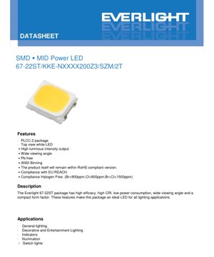
The 67-22ST is a surface-mount mid-power LED housed in a PLCC-2 package. It is designed to deliver high luminous efficacy and excellent color rendering across a wide viewing angle, making it suitable for a broad range of general and decorative lighting applications. The device features a top-view white light emission and is constructed with environmentally friendly materials, being Pb-free, compliant with RoHS and EU REACH regulations, and meeting halogen-free standards (Br<900ppm, Cl<900ppm, Br+Cl<1500ppm). Its compact form factor and reliable performance position it as an ideal solution for modern lighting designs.
1.1 Core Advantages
- High luminous intensity and efficacy output.
- Wide viewing angle (typically 120 degrees).
- Available with high Color Rendering Index (CRI) options (Min. 60 to 90).
- Low power consumption.
- Pb-free and compliant with major environmental directives (RoHS, REACH, Halogen-Free).
- Standard ANSI binning for consistent color quality.
1.2 Target Applications
- General lighting fixtures.
- Decorative and entertainment lighting.
- Indicator lights.
- General illumination.
- Switch backlighting.
2. In-Depth Technical Parameter Analysis
2.1 Absolute Maximum Ratings
The following ratings define the limits beyond which permanent damage to the device may occur. All parameters are specified at a soldering point temperature (TSoldering) of 25°C.
| Parameter | Symbol | Rating | Unit |
|---|---|---|---|
| Forward Current | IF | 30 | mA |
| Peak Forward Current (Duty 1/10 @10ms) | IFP | 60 | mA |
| Power Dissipation | Pd | 600 | mW |
| Operating Temperature | Topr | -40 to +85 | °C |
| Storage Temperature | Tstg | -40 to +100 | °C |
| Thermal Resistance (Junction to Soldering point) | Rth J-S | 21 | °C/W |
| Junction Temperature | Tj | 115 | °C |
| Soldering Temperature | Tsol | Reflow: 260°C for 10s Hand: 350°C for 3s | °C |
Note: This product is sensitive to electrostatic discharge (ESD). Proper ESD handling precautions must be observed during assembly and handling.
2.2 Electro-Optical Characteristics
The typical performance is measured at TSoldering = 25°C and IF = 30mA.
| Parameter | Symbol | Min. | Typ. | Max. | Unit | Condition |
|---|---|---|---|---|---|---|
| Luminous Flux | Φ | 65 | 75 | 85 | lm | IF=30mA |
| Forward Voltage | VF | 17 | 18.5 | 20 | V | IF=30mA |
| Color Rendering Index | Ra | 80 | 82 | 86 | - | IF=30mA |
| R9 Value | R9 | 0 | 4 | 15 | - | IF=30mA |
| Viewing Angle (2θ1/2) | 2θ1/2 | 115 | 120 | 125 | deg | IF=30mA |
Notes: Luminous flux tolerance is ±11%. Forward voltage tolerance is ±0.1V. CRI tolerance is ±2.
2.3 Thermal Characteristics
The thermal resistance from the junction to the soldering point (Rth J-S) is 21°C/W. This parameter is critical for thermal management design. Exceeding the maximum junction temperature (Tj = 115°C) will significantly reduce the LED's lifetime and luminous output. Proper PCB layout with adequate thermal vias and, if necessary, a heatsink is recommended for high-power or high-ambient-temperature applications.
3. Binning System Explanation
The product uses a comprehensive binning system to ensure color consistency and electrical performance matching.
3.1 Color Rendering Index (CRI) Binning
The CRI is indicated by a single letter in the product number. The available bins are:
| Symbol | CRI (Min.) |
|---|---|
| M | 60 |
| N | 65 |
| L | 70 |
| Q | 75 |
| K | 80 |
| P | 85 |
| H | 90 |
Tolerance for CRI is ±2.
3.2 Luminous Flux Binning
Luminous flux is binned in 5 lm steps, as shown below for the typical product variant.
| Bin Code | Min. Luminous Flux (lm) | Max. Luminous Flux (lm) | Condition |
|---|---|---|---|
| 6570 | 65 | 70 | IF = 30 mA |
| 7075 | 70 | 75 | |
| 7580 | 75 | 80 | |
| 8085 | 80 | 85 |
Tolerance for luminous flux is ±11%.
3.3 Forward Voltage Binning
Forward voltage is grouped and binned in 0.5V steps under Group 'A'.
| Group | Bin Code | Min. VF (V) | Max. VF (V) | Condition |
|---|---|---|---|---|
| A | A70 | 17.0 | 17.5 | IF = 30 mA |
| A75 | 17.5 | 18.0 | ||
| A80 | 18.0 | 18.5 | ||
| A85 | 18.5 | 19.0 | ||
| A90 | 19.0 | 19.5 | ||
| A95 | 19.5 | 20.0 |
Tolerance for forward voltage is ±0.1V.
3.4 Chromaticity and Correlated Color Temperature (CCT) Binning
The LED is available in several CCTs: 2700K (Warm White), 3000K, 4000K (Neutral White), 5000K, and 6500K (Cool White). For each CCT, precise chromaticity coordinates (CIE x, y) are defined within specific bin ranges on the CIE 1931 chromaticity diagram. The datasheet provides detailed coordinate sets for 3-STEP, 5-STEP, and 7-STEP MacAdam ellipse binning, ensuring tight color consistency. For example, the 2700K CCT has defined bins like 27-M3, 27-M5, and 27-7A through 27-7D, each with a specific quadrilateral area on the chromaticity diagram and a reference CCT range (e.g., 2580K~2718K for bin 27-7A).
4. Product Number Explanation and Ordering Guide
The product number follows a specific structure: 67-22ST/ KKE – N XX XX XXX Z3 /SZM/ 2 T
- 67-22ST/: Base product code for the PLCC-2 mid-power LED.
- KKE: Specific series or internal code.
- – N: Color Rendering Index code (e.g., 'K' for CRI 80 Min.).
- XX XX: Codes for CCT and minimum luminous flux (e.g., '2765' for 2700K and 65 lm min).
- XXX: Forward voltage index (e.g., '200' for VF max of 20.0V).
- Z3: Forward current index (IF = 30mA).
- /SZM/2T: Packaging and tape specification.
Example: 67-22ST/KKE-N2765200Z3/SZM/2T decodes as: CRI 80 (Min.), CCT 2700K, Flux 65 lm min, VF 20.0V max, IF 30mA.
5. Mass Production List
The following standard products are available for mass production. All have a CRI of 80 (Min.) and a forward current of 30mA.
| Product Number | CRI (Min.) | CCT | Luminous Flux Φ (lm) Min. |
|---|---|---|---|
| 67-22ST/KKE-N2765200Z3/SZM/2T | 80 | 2700K | 65 |
| 67-22ST/KKE-N3065200Z3/SZM/2T | 80 | 3000K | 65 |
| 67-22ST/KKE-N4070200Z3/SZM/2T | 80 | 4000K | 70 |
| 67-22ST/KKE-N5070200Z3/SZM/2T | 80 | 5000K | 70 |
| 67-22ST/KKE-N6570200Z3/SZM/2T | 80 | 6500K | 70 |
6. Application Suggestions and Design Considerations
6.1 Typical Application Scenarios
- General Lighting: Ideal for LED bulbs, tubes, and panel lights due to high efficacy and good CRI.
- Decorative Lighting: Suitable for accent lighting, cove lighting, and signage where consistent white light is required.
- Indicator & Backlighting: Can be used in appliances and switches, leveraging its wide viewing angle.
6.2 Design Considerations
- Current Driving: Operate at or below the recommended 30mA continuous current. Use a constant current driver for stable performance and longevity.
- Thermal Management: The 21°C/W thermal resistance necessitates effective heat sinking on the PCB. Ensure the maximum junction temperature is not exceeded.
- Optics: The 120-degree viewing angle provides broad, even illumination. For focused beams, secondary optics (lenses) may be required.
- Binning Selection: For applications requiring color consistency (e.g., multi-LED fixtures), specify tight CCT and flux bins (e.g., 3-STEP or 5-STEP).
7. Soldering and Assembly Guidelines
- Reflow Soldering: Maximum peak temperature of 260°C for 10 seconds. Follow a standard lead-free reflow profile.
- Hand Soldering: Iron tip temperature should not exceed 350°C, and contact time should be limited to 3 seconds per pad.
- Cleaning: Use no-clean flux if possible. If cleaning is necessary, ensure the cleaning agent is compatible with the LED's resin.
- Storage: Store in a dry, anti-static environment at temperatures between -40°C and +100°C. Use within 12 months of the manufacturing date for optimal solderability.
8. Packaging Information
The product is supplied on embossed carrier tape and reel, suitable for automated pick-and-place assembly machines. The specific packaging code '/SZM/2T' indicates the tape width, pocket spacing, and reel size. Standard reel quantities vary based on the specific product bin.
9. Frequently Asked Questions (FAQ)
Q: What is the typical forward voltage for this LED?
A: The typical forward voltage (VF) at 30mA is 18.5V, with a maximum of 20.0V. It is binned in 0.5V steps from 17.0V to 20.0V.
Q: How is the Color Rendering Index (CRI) specified?
A: CRI is specified as a minimum value (e.g., 80 Min.) with a tolerance of ±2. The R9 value (saturated red) is also provided, typically ranging from 0 to 15 for the CRI 80 version.
Q: What are the key thermal limits?
A> The maximum junction temperature (Tj) is 115°C. The thermal resistance from junction to soldering point is 21°C/W. Proper heat sinking is essential to maintain Tj below this limit during operation.
Q: Can multiple LEDs be connected in series?
A> Yes, but the driver voltage must accommodate the sum of the individual forward voltages. For example, three LEDs with a typical VF of 18.5V would require a driver capable of supplying at least 55.5V at 30mA.
10. Technical Comparison and Positioning
The 67-22ST LED occupies the mid-power segment. Compared to traditional low-power LEDs, it offers significantly higher luminous flux per device, reducing the number of LEDs needed for a given light output. Compared to high-power LEDs, it typically has a lower thermal density, which can simplify thermal management in some designs. Its wide 120-degree viewing angle is a key differentiator from LEDs with narrower beams, making it preferable for applications requiring even, diffuse illumination without secondary optics.
11. Operating Principle Introduction
This LED is based on InGaN (Indium Gallium Nitride) semiconductor technology. When a forward voltage is applied, electrons and holes recombine within the active region of the chip, releasing energy in the form of photons (light). The specific composition of the InGaN layers determines the emission of blue light. This blue light then excites a phosphor coating (YAG:Ce or similar) inside the package, which down-converts a portion of the blue light to longer wavelengths (yellow, red), resulting in the perception of white light. The balance between blue and phosphor-converted light determines the Correlated Color Temperature (CCT).
12. Industry Trends
The lighting industry continues to demand higher efficacy (lumens per watt), improved color quality (higher CRI and better R9 values), and greater reliability. Mid-power LEDs like the 67-22ST are central to this trend, offering an optimal balance of performance, cost, and design flexibility. Future developments may focus on further efficacy gains through chip and phosphor improvements, enhanced color consistency through tighter binning, and integration of driver electronics for smarter lighting solutions. The emphasis on sustainability drives compliance with stricter environmental standards, which this product already addresses.
LED Specification Terminology
Complete explanation of LED technical terms
Photoelectric Performance
| Term | Unit/Representation | Simple Explanation | Why Important |
|---|---|---|---|
| Luminous Efficacy | lm/W (lumens per watt) | Light output per watt of electricity, higher means more energy efficient. | Directly determines energy efficiency grade and electricity cost. |
| Luminous Flux | lm (lumens) | Total light emitted by source, commonly called "brightness". | Determines if the light is bright enough. |
| Viewing Angle | ° (degrees), e.g., 120° | Angle where light intensity drops to half, determines beam width. | Affects illumination range and uniformity. |
| CCT (Color Temperature) | K (Kelvin), e.g., 2700K/6500K | Warmth/coolness of light, lower values yellowish/warm, higher whitish/cool. | Determines lighting atmosphere and suitable scenarios. |
| CRI / Ra | Unitless, 0–100 | Ability to render object colors accurately, Ra≥80 is good. | Affects color authenticity, used in high-demand places like malls, museums. |
| SDCM | MacAdam ellipse steps, e.g., "5-step" | Color consistency metric, smaller steps mean more consistent color. | Ensures uniform color across same batch of LEDs. |
| Dominant Wavelength | nm (nanometers), e.g., 620nm (red) | Wavelength corresponding to color of colored LEDs. | Determines hue of red, yellow, green monochrome LEDs. |
| Spectral Distribution | Wavelength vs intensity curve | Shows intensity distribution across wavelengths. | Affects color rendering and quality. |
Electrical Parameters
| Term | Symbol | Simple Explanation | Design Considerations |
|---|---|---|---|
| Forward Voltage | Vf | Minimum voltage to turn on LED, like "starting threshold". | Driver voltage must be ≥Vf, voltages add up for series LEDs. |
| Forward Current | If | Current value for normal LED operation. | Usually constant current drive, current determines brightness & lifespan. |
| Max Pulse Current | Ifp | Peak current tolerable for short periods, used for dimming or flashing. | Pulse width & duty cycle must be strictly controlled to avoid damage. |
| Reverse Voltage | Vr | Max reverse voltage LED can withstand, beyond may cause breakdown. | Circuit must prevent reverse connection or voltage spikes. |
| Thermal Resistance | Rth (°C/W) | Resistance to heat transfer from chip to solder, lower is better. | High thermal resistance requires stronger heat dissipation. |
| ESD Immunity | V (HBM), e.g., 1000V | Ability to withstand electrostatic discharge, higher means less vulnerable. | Anti-static measures needed in production, especially for sensitive LEDs. |
Thermal Management & Reliability
| Term | Key Metric | Simple Explanation | Impact |
|---|---|---|---|
| Junction Temperature | Tj (°C) | Actual operating temperature inside LED chip. | Every 10°C reduction may double lifespan; too high causes light decay, color shift. |
| Lumen Depreciation | L70 / L80 (hours) | Time for brightness to drop to 70% or 80% of initial. | Directly defines LED "service life". |
| Lumen Maintenance | % (e.g., 70%) | Percentage of brightness retained after time. | Indicates brightness retention over long-term use. |
| Color Shift | Δu′v′ or MacAdam ellipse | Degree of color change during use. | Affects color consistency in lighting scenes. |
| Thermal Aging | Material degradation | Deterioration due to long-term high temperature. | May cause brightness drop, color change, or open-circuit failure. |
Packaging & Materials
| Term | Common Types | Simple Explanation | Features & Applications |
|---|---|---|---|
| Package Type | EMC, PPA, Ceramic | Housing material protecting chip, providing optical/thermal interface. | EMC: good heat resistance, low cost; Ceramic: better heat dissipation, longer life. |
| Chip Structure | Front, Flip Chip | Chip electrode arrangement. | Flip chip: better heat dissipation, higher efficacy, for high-power. |
| Phosphor Coating | YAG, Silicate, Nitride | Covers blue chip, converts some to yellow/red, mixes to white. | Different phosphors affect efficacy, CCT, and CRI. |
| Lens/Optics | Flat, Microlens, TIR | Optical structure on surface controlling light distribution. | Determines viewing angle and light distribution curve. |
Quality Control & Binning
| Term | Binning Content | Simple Explanation | Purpose |
|---|---|---|---|
| Luminous Flux Bin | Code e.g., 2G, 2H | Grouped by brightness, each group has min/max lumen values. | Ensures uniform brightness in same batch. |
| Voltage Bin | Code e.g., 6W, 6X | Grouped by forward voltage range. | Facilitates driver matching, improves system efficiency. |
| Color Bin | 5-step MacAdam ellipse | Grouped by color coordinates, ensuring tight range. | Guarantees color consistency, avoids uneven color within fixture. |
| CCT Bin | 2700K, 3000K etc. | Grouped by CCT, each has corresponding coordinate range. | Meets different scene CCT requirements. |
Testing & Certification
| Term | Standard/Test | Simple Explanation | Significance |
|---|---|---|---|
| LM-80 | Lumen maintenance test | Long-term lighting at constant temperature, recording brightness decay. | Used to estimate LED life (with TM-21). |
| TM-21 | Life estimation standard | Estimates life under actual conditions based on LM-80 data. | Provides scientific life prediction. |
| IESNA | Illuminating Engineering Society | Covers optical, electrical, thermal test methods. | Industry-recognized test basis. |
| RoHS / REACH | Environmental certification | Ensures no harmful substances (lead, mercury). | Market access requirement internationally. |
| ENERGY STAR / DLC | Energy efficiency certification | Energy efficiency and performance certification for lighting. | Used in government procurement, subsidy programs, enhances competitiveness. |