Table of Contents
- 1. Product Overview
- 2. Technical Parameter Deep Dive
- 2.1 Absolute Maximum Ratings
- 2.2 Electro-Optical Characteristics
- 3. Binning System Explanation
- 3.1 Product Number Decoding
- 3.2 Luminous Flux Binning
- 3.3 Forward Voltage Binning
- 3.4 Chromaticity Coordinate Binning
- 4. Application Suggestions
- 4.1 Typical Application Scenarios
- 4.2 Design Considerations
- 5. Soldering and Assembly Guide
- 5.1 Reflow Soldering Parameters
- 5.2 Hand Soldering
- 5.3 Storage Conditions
- 6. Packaging and Ordering Information
- 7. Technical Comparison and Positioning
- 8. Frequently Asked Questions (Based on Technical Parameters)
- 8.1 What is the actual power consumption of this LED?
- 8.2 How do I select the right CCT and CRI for my application?
- 8.3 Why is thermal management so important?
- 9. Practical Design Case
- 10. Operating Principle and Technology Trends
- 10.1 Basic Operating Principle
- 10.2 Industry Trends
- LED Specification Terminology
- Photoelectric Performance
- Electrical Parameters
- Thermal Management & Reliability
- Packaging & Materials
- Quality Control & Binning
- Testing & Certification
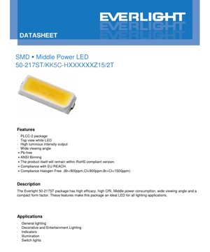
1. Product Overview
This document details the specifications for a surface-mount device (SMD) LED utilizing a PLCC-2 (Plastic Leaded Chip Carrier) package. This component is classified as a middle-power LED, designed to offer a balance between luminous output and power consumption. The primary emitted color is white, available in various correlated color temperatures (CCTs) including warm white, neutral white, and cool white. The package features a top-view design and is constructed with water-clear resin for optimal light extraction.
The core advantages of this LED series include high luminous efficacy, a wide viewing angle of 120 degrees, and compliance with modern environmental and safety standards such as RoHS, REACH, and halogen-free requirements. Its compact form factor and reliable performance make it suitable for a broad range of general and decorative lighting applications.
2. Technical Parameter Deep Dive
2.1 Absolute Maximum Ratings
The device's operational limits are defined under specific conditions (soldering point temperature at 25°C). Exceeding these ratings may cause permanent damage.
- Forward Current (IF): 150 mA (continuous).
- Peak Forward Current (IFP): 300 mA, permissible under pulsed conditions with a duty cycle of 1/10 and pulse width of 10ms.
- Power Dissipation (Pd): 510 mW maximum.
- Operating Temperature (Topr): -40°C to +85°C.
- Storage Temperature (Tstg): -40°C to +100°C.
- Thermal Resistance (Rth J-S): 32 °C/W (junction to soldering point).
- Junction Temperature (Tj): 115 °C maximum.
- Soldering Temperature: Reflow soldering is specified at 260°C for 10 seconds. Hand soldering is allowed at 350°C for a maximum of 3 seconds.
Important Note: This product is sensitive to electrostatic discharge (ESD). Proper ESD handling procedures must be followed during assembly and handling.
2.2 Electro-Optical Characteristics
Key performance parameters are measured at a forward current (IF) of 150 mA and a soldering point temperature of 25°C.
- Luminous Flux (Φ): The minimum value varies by product variant, starting from 55 lumens. A typical tolerance of ±11% applies.
- Forward Voltage (VF): Ranges from a typical minimum of 2.8V to a maximum of 3.4V at 150mA. Tolerance is ±0.1V.
- Color Rendering Index (CRI/Ra): A minimum of 80 is guaranteed for the listed variants, with a tolerance of ±2.
- Viewing Angle (2θ1/2): 120 degrees (typical).
- Reverse Current (IR): Maximum 50 µA at a reverse voltage (VR) of 5V.
3. Binning System Explanation
The product uses a comprehensive binning system to ensure color and performance consistency. The product number itself encodes key bin information.
3.1 Product Number Decoding
The part number structure, for example 50-217ST/KK5C-H275534Z15/2T, contains several key identifiers:
- CRI Code: 'K' indicates a minimum CRI of 80.
- CCT Code: '27' indicates a Correlated Color Temperature of 2700K (warm white). Other codes include 30 (3000K), 40 (4000K), 50 (5000K), 57 (5700K), and 65 (6500K).
- Luminous Flux Bin: '55' indicates a minimum luminous flux of 55 lumens for this specific CCT/CRI combination.
- Forward Voltage Bin: '34' indicates a maximum forward voltage of 3.4V.
- Forward Current Index: 'Z15' specifies the operating forward current of 150mA.
3.2 Luminous Flux Binning
Luminous output is categorized into bins denoted by codes like R2, R3, etc., each defining a min/max flux range at 150mA. For instance, bin R2 covers 55 to 60 lm. The standard tolerance for luminous flux is ±11%.
3.3 Forward Voltage Binning
Forward voltage is binned using two-digit codes from 35 to 40. Each bin represents a 0.1V range, starting from 2.8-2.9V (bin 35) up to 3.3-3.4V (bin 40). The tolerance is ±0.1V.
3.4 Chromaticity Coordinate Binning
For precise color control, chromaticity coordinates (x, y on the CIE 1931 diagram) are tightly binned within each CCT group. The datasheet provides detailed tables with coordinate boundaries for multiple sub-bins (e.g., 27K-A, 27K-B for 2700K). This ensures LEDs from the same bin will appear visually identical in color. Reference ranges define the target CCT for each main bin group.
4. Application Suggestions
4.1 Typical Application Scenarios
- General Lighting: Ideal for LED bulbs, tubes, and panels where a balance of efficiency, light quality, and cost is required.
- Decorative and Entertainment Lighting: Suitable for accent lighting, signage, and stage lighting due to its wide viewing angle and available CCTs.
- Indicator Lights: Can be used for status indicators requiring higher brightness than standard LEDs.
- Switch Lights: Applicable for illuminated switches and control panels.
4.2 Design Considerations
- Thermal Management: With a thermal resistance of 32°C/W, proper PCB layout and heat sinking are crucial to maintain junction temperature below 115°C, especially when operating at the maximum forward current. This ensures long-term reliability and stable light output.
- Current Drive: A constant current driver is recommended to ensure stable luminous output and color consistency. The driver should be designed to not exceed the absolute maximum ratings for forward and peak current.
- Optical Design: The 120-degree viewing angle is a typical value. For specific beam patterns, secondary optics (lenses, reflectors) may be required.
5. Soldering and Assembly Guide
5.1 Reflow Soldering Parameters
The component is compatible with standard infrared or convection reflow processes. The critical parameter is a peak temperature of 260°C, which should not be exceeded for more than 10 seconds. The recommended reflow profile should follow JEDEC or IPC standards for SMD components.
5.2 Hand Soldering
If hand soldering is necessary, extreme care must be taken. The iron tip temperature should be limited to 350°C, and contact time with any single lead must not exceed 3 seconds to prevent thermal damage to the plastic package and the LED chip.
5.3 Storage Conditions
To preserve solderability and prevent moisture absorption (which can cause "popcorning" during reflow), components should be stored in their original moisture-barrier bags with desiccant in a controlled environment. The storage temperature range is -40°C to +100°C.
6. Packaging and Ordering Information
The standard packaging quantity is indicated in the part number suffix (/2T likely refers to tape and reel packaging). For specific reel quantities and packaging dimensions, consult the manufacturer's packaging specification document. Always order using the full product number to guarantee receipt of the correct CCT, CRI, flux, and voltage bin.
7. Technical Comparison and Positioning
As a middle-power LED in a PLCC-2 package, this product sits between low-power indicator LEDs and high-power illumination LEDs. Its key differentiators are:
- vs. Low-Power LEDs: Offers significantly higher luminous flux, making it suitable for illumination rather than just indication.
- vs. High-Power LEDs: Typically operates at lower current and has a simpler package, often leading to lower system cost and simpler drive circuitry, while still providing good efficacy for many applications.
- Package Advantage: The PLCC-2 package provides a stable mechanical structure and good thermal path compared to simpler SMD packages like 0603 or 0805.
8. Frequently Asked Questions (Based on Technical Parameters)
8.1 What is the actual power consumption of this LED?
Power consumption is calculated as Forward Voltage (VF) × Forward Current (IF). At the typical maximum condition (3.4V, 150mA), the power is 0.51W, which matches the maximum power dissipation rating. Actual power will vary slightly depending on the specific VF bin of the LED.
8.2 How do I select the right CCT and CRI for my application?
Choose CCT based on the desired "warmth" of the white light: 2700K-3000K for warm, cozy light (similar to incandescent); 4000K-5000K for neutral white (common in offices); 5700K-6500K for cool, daylight-like white. A CRI of 80 (min) is suitable for general lighting where excellent color fidelity is not critical. For retail or museum lighting, a higher CRI variant (if available) would be preferable.
8.3 Why is thermal management so important?
LED efficacy and lifetime degrade as junction temperature increases. Exceeding the maximum junction temperature (115°C) can cause rapid failure. The thermal resistance of 32°C/W means that for every watt dissipated, the junction will be 32°C hotter than the soldering point. Therefore, keeping the PCB temperature low via good design is essential for performance and longevity.
9. Practical Design Case
Scenario: Designing a 2700K warm white LED bulb as a replacement for a 40W incandescent bulb, targeting approximately 450 lumens.
Implementation:
- LED Selection: Choose the
50-217ST/KK5C-H275534Z15/2Tvariant (2700K, 80 CRI min, 55 lm min). - Quantity Calculation: To achieve 450 lumens, a minimum of 9 LEDs (450 lm / 55 lm per LED) would be required, arranged in series, parallel, or a series-parallel combination.
- Driver Design: A constant current driver outputting 150mA is needed. If all 9 LEDs are in series, the driver's output voltage must accommodate the sum of the individual VF values (9 * ~3.2V ≈ 28.8V).
- Thermal Design: The total power dissipation would be approximately 9 * 0.48W = 4.32W. The PCB must be designed with adequate copper area or be attached to a metal heatsink to keep the LED soldering points sufficiently cool, ensuring the junction temperature remains within safe limits.
- Optical Design: A diffuser cover would be used to blend the light from the multiple discrete sources into a uniform beam.
10. Operating Principle and Technology Trends
10.1 Basic Operating Principle
This white LED is based on a semiconductor chip, typically made of InGaN (Indium Gallium Nitride), which emits light in the blue or ultraviolet spectrum when electrical current passes through it in the forward direction. This primary light then excites a phosphor coating (YAG:Ce or similar) inside the package. The phosphor down-converts a portion of the primary light to longer wavelengths (yellow, red). The mixture of the remaining blue light and the phosphor-emitted light results in the perception of white light. The specific blend of phosphors determines the CCT and CRI of the output.
10.2 Industry Trends
The development of mid-power LEDs like this one is driven by several key trends:
- Increased Efficacy (lm/W): Ongoing improvements in chip design, phosphor technology, and package efficiency lead to higher light output for the same electrical input, reducing energy consumption.
- Improved Color Quality: There is a continuous push for higher CRI values and more consistent color rendering across batches, facilitated by advanced binning systems and phosphor formulations.
- Miniaturization and Integration:
- Standardization and Cost Reduction: As volumes increase, packaging and manufacturing processes become more standardized, leading to lower costs and wider adoption across diverse lighting applications.
This component represents a mature and optimized solution within this evolving landscape, offering a reliable combination of performance, quality, and cost-effectiveness for mainstream lighting needs.
LED Specification Terminology
Complete explanation of LED technical terms
Photoelectric Performance
| Term | Unit/Representation | Simple Explanation | Why Important |
|---|---|---|---|
| Luminous Efficacy | lm/W (lumens per watt) | Light output per watt of electricity, higher means more energy efficient. | Directly determines energy efficiency grade and electricity cost. |
| Luminous Flux | lm (lumens) | Total light emitted by source, commonly called "brightness". | Determines if the light is bright enough. |
| Viewing Angle | ° (degrees), e.g., 120° | Angle where light intensity drops to half, determines beam width. | Affects illumination range and uniformity. |
| CCT (Color Temperature) | K (Kelvin), e.g., 2700K/6500K | Warmth/coolness of light, lower values yellowish/warm, higher whitish/cool. | Determines lighting atmosphere and suitable scenarios. |
| CRI / Ra | Unitless, 0–100 | Ability to render object colors accurately, Ra≥80 is good. | Affects color authenticity, used in high-demand places like malls, museums. |
| SDCM | MacAdam ellipse steps, e.g., "5-step" | Color consistency metric, smaller steps mean more consistent color. | Ensures uniform color across same batch of LEDs. |
| Dominant Wavelength | nm (nanometers), e.g., 620nm (red) | Wavelength corresponding to color of colored LEDs. | Determines hue of red, yellow, green monochrome LEDs. |
| Spectral Distribution | Wavelength vs intensity curve | Shows intensity distribution across wavelengths. | Affects color rendering and quality. |
Electrical Parameters
| Term | Symbol | Simple Explanation | Design Considerations |
|---|---|---|---|
| Forward Voltage | Vf | Minimum voltage to turn on LED, like "starting threshold". | Driver voltage must be ≥Vf, voltages add up for series LEDs. |
| Forward Current | If | Current value for normal LED operation. | Usually constant current drive, current determines brightness & lifespan. |
| Max Pulse Current | Ifp | Peak current tolerable for short periods, used for dimming or flashing. | Pulse width & duty cycle must be strictly controlled to avoid damage. |
| Reverse Voltage | Vr | Max reverse voltage LED can withstand, beyond may cause breakdown. | Circuit must prevent reverse connection or voltage spikes. |
| Thermal Resistance | Rth (°C/W) | Resistance to heat transfer from chip to solder, lower is better. | High thermal resistance requires stronger heat dissipation. |
| ESD Immunity | V (HBM), e.g., 1000V | Ability to withstand electrostatic discharge, higher means less vulnerable. | Anti-static measures needed in production, especially for sensitive LEDs. |
Thermal Management & Reliability
| Term | Key Metric | Simple Explanation | Impact |
|---|---|---|---|
| Junction Temperature | Tj (°C) | Actual operating temperature inside LED chip. | Every 10°C reduction may double lifespan; too high causes light decay, color shift. |
| Lumen Depreciation | L70 / L80 (hours) | Time for brightness to drop to 70% or 80% of initial. | Directly defines LED "service life". |
| Lumen Maintenance | % (e.g., 70%) | Percentage of brightness retained after time. | Indicates brightness retention over long-term use. |
| Color Shift | Δu′v′ or MacAdam ellipse | Degree of color change during use. | Affects color consistency in lighting scenes. |
| Thermal Aging | Material degradation | Deterioration due to long-term high temperature. | May cause brightness drop, color change, or open-circuit failure. |
Packaging & Materials
| Term | Common Types | Simple Explanation | Features & Applications |
|---|---|---|---|
| Package Type | EMC, PPA, Ceramic | Housing material protecting chip, providing optical/thermal interface. | EMC: good heat resistance, low cost; Ceramic: better heat dissipation, longer life. |
| Chip Structure | Front, Flip Chip | Chip electrode arrangement. | Flip chip: better heat dissipation, higher efficacy, for high-power. |
| Phosphor Coating | YAG, Silicate, Nitride | Covers blue chip, converts some to yellow/red, mixes to white. | Different phosphors affect efficacy, CCT, and CRI. |
| Lens/Optics | Flat, Microlens, TIR | Optical structure on surface controlling light distribution. | Determines viewing angle and light distribution curve. |
Quality Control & Binning
| Term | Binning Content | Simple Explanation | Purpose |
|---|---|---|---|
| Luminous Flux Bin | Code e.g., 2G, 2H | Grouped by brightness, each group has min/max lumen values. | Ensures uniform brightness in same batch. |
| Voltage Bin | Code e.g., 6W, 6X | Grouped by forward voltage range. | Facilitates driver matching, improves system efficiency. |
| Color Bin | 5-step MacAdam ellipse | Grouped by color coordinates, ensuring tight range. | Guarantees color consistency, avoids uneven color within fixture. |
| CCT Bin | 2700K, 3000K etc. | Grouped by CCT, each has corresponding coordinate range. | Meets different scene CCT requirements. |
Testing & Certification
| Term | Standard/Test | Simple Explanation | Significance |
|---|---|---|---|
| LM-80 | Lumen maintenance test | Long-term lighting at constant temperature, recording brightness decay. | Used to estimate LED life (with TM-21). |
| TM-21 | Life estimation standard | Estimates life under actual conditions based on LM-80 data. | Provides scientific life prediction. |
| IESNA | Illuminating Engineering Society | Covers optical, electrical, thermal test methods. | Industry-recognized test basis. |
| RoHS / REACH | Environmental certification | Ensures no harmful substances (lead, mercury). | Market access requirement internationally. |
| ENERGY STAR / DLC | Energy efficiency certification | Energy efficiency and performance certification for lighting. | Used in government procurement, subsidy programs, enhances competitiveness. |