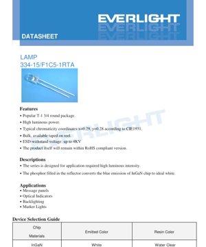
1. Product Overview
This document details the specifications for a high-luminosity white LED lamp. The device is housed in a popular T-1 3/4 round package, making it suitable for a wide range of indicator and illumination applications. The core technology involves an InGaN chip whose blue emission is converted to white light by a phosphor layer within the reflector. Key features include high luminous power output, typical chromaticity coordinates targeting a white point, and compliance with RoHS directives. The device is also designed with electrostatic discharge (ESD) protection, withstanding voltages up to 4KV.
2. Technical Parameter Deep-Dive
2.1 Absolute Maximum Ratings
The device's operational limits are defined under specific ambient conditions (Ta=25°C). The continuous forward current (IF) is rated at 30 mA, with a peak forward current (IFP) of 100 mA permissible under pulsed conditions (duty cycle 1/10 at 1 kHz). The maximum reverse voltage (VR) is 5 V. The operating temperature range (Topr) spans from -40°C to +85°C, while storage can occur between -40°C and +100°C. The device can withstand a soldering temperature (Tsol) of 260°C for 5 seconds. The total power dissipation (Pd) is limited to 110 mW. A Zener diode is integrated for protection, with a maximum reverse current (Iz) of 100 mA.
2.2 Electro-Optical Characteristics
Under standard test conditions (Ta=25°C, IF=20mA), the forward voltage (VF) ranges from a minimum of 2.8V to a maximum of 3.6V. The Zener reverse voltage (Vz) is typically 5.2V at Iz=5mA. The reverse current (IR) is guaranteed to be below 50 µA at VR=5V. The primary optical parameter, luminous intensity (IV), has a wide range from 4500 mcd (min) to 9000 mcd (max), with a typical viewing angle (2θ1/2) of 50 degrees. The typical chromaticity coordinates are x=0.29, y=0.28 according to the CIE 1931 standard.
3. Binning System Explanation
3.1 Luminous Intensity Binning
The LEDs are sorted into bins based on their measured luminous intensity at 20mA. The bin codes and their corresponding ranges are: Bin R (4500 - 5650 mcd), Bin S (5650 - 7150 mcd), and Bin T (7150 - 9000 mcd). A measurement uncertainty of ±10% is noted.
3.2 Forward Voltage Binning
Devices are also binned according to their forward voltage drop. The bins are: Code 0 (2.8 - 3.0V), Code 1 (3.0 - 3.2V), Code 2 (3.2 - 3.4V), and Code 3 (3.4 - 3.6V). The measurement uncertainty for voltage is ±0.1V.
3.3 Color Binning (Chromaticity)
The CIE chromaticity diagram and associated table define specific color ranks (A1, A0, B3, B4, B5, B6, C0). Each rank is defined by a quadrilateral area on the CIE 1931 (x,y) coordinate chart. These ranks group LEDs with similar perceived white color, covering a correlated color temperature (CCT) range from approximately 4600K to over 22000K as indicated on the diagram. The measurement uncertainty for color coordinates is ±0.01.
4. Performance Curve Analysis
The datasheet provides several characteristic curves that illustrate device behavior under varying conditions.
- Relative Intensity vs. Wavelength: Shows the spectral power distribution of the white light output, which is a broad spectrum resulting from the blue LED and phosphor combination.
- Forward Current vs. Forward Voltage (IV Curve): Depicts the non-linear relationship between current and voltage, essential for designing current-limiting circuits.
- Relative Intensity vs. Forward Current: Demonstrates how light output increases with drive current, typically showing a sub-linear relationship at higher currents due to efficiency droop and heating.
- Forward Current vs. Ambient Temperature: Shows the derating of the maximum allowable forward current as ambient temperature increases, critical for thermal management.
- Chromaticity Coordinate vs. Forward Current: Illustrates how the color point (x,y) may shift slightly with changes in drive current.
- Relative Intensity vs. Angular Displacement: A polar plot representing the spatial radiation pattern or viewing angle of the LED.
5. Mechanical and Package Information
The LED uses a standard T-1 3/4 (5mm) round package with two axial leads. The detailed dimensioned drawing specifies the overall length, lead diameter, lens shape, and seating plane. Key notes include: all dimensions are in millimeters, lead spacing is measured at the package exit point, and the maximum protrusion of resin under the flange is 1.5mm. The package is water clear.
6. Soldering and Assembly Guidelines
6.1 Lead Forming
If leads need to be bent, it must be done at a point at least 3mm from the base of the epoxy bulb. Forming should always occur before soldering. Stress on the package during forming must be avoided to prevent damage or breakage. Lead cutting should be performed at room temperature. When mounting to a PCB, holes must align perfectly with the LED leads to avoid mounting stress.
6.2 Storage
Recommended storage conditions are 30°C or less and 70% relative humidity or less. The storage life is limited to 3 months under these conditions. For longer storage (up to one year), the devices should be kept in a sealed container with a nitrogen atmosphere and desiccant.
6.3 Soldering Process
Soldering must be performed carefully, maintaining a minimum distance of 3mm from the solder joint to the epoxy bulb. Recommended conditions are:
Hand Soldering: Iron tip temperature max 300°C (30W max), soldering time max 3 seconds.
Wave/DIP Soldering: Preheat temperature max 100°C (60 sec max), solder bath temperature max 260°C for 5 seconds.
7. Packaging and Ordering Information
7.1 Packaging
The LEDs are packed in moisture-resistant and anti-static materials. The typical packing flow is: LEDs are placed in an anti-static bag (200-500 pieces per bag). Five bags are placed into an inner carton. Ten inner cartons are packed into an outside carton.
7.2 Labeling
Labels include fields for Customer Part Number (CPN), Production Number (P/N), Packing Quantity (QTY), Binning Codes for Luminous Intensity and Forward Voltage (CAT), Color Rank (HUE), Reference (REF), and Lot Number (LOT No.).
7.3 Part Number Designation
The part number follows the structure: 334-15/F1 C5-□ □ □ □. The blank spaces correspond to specific codes for Color Group, Luminous Intensity Bin, and Voltage Group, allowing precise selection of performance characteristics.
8. Application Suggestions
8.1 Typical Applications
The high luminous intensity makes this LED suitable for message panels, optical indicators, backlighting applications, and marker lights where high visibility is required.
8.2 Design Considerations
- Current Drive: Always use a constant current source or a current-limiting resistor in series with the LED. Operate at or below the recommended 20mA for standard brightness or 30mA for maximum, considering thermal derating.
- Thermal Management: While the package is not designed for high-power dissipation, ensuring adequate ventilation and avoiding operation above the maximum junction temperature is crucial for longevity, especially when driven at higher currents or in high ambient temperatures.
- ESD Protection: Although the device has built-in ESD protection (4KV), standard ESD handling precautions during assembly are still recommended.
- Optical Design: The 50-degree viewing angle provides a broad emission pattern. For focused light, secondary optics (lenses) may be required.
9. Technical Comparison and Differentiation
This LED's primary advantages in its class (T-1 3/4 white LED) are its very high luminous intensity (up to 9000 mcd) and the availability of tight electrical and color binning. The integrated Zener diode for reverse voltage protection is a notable feature that can simplify circuit design in environments prone to voltage transients. The detailed binning system allows designers to select parts for consistent brightness and color in their applications, reducing the need for post-calibration.
10. Frequently Asked Questions (Based on Technical Parameters)
Q: What is the purpose of the different bin codes?
A: Binning ensures consistency. Luminous Intensity bins (R, S, T) guarantee a minimum brightness. Voltage bins (0-3) help predict power consumption and simplify driver design. Color bins (A1-C0) ensure a uniform white color appearance across multiple LEDs in an assembly.
Q: Can I drive this LED at 30mA continuously?
A: Yes, 30mA is the absolute maximum continuous rating at 25°C. However, you must consult the derating curve (Forward Current vs. Ambient Temperature). At higher ambient temperatures, the maximum allowable continuous current decreases to prevent overheating and premature failure.
Q: How do I interpret the CIE chromaticity diagram for this LED?
A: The black body locus and CCT lines are provided for reference. The colored quadrilaterals (A1, A0, etc.) are the acceptable color ranges for each bin. LEDs are tested and sorted into these areas. A lower CCT (e.g., near B3/B4) indicates a warmer white, while a higher CCT (e.g., near C0) indicates a cooler, bluer white.
11. Practical Use Case
Scenario: Designing a High-Visibility Status Indicator Panel.
An engineer is designing an industrial control panel that requires bright, consistent white status indicators visible under high ambient light. By selecting LEDs from the same luminous intensity bin (e.g., Bin T for maximum brightness) and the same color bin (e.g., B4 for a neutral white), they ensure uniform appearance and brightness across all indicators. The 50-degree viewing angle provides good visibility from various angles. The engineer implements a simple driver circuit using a 5V supply and a current-limiting resistor calculated for ~20mA, ensuring operation within specifications. The integrated Zener diode protects the LEDs from accidental reverse polarity during maintenance.
12. Operating Principle Introduction
This is a phosphor-converted white LED. The core is a semiconductor chip made of Indium Gallium Nitride (InGaN) that emits blue light when forward biased (electroluminescence). This blue light is not emitted directly. Instead, it strikes a phosphor coating (typically Yttrium Aluminum Garnet doped with Cerium, or YAG:Ce) suspended in the epoxy resin of the package. The phosphor absorbs a portion of the blue photons and re-emits light across a broad spectrum in the yellow region. The combination of the remaining unabsorbed blue light and the broad yellow emission from the phosphor mixes to produce light that appears white to the human eye. The specific ratios of blue to yellow, and the exact phosphor composition, determine the correlated color temperature (CCT) and color rendering properties of the white light.
13. Technology Trends
The technology described represents a mature stage of phosphor-converted white LED development. Ongoing trends in the broader LED industry include:
Increased Efficiency: Continued improvements in internal quantum efficiency of the blue InGaN chip and phosphor conversion efficiency (higher lumen-per-watt output).
Color Quality: Development of multi-phosphor blends (e.g., adding red phosphors) to improve the Color Rendering Index (CRI), achieving more natural and saturated color reproduction, though this datasheet specifies a simpler single-phosphor system.
Package Miniaturization: While the T-1 3/4 remains popular, many new applications are moving towards surface-mount device (SMD) packages like 2835 or 3030 for better manufacturability and thermal performance.
Smart and Connected Lighting: Integration of control electronics directly with LED packages is a growing trend, though this product is a discrete, driver-less component.
This particular device focuses on delivering high luminous intensity within a classic through-hole package, a requirement that remains stable for many legacy and specific high-brightness indicator applications.
LED Specification Terminology
Complete explanation of LED technical terms
Photoelectric Performance
| Term | Unit/Representation | Simple Explanation | Why Important |
|---|---|---|---|
| Luminous Efficacy | lm/W (lumens per watt) | Light output per watt of electricity, higher means more energy efficient. | Directly determines energy efficiency grade and electricity cost. |
| Luminous Flux | lm (lumens) | Total light emitted by source, commonly called "brightness". | Determines if the light is bright enough. |
| Viewing Angle | ° (degrees), e.g., 120° | Angle where light intensity drops to half, determines beam width. | Affects illumination range and uniformity. |
| CCT (Color Temperature) | K (Kelvin), e.g., 2700K/6500K | Warmth/coolness of light, lower values yellowish/warm, higher whitish/cool. | Determines lighting atmosphere and suitable scenarios. |
| CRI / Ra | Unitless, 0–100 | Ability to render object colors accurately, Ra≥80 is good. | Affects color authenticity, used in high-demand places like malls, museums. |
| SDCM | MacAdam ellipse steps, e.g., "5-step" | Color consistency metric, smaller steps mean more consistent color. | Ensures uniform color across same batch of LEDs. |
| Dominant Wavelength | nm (nanometers), e.g., 620nm (red) | Wavelength corresponding to color of colored LEDs. | Determines hue of red, yellow, green monochrome LEDs. |
| Spectral Distribution | Wavelength vs intensity curve | Shows intensity distribution across wavelengths. | Affects color rendering and quality. |
Electrical Parameters
| Term | Symbol | Simple Explanation | Design Considerations |
|---|---|---|---|
| Forward Voltage | Vf | Minimum voltage to turn on LED, like "starting threshold". | Driver voltage must be ≥Vf, voltages add up for series LEDs. |
| Forward Current | If | Current value for normal LED operation. | Usually constant current drive, current determines brightness & lifespan. |
| Max Pulse Current | Ifp | Peak current tolerable for short periods, used for dimming or flashing. | Pulse width & duty cycle must be strictly controlled to avoid damage. |
| Reverse Voltage | Vr | Max reverse voltage LED can withstand, beyond may cause breakdown. | Circuit must prevent reverse connection or voltage spikes. |
| Thermal Resistance | Rth (°C/W) | Resistance to heat transfer from chip to solder, lower is better. | High thermal resistance requires stronger heat dissipation. |
| ESD Immunity | V (HBM), e.g., 1000V | Ability to withstand electrostatic discharge, higher means less vulnerable. | Anti-static measures needed in production, especially for sensitive LEDs. |
Thermal Management & Reliability
| Term | Key Metric | Simple Explanation | Impact |
|---|---|---|---|
| Junction Temperature | Tj (°C) | Actual operating temperature inside LED chip. | Every 10°C reduction may double lifespan; too high causes light decay, color shift. |
| Lumen Depreciation | L70 / L80 (hours) | Time for brightness to drop to 70% or 80% of initial. | Directly defines LED "service life". |
| Lumen Maintenance | % (e.g., 70%) | Percentage of brightness retained after time. | Indicates brightness retention over long-term use. |
| Color Shift | Δu′v′ or MacAdam ellipse | Degree of color change during use. | Affects color consistency in lighting scenes. |
| Thermal Aging | Material degradation | Deterioration due to long-term high temperature. | May cause brightness drop, color change, or open-circuit failure. |
Packaging & Materials
| Term | Common Types | Simple Explanation | Features & Applications |
|---|---|---|---|
| Package Type | EMC, PPA, Ceramic | Housing material protecting chip, providing optical/thermal interface. | EMC: good heat resistance, low cost; Ceramic: better heat dissipation, longer life. |
| Chip Structure | Front, Flip Chip | Chip electrode arrangement. | Flip chip: better heat dissipation, higher efficacy, for high-power. |
| Phosphor Coating | YAG, Silicate, Nitride | Covers blue chip, converts some to yellow/red, mixes to white. | Different phosphors affect efficacy, CCT, and CRI. |
| Lens/Optics | Flat, Microlens, TIR | Optical structure on surface controlling light distribution. | Determines viewing angle and light distribution curve. |
Quality Control & Binning
| Term | Binning Content | Simple Explanation | Purpose |
|---|---|---|---|
| Luminous Flux Bin | Code e.g., 2G, 2H | Grouped by brightness, each group has min/max lumen values. | Ensures uniform brightness in same batch. |
| Voltage Bin | Code e.g., 6W, 6X | Grouped by forward voltage range. | Facilitates driver matching, improves system efficiency. |
| Color Bin | 5-step MacAdam ellipse | Grouped by color coordinates, ensuring tight range. | Guarantees color consistency, avoids uneven color within fixture. |
| CCT Bin | 2700K, 3000K etc. | Grouped by CCT, each has corresponding coordinate range. | Meets different scene CCT requirements. |
Testing & Certification
| Term | Standard/Test | Simple Explanation | Significance |
|---|---|---|---|
| LM-80 | Lumen maintenance test | Long-term lighting at constant temperature, recording brightness decay. | Used to estimate LED life (with TM-21). |
| TM-21 | Life estimation standard | Estimates life under actual conditions based on LM-80 data. | Provides scientific life prediction. |
| IESNA | Illuminating Engineering Society | Covers optical, electrical, thermal test methods. | Industry-recognized test basis. |
| RoHS / REACH | Environmental certification | Ensures no harmful substances (lead, mercury). | Market access requirement internationally. |
| ENERGY STAR / DLC | Energy efficiency certification | Energy efficiency and performance certification for lighting. | Used in government procurement, subsidy programs, enhances competitiveness. |