Table of Contents
- 1. Product Overview
- 1.1 Core Features and Advantages
- 1.2 Target Applications
- 2. Detailed Technical Specifications
- 2.1 Absolute Maximum Ratings
- 2.2 Photoelectric Characteristics
- 3. Binning System Description
- 3.1 Radiation Intensity Grading
- 4. Performance Curve Analysis
- 4.1 Forward Current vs. Ambient Temperature Relationship
- 4.2 Spectral Distribution
- 4.3 Relationship Between Radiant Intensity and Forward Current
- 4.4 Relationship between Relative Radiant Intensity and Angular Displacement
- 5. Mechanical and Packaging Information
- 5.1 Package Dimensions
- 5.2 Polarity Identification
- 6. Welding and Assembly Guide
- 6.1 Pin Forming
- 6.2 Storage Conditions
- 6.3 Welding Recommendations
- 6.4 Cleaning
- 6.5 Thermal Management
- 7. Packaging and Ordering Information
- 7.1 Label Specifications
- 7.2 Packaging Specifications
- 8. Application Design Considerations
- 8.1 Drive Circuit Design
- 8.2 Optical Design and Alignment
- 8.3 Interference and Noise Immunity
- 9. Technical Comparison and Positioning
- 10. FAQ (Based on Technical Specifications)
- 10.1 What is the difference between Continuous Current (IF) and Peak Current (IFP)?
- 10.2 How to choose the correct bin (N, P, Q, R)?
- 10.3 Why is the soldering distance (3mm from the lamp) so important?
- 11. Design and Use Case Studies
- 11.1 Case: Enhancing the Range of Consumer Infrared Remote Controls
- 12. Working Principle
- 13. Technology Trends
1. Product Overview
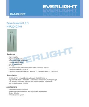
HIR204C/H0 is a high-intensity infrared emitting diode, housed in a 3.0mm water-clear transparent plastic package. It is specifically designed for applications requiring reliable infrared emission with specific spectral characteristics.
1.1 Core Features and Advantages
This device offers several key advantages for infrared system design:
- High reliability:Designed for stable performance and long service life.
- High Radiation Intensity:Provides powerful infrared output, suitable for medium-range applications.
- Peak Wavelength:The typical peak emission wavelength (λp) is 850 nm, which is a common standard for many infrared receivers and sensors.
- Low forward voltage:The typical value is 1.45V at 20mA current, which helps reduce the power consumption of the driving circuit.
- Environmental compliance:产品为无铅设计,符合欧盟REACH法规,并满足无卤素要求(Br < 900ppm, Cl < 900ppm, Br+Cl < 1500ppm)。产品本身符合RoHS规范。
- Standard Pin Pitch:Utilizes a 2.54mm (0.1 inch) pin pitch, compatible with standard prototype boards and PCB layouts.
1.2 Target Applications
The spectrum of this infrared LED matches that of common phototransistors, photodiodes, and infrared receiver modules, making it suitable for various systems, including:
- Free-space transmission systems for data or signal communication.
- Infrared remote control device requiring higher power output for longer distance or obstacle penetration.
- Smoke detector utilizing infrared beam for particulate matter detection.
- Other general infrared application systems, such as object sensing, proximity detection, and industrial automation.
2. Detailed Technical Specifications
2.1 Absolute Maximum Ratings
These ratings define the limits beyond which permanent damage to the device may occur. Operation under these conditions is not guaranteed.
- Continuous Forward Current (IF):100 mA
- Peak Forward Current (IFP):1.0 A. This rating applies to pulse conditions with a pulse width ≤ 100μs and a duty cycle ≤ 1%.
- Reverse Voltage (VR):5 V
- Operating Temperature (Topr):-40°C to +85°C
- Storage Temperature (Tstg):-40°C to +85°C
- Soldering Temperature (Tsol):Maximum 260°C, duration not exceeding 5 seconds.
- Power Dissipation (Pd):150 mW in free air at an ambient temperature of 25°C or less.
2.2 Photoelectric Characteristics
These parameters are measured at an ambient temperature (Ta) of 25°C, defining the typical performance of the device.
- Radiant intensity (Ie):Measures the infrared power emitted per unit solid angle.
- When driven at a forward current (IF) of 20mA, the typical value is 20 mW/sr.
- Under pulse conditions (IF=100mA, pulse width ≤100μs, duty cycle ≤1%), the typical radiant intensity is 40 mW/sr.
- Peak wavelength (λp):At IF=20mA, it is 850 nm (typical). This is the wavelength at which the emission intensity is highest.
- Spectral Bandwidth (Δλ):At IF=20mA, it is 45 nm (typical). This defines the range of emission wavelengths centered on the peak.
- Forward Voltage (VF):
- At IF=20mA, it is 1.45V (typical), 1.65V (maximum).
- Under pulse conditions at IF=100mA, it is 1.80V (typical), 2.40V (maximum).
- Reverse Current (IR):Maximum 10 μA when a reverse voltage (VR) of 5V is applied.
- Viewing Angle (2θ1/2):40 degrees (typical) at IF=20mA. This is the full angle at which the radiant intensity drops to half of its maximum (on-axis) value.
Measurement Tolerance:Forward Voltage: ±0.1V; Radiant Intensity: ±10%; Peak Wavelength: ±1.0nm.
3. Binning System Description
HIR204C/H0 provides different performance levels or "bins", primarily based on radiant intensity. This allows designers to select a device that meets the specific output requirements of their application.
3.1 Radiation Intensity Grading
Binning is defined under standard test conditions at IF = 20mA. The unit of radiant intensity is mW/sr.
- N Bin:Minimum 11.0, Maximum 17.6
- P grade:Minimum 15.0, Maximum 24.0
- Q grade:Minimum value 21.0, maximum value 34.0
- R gear:Minimum value 30.0, maximum value 48.0
Selecting a higher grade (e.g., grade R versus grade N) ensures a higher minimum guaranteed radiated output, which in application can translate to longer range or stronger signal strength.
4. Performance Curve Analysis
The datasheet provides several characteristic curves illustrating the device's behavior under different conditions. Understanding these is crucial for robust circuit design.
4.1 Forward Current vs. Ambient Temperature Relationship
This curve shows the derating of the maximum allowable continuous forward current as the ambient temperature increases. At 25°C, the maximum is 100mA. As temperature rises, this maximum current must be reduced to prevent exceeding the device's power dissipation limits and causing thermal damage. The curve typically shows a linear decrease from 100mA at 25°C to a lower value at 85°C.
4.2 Spectral Distribution
This chart plots the relationship between relative radiant intensity and wavelength. It visually confirms the peak wavelength (λp) of 850nm and the spectral bandwidth (Δλ) of approximately 45nm. The curve typically exhibits a Gaussian shape, centered at 850nm.
4.3 Relationship Between Radiant Intensity and Forward Current
This is a key design curve. It shows that radiant intensity (Ie) increases with forward current (IF), but the relationship is not perfectly linear, especially at higher currents. There is a point of diminishing returns where increasing the current yields less additional light output but generates significantly more heat. Designers typically drive the LED at or below the recommended continuous current (20mA or 100mA pulse) based on this curve and thermal considerations.
4.4 Relationship between Relative Radiant Intensity and Angular Displacement
This polar plot illustrates the spatial emission pattern of the LED. It shows how the intensity decreases as you move away from the central axis (0°). The 40° "viewing angle" is defined as the point where the intensity drops to 50% of the axial value. This information is crucial for optical design, determining beam coverage, and aligning the LED with a receiver.
5. Mechanical and Packaging Information
5.1 Package Dimensions
The LED uses a standard 3.0mm round package. The detailed mechanical drawing in the datasheet provides all key dimensions, including:
- The total diameter and height of the epoxy lens.
- Pin diameter and length.
- Distance from the lens bottom to the pin bend.
- Mounting plane.
General tolerances:Unless otherwise specified, dimensional tolerance is ±0.25mm. PCB hole layout and mechanical fit must refer to the precise drawing.
5.2 Polarity Identification
<>封装通常使用边缘的平面或较长的引脚来表示阴极(负极)。规格书图纸将明确指示阳极和阴极。在电路组装过程中必须注意正确的极性。6. Welding and Assembly Guide
Proper handling is crucial for maintaining device reliability and performance.
6.1 Pin Forming
- Bending must be performed at a location at least 3mm from the bottom of the epoxy bulb.
- AlwaysSolder componentsBefore
- Form leads. Avoid applying stress to the LED package or its base during forming, as this may damage internal connections or crack the epoxy.
- Cut the pins at room temperature. High-temperature cutting may lead to failure.
- Ensure perfect alignment between the PCB holes and the LED pins to avoid installation stress.
6.2 Storage Conditions
- Recommended storage conditions after receipt: temperature ≤ 30°C, relative humidity ≤ 70%.
- The shelf life under these conditions is 3 months.
- For longer storage (up to 1 year), place the device in a sealed container filled with nitrogen and containing a desiccant.
- Once the original packaging is opened, use the component within 24 hours.
- Avoid rapid temperature changes in humid environments to prevent condensation.
6.3 Welding Recommendations
The solder joint must be at least 3mm away from the epoxy resin bulb.
- Hand soldering:Soldering iron tip temperature ≤ 300°C (suitable for a maximum 30W iron). Soldering time per pin ≤ 3 seconds.
- Wave soldering / Dip soldering:Preheat temperature ≤ 100°C, time ≤ 60 seconds. Solder bath temperature ≤ 260°C, time ≤ 5 seconds.
- General rules:
- Avoid applying stress to the leads during and after soldering while the device is still hot.
- Do not perform more than one dip soldering/hand soldering.
- After soldering, protect the LED from mechanical shock/vibration until it cools to room temperature.
- Avoid rapid cooling processes.
- Always use the lowest effective soldering temperature and time.
6.4 Cleaning
- If cleaning is required, use isopropyl alcohol at room temperature for no more than one minute. Air dry at room temperature.
- Avoid ultrasonic cleaning.If absolutely necessary, extensive pre-qualification is required to ensure that specific ultrasonic power and assembly conditions do not damage the LED chip or bonding wires.
6.5 Thermal Management
Although this specification does not list specific thermal resistance values in detail, it emphasizes the importance of thermal management. The 150mW power dissipation (Pd) rating applies to a free-air environment at 25°C. In practical applications, especially when driven at higher currents or in enclosed spaces, the LED junction temperature will increase. This reduces luminous efficacy and service life. Designers must consider heat dissipation, PCB copper area, and environmental conditions during the application design phase to ensure the LED operates within safe temperature limits.
7. Packaging and Ordering Information
7.1 Label Specifications
The label on the packaging contains key information for traceability and identification:
- CPN:Customer Product Number
- P/N:Product number (e.g., HIR204C/H0)
- QTY:Quantity in package
- CAT:Luminous intensity grade (bin code, e.g. N, P, Q, R)
- HUE:Dominant Wavelength Grade
- REF:Forward Voltage Grade
- LOT No:Production Batch Number
- X:Production Month
- REF:Label Reference Number
7.2 Packaging Specifications
- Primary Packaging:Antistatic bag.
- Secondary packaging:Inner box.
- Tertiary packaging:Outer Carton.
- Standard Packing Quantity:
- 200 to 1000 pieces per antistatic bag.
- Ana shigar da jakuna 5 a cikin akwati na ciki 1.
- Ana shigar da akwatunan ciki 10 a cikin babban akwati 1.
8. Application Design Considerations
8.1 Drive Circuit Design
To drive an LED, a current-limiting circuit must be used. For basic applications, a simple series resistor is often sufficient. The resistor value (R) can be calculated using Ohm's Law: R = (Supply Voltage - Vf) / If. For example, with a supply voltage of 5V, Vf of 1.45V, and a desired If of 20mA: R = (5 - 1.45) / 0.02 = 177.5Ω. A standard 180Ω resistor would be suitable. For pulsed operation at higher currents (e.g., 100mA), it is recommended to use a transistor or a dedicated LED driver IC to provide the necessary current pulses.
8.2 Optical Design and Alignment
A 40-degree viewing angle provides a fairly wide beam. For longer distances or focused applications, a lens can be added in front of the LED. Conversely, for very wide coverage, multiple LEDs may be necessary. Precise mechanical alignment with the receiving sensor (phototransistor, infrared receiver module) is crucial for achieving optimal system performance. The spatial emission pattern curve should be referenced to understand signal strength at off-axis angles.
8.3 Interference and Noise Immunity
Infrared systems can be susceptible to ambient light noise, particularly from sunlight and incandescent lamps containing infrared components. Mitigation strategies include:
- Using modulated infrared signals (e.g., 38kHz carrier) and receivers tuned to the same frequency.
- Add an optical filter on the receiver side that blocks visible light but transmits 850nm infrared light.
- Physically shield the LED and receiver pair from direct ambient light sources.
9. Technical Comparison and Positioning
The HIR204C/H0 occupies a specific position in the infrared LED market. Compared to smaller SMD infrared LEDs, it offers higher potential radiant output due to its larger chip size and package, making it suitable for applications requiring higher power. Compared to larger, dedicated high-power infrared emitters, it is more compact and easier to drive with simple circuitry. Its 850nm wavelength is the most common, ensuring broad compatibility with receivers. Key differentiating factors include its clear package (no tint), standard 2.54mm pin spacing for easy prototyping, and a well-defined binning structure to ensure output consistency.
10. FAQ (Based on Technical Specifications)
10.1 What is the difference between Continuous Current (IF) and Peak Current (IFP)?
Continuous Forward Current (IF=100mA)It is the maximum DC current that can be passed through the LED indefinitely without causing damage, assuming the thermal limits are observed.Peak Forward Current (IFP=1.0A)It is the maximum current allowed only under very short pulse conditions (pulse width ≤100μs, duty cycle ≤1%). This allows for brief, high-intensity light pulses in applications like remote controls, but the average power must remain within the device's power dissipation limits.
10.2 How to choose the correct bin (N, P, Q, R)?
Zaɓi bisa mafi ƙarancin ƙarfin haske da ake buƙata a tazara da aiki da kuma a cikin yanayi mafi muni (misali, ƙarancin wutar lantarki, zafi mai zafi). Idan lissafin ƙirarku ya nuna cewa kuna buƙatar aƙalla 18 mW/sr, dole ne ku zaɓi ƙimar Q (matsakaicin ƙima 21.0) ko ƙimar R (matsakaicin ƙima 30.0). Ƙimar N (matsakaicin ƙima 11.0) ba ta da tabbacin aiki. Zaɓar ƙima mafi girma yana ba da ƙarin gurbin ƙira.
10.3 Why is the soldering distance (3mm from the lamp) so important?
Epoxy resin forming the lens and metal pins have different coefficients of thermal expansion. Applying high soldering heat too close to the epoxy resin can cause thermal stress, potentially leading to microcracks in the epoxy or damage to the internal die attach. These cracks may later allow moisture ingress, leading to early failure. A 3mm distance allows heat to dissipate along the pins before reaching the sensitive package.
11. Design and Use Case Studies
11.1 Case: Enhancing the Range of Consumer Infrared Remote Controls
Scenario:A designer is developing a universal remote control that needs to operate reliably at distances up to 10 meters in a typical living room, even at slight angles.
Design Selection Using HIR204C/H0:
- Drive current:Instead of using the typical 20mA continuous current, the designers employed a pulsed drive circuit. They pulsed the LED with a current of 100mA and a very short duty cycle (e.g., 0.5%) to generate high-intensity pulses, leveraging the IFP rating. This significantly increased the peak optical power, thereby enhancing the effective range.
- Gear Selection:To ensure consistent performance across all manufacturing units and account for battery voltage drop, designers specified the R-grade LED. This guarantees a higher minimum output even at the end of the battery's life.
- Layout and Lens:Two LEDs are placed slightly apart and angled relative to each other to create a wider effective beam pattern, increasing the chance of hitting the receiver from different angles. A simple, low-cost plastic lens cap is used on the LEDs to slightly collimate the beam for better directionality.
- Thermal Considerations:Due to the very low duty cycle (0.5%), the average power is small (100mA * 1.65V * 0.005 = 0.825mW), well below the 150mW Pd rating. No special heat dissipation measures are required on the PCB.
This method demonstrates how understanding the datasheet's pulse ratings, binning, and thermal parameters can enable an optimized, cost-effective design for demanding applications.
12. Working Principle
The operating principle of an Infrared Light Emitting Diode (IR LED) is the same as that of a standard visible LED, but it uses different semiconductor materials to produce light in the infrared spectrum. The HIR204C/H0 uses a Gallium Aluminum Arsenide (GaAlAs) chip. When a forward voltage is applied across the LED's P-N junction, electrons and holes recombine in the semiconductor's active region. This recombination process releases energy in the form of photons. The specific bandgap energy of the GaAlAs material determines the wavelength of these photons, which in this case is centered around 850 nm, located in the near-infrared region and invisible to the human eye. The water-clear epoxy encapsulation does not filter or tint the light, allowing the maximum amount of generated infrared radiation to escape.
13. Technology Trends
Kızılötesi verici alanı sürekli gelişmektedir. Sektörde gözlemlenebilen genel eğilimler şunları içerir:
- Verimlilik Artışı:Develop new semiconductor epitaxial structures to achieve higher radiant intensity (mW/sr) at the same input current (mA), thereby improving overall system energy efficiency.
- Miniaturization:While through-hole packages like 3mm remain popular for their robustness and ease of use, there is a strong trend toward Surface-Mount Device (SMD) packages (e.g., 0805, 0603), suitable for automated assembly and space-constrained designs, such as in smartphones (for proximity sensors) and miniature IoT devices.
- Wavelength Diversification:Although 850nm and 940nm dominate, the use of other wavelengths in specific applications is growing, such as 810nm for medical devices or specific narrow bands for gas sensing.
- Integration:Combining infrared LEDs with drive circuits, modulators, and even photodetectors into a single package to create smarter, easier-to-use "sensor modules."
- Enhanced reliability data:Modern datasheets increasingly provide more detailed lifetime and reliability data (e.g., L70, L50 data under various stress conditions) to support the design of automotive, industrial, and medical applications where long-term performance is critical.
The HIR204C/H0 represents a mature, reliable, and well-known component that benefits from these ongoing material and manufacturing advancements, ensuring its continued relevance in a wide range of electronic designs.
Detailed Explanation of LED Specification Terminology
Complete Explanation of LED Technical Terminology
I. Core Indicators of Photoelectric Performance
| Terminology | Unit/Representation | Popular Explanation | Why It Is Important |
|---|---|---|---|
| Luminous Efficacy | lm/W | The luminous flux emitted per watt of electrical power; higher values indicate greater energy efficiency. | Directly determines the energy efficiency rating and electricity cost of the luminaire. |
| Luminous Flux | lm (lumen) | The total amount of light emitted by a light source, commonly known as "brightness". | Determines whether a luminaire is bright enough. |
| Viewing Angle | ° (degrees), such as 120° | The angle at which light intensity drops to half determines the beam width. | Affects the illumination range and uniformity. |
| Color Temperature (CCT) | K (Kelvin), e.g., 2700K/6500K | The warmth or coolness of light color; lower values are yellowish/warm, higher values are whitish/cool. | Determining the lighting atmosphere and applicable scenarios. |
| Color Rendering Index (CRI / Ra) | Unitless, 0–100 | The ability of a light source to restore the true color of an object, Ra≥80 is recommended. | Affects color authenticity, used in high-demand places such as shopping malls and art galleries. |
| SDCM | MacAdam ellipse steps, e.g., "5-step" | A quantitative indicator of color consistency; the smaller the step number, the better the color consistency. | Ensure no color difference among the same batch of luminaires. |
| Dominant Wavelength | nm (nanometer), misali 620nm (ja) | Rangi ya LED zenye rangi zinazolingana na thamani ya urefu wa wimbi. | Kuamua rangi ya LED moja kama nyekundu, manjano, kijani, n.k. |
| Spectral Distribution | Wavelength vs. Intensity Curve | Display the intensity distribution of light emitted by the LED across various wavelengths. | Affects color rendering and color quality. |
II. Electrical Parameters
| Terminology | Symbol | Popular Explanation | Design Considerations |
|---|---|---|---|
| Forward Voltage | Vf | The minimum voltage required to light up an LED, similar to a "starting threshold". | The driving power supply voltage must be ≥ Vf, and the voltage adds up when multiple LEDs are connected in series. |
| Forward Current | If | The current value that makes the LED emit light normally. | Constant current drive is often used, as the current determines brightness and lifespan. |
| Matsakaicin ƙarfin wutar lantarki na bugun jini (Pulse Current) | Ifp | Peak current that can be sustained for a short period, used for dimming or flashing. | Pulse width and duty cycle must be strictly controlled to prevent overheating and damage. |
| Reverse Voltage | Vr | The maximum reverse voltage that an LED can withstand; exceeding it may cause breakdown. | Circuit ina buƙatar hana jujjuyawar kewayawa ko ƙarfin wutar lantarki. |
| Thermal Resistance | Rth (°C/W) | The resistance to heat transfer from the chip to the solder joint. A lower value indicates better heat dissipation. | High thermal resistance requires a stronger heat dissipation design; otherwise, the junction temperature will increase. |
| ESD Immunity | V (HBM), e.g., 1000V | The higher the value, the more resistant it is to electrostatic damage. | Anti-static measures must be implemented during production, especially for high-sensitivity LEDs. |
III. Thermal Management and Reliability
| Terminology | Key Indicators | Popular Explanation | Impact |
|---|---|---|---|
| Junction Temperature | Tj (°C) | The actual operating temperature inside the LED chip. | For every 10°C reduction, lifespan may double; excessively high temperatures cause lumen depreciation and color shift. |
| Lumen Depreciation | L70 / L80 (hours) | The time required for brightness to drop to 70% or 80% of its initial value. | Directly defines the "lifetime" of an LED. |
| Lumen Maintenance | % (e.g., 70%) | The percentage of remaining brightness after a period of use. | Characterizes the ability to maintain brightness after long-term use. |
| Color Shift | Δu′v′ or MacAdam ellipse | The degree of color change during use. | Affects the color consistency of the lighting scene. |
| Thermal Aging | Material performance degradation | Deterioration of packaging materials due to prolonged high temperatures. | May lead to decreased brightness, color shift, or open-circuit failure. |
IV. Packaging and Materials
| Terminology | Common Types | Popular Explanation | Characteristics and Applications |
|---|---|---|---|
| Packaging Type | EMC, PPA, Ceramic | The housing material that protects the chip and provides optical and thermal interfaces. | EMC tahan panas baik, biaya rendah; keramik pendinginan unggul, umur panjang. |
| Struktur chip | Face-up, Flip Chip | Chip electrode arrangement method. | Flip Chip offers better heat dissipation and higher luminous efficacy, suitable for high-power applications. |
| Phosphor coating | YAG, silicate, nitride | Covered on the blue light chip, partially converted into yellow/red light, mixed into white light. | Different phosphors affect luminous efficacy, color temperature, and color rendering. |
| Lens/Optical design | Planar, Microlens, Total Internal Reflection | Optical structures on the encapsulation surface control light distribution. | Determine the beam angle and light distribution curve. |
V. Quality Control and Binning
| Terminology | Binning Content | Popular Explanation | Purpose |
|---|---|---|---|
| Luminous Flux Grading | Codes such as 2G, 2H | Group by brightness level, each group has a minimum/maximum lumen value. | Ensure consistent brightness for the same batch of products. |
| Voltage binning | Codes such as 6W, 6X | Group by forward voltage range. | Facilitate driver matching and improve system efficiency. |
| Color binning. | 5-step MacAdam ellipse | Group by color coordinates to ensure colors fall within a minimal range. | Ensure color consistency to avoid uneven color within the same luminaire. |
| Correlated Color Temperature (CCT) Binning | 2700K, 3000K, etc. | Grouped by color temperature, each group has a corresponding coordinate range. | To meet the color temperature requirements of different scenarios. |
VI. Testing and Certification
| Terminology | Standards/Testing | Popular Explanation | Significance |
|---|---|---|---|
| LM-80 | Lumen Maintenance Test | Record brightness attenuation data under constant temperature conditions over long-term operation. | Used for estimating LED lifetime (in conjunction with TM-21). |
| TM-21 | Standard for Life Projection | Projecting lifetime under actual use conditions based on LM-80 data. | Provide scientific life prediction. |
| IESNA Standard | Illuminating Engineering Society Standard | Covers optical, electrical, and thermal testing methods. | Industry-recognized testing basis. |
| RoHS / REACH | Environmental Certification | Ensure products are free from hazardous substances (e.g., lead, mercury). | Market access requirements for entering the international market. |
| ENERGY STAR / DLC | Energy Efficiency Certification | Energy Efficiency and Performance Certification for Lighting Products. | Commonly used in government procurement and subsidy programs to enhance market competitiveness. |