Table of Contents
- 1. Product Overview
- 2. Bincike Mai zurfi na Sigogi na Fasaha
- 2.1 Absolute Maximum Ratings
- 2.2 Halayen Haske da Lantarki
- 2.2.1 Halayen Input Diode
- 2.2.2 Output Transistor Characteristics
- 2.3 Transfer Characteristics
- 3. Grading System Description
- 4. Performance Curve Analysis
- 5. Mechanical and Packaging Information
- 6. Soldering and Assembly Guide
- 7. Packaging and Ordering Information
- 8. Application Recommendations
- 8.1 Yanayin Aikace-aikace na Al'ada
- 8.2 Abubuwan da Ya Kamata a Lura da su a Zane
- 9. Kwatancen Fasaha da Bambance-bambance
- 10. Tambayoyin da ake yawan yi (bisa sigogin fasaha)
- 11. Misalan ƙira masu amfani
- 12. Hanyar aiki
- 13. Trends na fasaha
- Cikakken bayani game da kalmomin ƙayyadaddun LED
- I. Core Indicators of Photoelectric Performance
- II. Electrical Parameters
- III. Thermal Management and Reliability
- IV. Packaging and Materials
- V. Quality Control and Grading
- VI. Testing and Certification
1. Product Overview
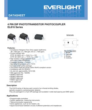
The EL816 series represents a family of industry-standard 4-pin Dual In-line Package (DIP) phototransistor optocouplers. These devices are designed to provide reliable electrical isolation and signal transmission between circuits of different potentials. Each unit integrates an infrared emitting diode, which is optically coupled to a silicon phototransistor detector, within a compact package.
Its core function is electrical isolation, which prevents ground loops, blocks high-voltage transients, and allows signal transmission between circuits with different reference grounds or voltage levels. This series is characterized by its robust construction, offering high isolation voltage and a wide range of Current Transfer Ratio (CTR) grades to meet various application needs, from simple switch detection to linear signal transmission.
2. Bincike Mai zurfi na Sigogi na Fasaha
2.1 Absolute Maximum Ratings
These ratings define the stress limits that could cause permanent damage. The device is not intended to operate under these extreme conditions.
- Input (LED Side):The maximum continuous forward current (IF) for the infrared diode is 60 mA. A brief 1 A pulse (duration of 1 µs) is permitted. The maximum reverse voltage (VR) is 6 V, emphasizing the necessity of correct polarity protection.
- Output (transistor side):The phototransistor can withstand a collector current (IC) of 50 mA and a collector-emitter voltage (VCEO) of 80 V. The lower emitter-collector voltage (VECO= 6V) indicates the asymmetry of the phototransistor junction.
- Isolation and Thermal Characteristics:A key specification is the isolation voltage (VISO) of 5000 Vrms(for 1 minute), with pins 1-2 shorted and pins 3-4 shorted during testing. The device operating temperature range is -55°C to +110°C, and it can withstand a soldering temperature of 260°C for 10 seconds.
- Power Consumption:Total device power dissipation (PTOT) is 200 mW. The input diode can dissipate 100 mW without derating up to 100°C. The output transistor is rated for 150 mW power dissipation and requires derating at a rate of 5.8 mW/°C above 80°C.
2.2 Halayen Haske da Lantarki
These parameters define the device performance under normal operating conditions (unless noted, Ta= 25°C).
2.2.1 Halayen Input Diode
- Forward Voltage (VF):The typical value is 1.2V, with a maximum of 1.4V at IF= 20 mA. This value is used to calculate the current-limiting resistor value.
- Reverse current (IR):at VR= 4V is a maximum of 10 µA, indicating the diode has good reverse characteristics.
- Input capacitance (Cin):can be as high as 250 pF, which may affect the design of high-frequency drive circuits.
2.2.2 Output Transistor Characteristics
- Dark current (ICEO):Leakage current when the LED is off at VCE= 100 nA maximum at 20V, defining the noise floor of the "off state".
- Breakdown voltage: BVCEO≥ 80V and BVECO≥ 6V, confirming the voltage blocking capability.
2.3 Transfer Characteristics
These are the most critical parameters in application design, defining the relationship between input current and output current.
- Current Transfer Ratio (CTR):This is the ratio of the output collector current (IC) to the input forward current (IF), expressed as a percentage. The EL816 series offers a wide selection of CTR grades, tested under standard conditions (for most models, IF= 5mA, VCE= 5V; for I/J/K grades, IF= 10mA). The ranges include:
- EL816: 50% to 600% (wide range, ungraded)
- EL816A: 80% to 160%
- EL816B: 130% to 260%
- EL816C: 200% to 400%
- EL816D: 300% to 600%
- EL816X: 100% to 200%
- EL816Y: 150% to 300%
- EL816I: 63% to 125% (at IF=10mA)
- EL816J: 100% to 200% (at IF=10mA)
- EL816K: 160% to 320% (at IF=10mA)
- Saturation voltage (VCE(sat)):At IF=20mA, IC=1mA, the typical value is 0.1V (maximum 0.2V). This low value is crucial for achieving a reliable 'low' logic level in digital switching applications.
- Isolation resistance and capacitance: RIO> 5×10¹⁰Ω and CIO <1.0 pF。高电阻确保漏电流最小,而低电容对于在嘈杂环境中保持高共模瞬变抗扰度(CMTI)至关重要。
- Frequency response:Cutoff frequency (fc) typically 80 kHz, defining the useful bandwidth for analog signal transmission.
- Switching speed:Under specified test conditions (Ir=2mA, Rf=100Ω), the typical rise time (tC) and fall time (tL) are 4 µs and 3 µs, respectively (each maximum 18 µs). This determines the maximum digital switching frequency.
3. Grading System Description
The EL816 series employs a precise grading system based solely on Current Transfer Ratio (CTR).
- CTR Grading:Devices are categorized into different grades (A, B, C, D, X, Y, I, J, K) based on their measured CTR at a specified test current. This allows designers to select components with a guaranteed gain range, thereby improving circuit consistency and yield. For example, selecting an EL816C (200-400%) ensures a higher minimum gain than an EL816A (80-160%), which may allow for the use of lower LED drive current or provide more output current margin.
- No Wavelength/Color Grading:Since the emitter is an infrared diode, visible light wavelength or color grading is not applicable. The phototransistor is sensitive to the infrared spectrum emitted by its matched LED.
4. Performance Curve Analysis
Although the provided text does not detail specific curves, the following analyzes the typical performance trends of such devices based on the described parameters.
- CTR vs. Forward Current (IF):CTR is not constant; it typically peaks at a specific IFand decreases at very low or very high currents. Specifying CTR at 5mA and 10mA (and at 1mA for some grades) implies this non-linearity. Designers should operate near the test conditions for predictable gain.
- CTR vs. Temperature:CTR yawanci yana da ingantaccen ma'aunin zafi mai kyau; yana raguwa yayin da zafin jiki ya tashi. Faɗin kewayon aiki na zafin jiki (-55°C zuwa +110°C) yana buƙatar la'akari da wannan raguwar a cikin ƙirar muhalli mai tsanani.
- Lokacin sauyawa da juriya na kaya (RL):An ƙayyade trda tfan auna su a cikin sharuɗɗan RL=100Ω. Gudun sauyawa yana shafar RLda kowane ƙwayar cuta mai ƙwayar cuta sosai. Ƙananan RLyawanci yana hanzarta saurin kashewa, amma yana iya ƙara yawan amfani da wutar lantarki.
- Ƙarfafawa mai kyau da yanayin zafi:Diode VFYana da coefficient na zafin jiki mara kyau, kusan 2 mV a kowane °C na raguwa. Idan aka kwatanta da dogaron zafin jiki na CTR, wannan tasiri ne na biyu.
5. Mechanical and Packaging Information
Wannan jerin yana ba da zaɓuɓɓukan kunshewa daban-daban, don dacewa da hanyoyin haɗa PCB daban-daban da buƙatun tazara.
- Nau'in DIP na yau da kullun:Kunshewar rami ta al'ada tare da tazarar fil ɗin daidaitacce.
- Nau'in zaɓi na M:Kunshewar rami mai "lanƙwasa fil ɗin fadi," tana ba da tazarar fil ɗin 0.4 inci (kusan 10.16 mm) don ƙara tazarar hawa/ɓangarorin lantarki ko dacewa da takamaiman soket.
- Nau'in zaɓi na S1:A "low-profile" surface-mount (SMD) lead form. Supplied in tape-and-reel (TU or TD) format, 1500 pieces per reel.
- S2 Option Type:Another SMD low-profile lead form with different package dimensions, supplied in tape-and-reel format, 2000 pieces per reel.
- Creepage Distance:Exceeds 7.62 mm, which is crucial for meeting safety standards for reinforced insulation under high isolation voltage.
- Device Marking:The package is marked with "EL" (manufacturer code), "816" (device number), a letter indicating the CTR grade (R), and a one-digit year code (Y) plus week number (WW).
6. Soldering and Assembly Guide
Dangane da Ƙididdiga na Gabaɗaya Mafi Girma da Zaɓuɓɓukan Kunshe.
- Zazzabi na Walda:Na'urar na iya jure zazzabin walda mai tsayin 260°C na dakika 10. Wannan ya dace da daidaitaccen lanƙwasa sake walda maras gubar (SnAgCu).
- Hancin Danshi:Ko da yake ba a bayyana a cikin taƙaitaccen ba, kayan SMD (zaɓuɓɓukan S1, S2) yawanci suna da matakin hankali ga danshi (MSL). Yana da mahimmanci a bi umarnin sarrafa masana'anta, gami da gasa idan an fallasa su cikin iskar muhalli fiye da lokacin da aka kayyade, don hana "fashewar gasa" yayin sake walda.
- Sharuɗɗan Ajiya:Kewayon zazzabin ajiya shine daga -55°C zuwa +125°C. Ya kamata a adana kayan a cikin busasshiyar muhalli mai sarrafawa.
- Recommended Pad Layout:The datasheet provides specific pad pattern recommendations for the S1 and S2 surface mount options. Using these recommendations is crucial for forming reliable solder joints and ensuring mechanical stability.
7. Packaging and Ordering Information
The part number follows the format: EL816X(Y)(Z)-FV
- X (Lead Form):S1, S2, M, or none (Standard DIP).
- Y (CTR Grade):A, B, C, D, X, Y, I, J, K, or none (ungraded).
- Z (tape and reel):TU, TD (for SMD option), or none.
- F (lead frame):F indicates iron, blank indicates copper.
- V:Optional VDE safety certification mark.
Package quantity:Through-hole components are supplied in tube packaging, with 100 pieces per tube. SMD components are supplied in tape and reel packaging: S1 with 1500 pieces per reel, S2 with 2000 pieces per reel.
8. Application Recommendations
8.1 Yanayin Aikace-aikace na Al'ada
- Programmable Logic Controller (PLC):Isolate digital I/O modules from the central processing unit and field devices.
- System Equipment and Measurement Instruments:Provide isolation in power supplies, data acquisition systems, and test equipment.
- Telecommunications Equipment:Isolate signal lines in modems, interfaces, and network equipment.
- Household Appliances:Used in control circuits of appliances such as fan heaters and washing machines to safely perform low-voltage control on components connected to the mains.
- General Signal Transmission:Any application requiring voltage level conversion between circuits or elimination of ground loops.
8.2 Abubuwan da Ya Kamata a Lura da su a Zane
- LED Current Limiting:Always use a series resistor to set IF. Calculate Rlimit= (VCC- VF) / IF. Operate near the CTR test conditions (5mA or 10mA) to obtain predictable gain.
- Output load:The load resistor (RL) on the collector affects switching speed, output swing, and power consumption. A smaller RLprovides faster turn-off speed, but results in lower output voltage swing and IC.
- Noise Immunity:For digital applications, ensure sufficient CTR margin so that the "ON state" ICcan fully saturate the transistor (VCE(sat) <0.4V),并且“关断状态”的暗电流与偏置条件相比可以忽略不计。
- Temperature Effects:Consider the degradation of CTR at high temperatures. As a rule of thumb, derate the available CTR by 0.5% to 1% for every degree Celsius above 25°C. Ensure the device remains within its power dissipation limits over the entire operating temperature range.
- High Voltage Layout:To maintain the 5000Vrmsisolation rating, the PCB layout must adhere to the creepage and clearance distances specified in safety standards (e.g., IEC 60664-1). This typically means placing slots or isolation barriers under the package.
9. Kwatancen Fasaha da Bambance-bambance
Key advantages reflected in the EL816 series specifications:
- High Isolation Voltage:5000Vrmsis a robust rating suitable for many industrial and mains-connected applications.
- Wide CTR Selection:Extensive grading (9 different grades plus an ungraded version) provides excellent design flexibility for optimizing cost versus performance.
- Extended Temperature Range:Operating temperature up to +110°C, exceeding the typical +85°C or +100°C range of many standard optocouplers, making it suitable for harsher environments.
- Package Diversity:Offers through-hole (standard and wide-body) and two low-profile SMD options, meeting the needs of both modern and traditional assembly processes.
- Compliance:The device complies with key industry standards: halogen-free (for copper lead frame versions), RoHS, EU REACH, and is certified by UL, cUL, VDE, SEMKO, NEMKO, DEMKO, FIMKO, and CQC, facilitating global market access.
10. Tambayoyin da ake yawan yi (bisa sigogin fasaha)
- Q: What are the differences between EL816 and EL816A/B/C, etc.?
A: The suffix indicates the CTR grade. EL816 is an ungraded part with a wide CTR range (50-600%). EL816A, B, C, D, X, Y, I, J, K are graded parts with tighter, guaranteed CTR ranges, allowing for more precise circuit design. - Q: Can I use it for analog signal transmission?
A: Yes, but with limitations. The typical bandwidth is 80 kHz, and CTR varies non-linearly with IFand temperature. It is suitable for low-frequency or low-precision analog isolation. For higher performance, dedicated linear optocouplers or isolation amplifiers are recommended. - Q: How to choose the appropriate CTR grade?
A: For digital switching, select a grade such that at your operating IFThe minimum CTR under the given conditions should provide sufficient ICto drive your load (e.g., pull down a logic input) with margin. For example, if you need IC> 1mA when IF> 1mA,则需要CTR > 20%。更高的等级(例如C或D)提供更大的余量。对于简单的开关检测,较低的等级(A、I)可能更具成本效益。 - 问:“爬电距离 > 7.62 mm”对我的PCB设计意味着什么?
A: Creepage distance is the shortest distance between conductive parts along the surface of insulation. To maintain the specified isolation rating, you must ensure that PCB copper traces/pads on the input and output sides maintain at least this distance (or greater according to the relevant safety standard) on the board surface under the component as well.
11. Misalan ƙira masu amfani
Scenario:Isolate a 3.3V microcontroller GPIO pin to control a 12V relay coil on a separate circuit.
- Zabi na abu:Zaɓi EL816C (CTR 200-400%) don samun ingantaccen riba mai fa'ida. Ƙirƙirar samfuri tana amfani da daidaitaccen kunshe na DIP.
- Shigar da kewayawa:Fitowar fil ɗin microcontroller shine 3.3V. VF~ 1.2V. Manufa IF= 5mA (daidaitattun sharuɗɗan gwaji).
Rlimit= (3.3V - 1.2V) / 0.005A = 420Ω. Yi amfani da daidaitaccen resistor na 470Ω. Ainihin IF≈ (3.3-1.2)/470 = 4.5mA. - Fitowar kewayawa:Relay coil operating voltage 12V, coil resistance 240Ω (requires 50mA). The IC(max)is 50mA, which is at the limit. A better design is to use the optocoupler to drive a transistor, which then drives the relay. For demonstration, assume using a small-signal relay with a 12V, 100Ω coil (120mA). The optocoupler cannot drive it directly.
Instead, configure the phototransistor as a switch to pull the base of an NPN transistor (e.g., 2N2222) low to ground. The phototransistor's collector is connected to the 12V supply via a 10kΩ pull-up resistor and to the base of the NPN. The emitter is grounded. When the LED is on, the phototransistor saturates, pulling the NPN base low, turning it off. When the LED is off, the 10kΩ resistor pulls the NPN base high, turning it on and powering the relay. A flyback diode must be placed in parallel with the relay coil. - Isolation:The 12V relay power supply and the 3.3V microcontroller power supply must be completely independent, with no common ground connection, to maintain isolation.
12. Hanyar aiki
The EL816 is an optoelectronic device. Current applied to the input side (Pin 1-Anode and 2-Cathode) causes the infrared light-emitting diode (LED) to emit photons. These photons travel across a transparent insulating gap (typically molded plastic) and illuminate the base region of a silicon NPN phototransistor on the output side (Pin 3-Emitter and 4-Collector).
Incident photons generate electron-hole pairs in the base-collector junction of the transistor, effectively acting as base current. This photogenerated current is then amplified by the transistor's current gain (hFE) , resulting in a larger collector current flowing between pins 4 and 3. The key point is that the signal is transmitted via light, not through an electrical connection, thereby providing electrical isolation between the input and output circuits. The ratio of the output collector current to the input LED current is the Current Transfer Ratio (CTR).
13. Trends na fasaha
Optocouplers with phototransistors, such as the EL816, represent a mature and cost-effective isolation technology. Current trends in the isolation component market include:
- Higher Speeds:Demand for faster digital isolators based on CMOS and RF coupling technologies for communication interfaces (USB, SPI, I2C) with speeds exceeding 100 Mbps.
- Integrated Functions:The proliferation of isolators integrating power (isoPower) or gate drivers (isolated gate drivers) within a single package continues to grow.
- Miniaturization:There is a continuous push for smaller package footprints and thinner profiles, particularly in surface-mount options, to save PCB space.
- Enhanced Reliability and Robustness:Focus is on improving Common-Mode Transient Immunity (CMTI) to withstand fast voltage spikes common in motor drives and power systems, along with extending operational lifetime and temperature range.
- Role of Optocouplers:Despite the emergence of new technologies, traditional optocouplers maintain a strong position in cost-sensitive applications, medium-to-low-speed digital isolation, and areas where high isolation voltage and proven long-term reliability are critical. Their simplicity and robustness ensure their continued relevance.
Cikakken bayani game da kalmomin ƙayyadaddun LED
Complete Interpretation of LED Technical Terminology
I. Core Indicators of Photoelectric Performance
| Terminology | Unit/Representation | Layman's Explanation | Why It Is Important |
|---|---|---|---|
| Luminous Efficacy | lm/W | The luminous flux emitted per watt of electrical power; higher values indicate greater energy efficiency. | Directly determines the energy efficiency rating of the luminaire and the electricity cost. |
| Luminous Flux | lm | Total light output from a light source, commonly known as "brightness". | Determines if a luminaire is bright enough. |
| Viewing Angle | ° (degree), e.g., 120° | The angle at which light intensity drops to half, determining the beam width. | Affects the illumination range and uniformity. |
| Yanayin zafi na launi (CCT) | K (Kelvin), kamar 2700K/6500K | Launin haske mai dumi ko sanyi, ƙananan ƙima yana karkata zuwa rawaya/dumi, babban ƙima yana karkata zuwa fari/sanyi. | Yana ƙayyade yanayin haskakawa da wurin da ya dace. |
| Ma'aunin nuna launi (CRI / Ra) | Babu raka'a, 0–100 | The ability of a light source to reproduce the true colors of objects, Ra≥80 is preferred. | Affects color fidelity, used in high-demand places such as shopping malls and art galleries. |
| Color Tolerance (SDCM) | MacAdam ellipse steps, e.g., "5-step" | A quantitative indicator of color consistency; the smaller the step number, the more consistent the color. | Ensures no color difference among the same batch of luminaires. |
| Dominant Wavelength | nm (nanometer), e.g., 620nm (red) | The wavelength value corresponding to the color of a colored LED. | Determines the hue of monochromatic LEDs such as red, yellow, and green. |
| Spectral Distribution | Wavelength vs. Intensity curve | Shows the intensity distribution of light emitted by an LED across various wavelengths. | Affects color rendering and color quality. |
II. Electrical Parameters
| Terminology | Symbol | Layman's Explanation | Design Considerations |
|---|---|---|---|
| Forward Voltage | Vf | The minimum voltage required to turn on an LED, similar to a "starting threshold". | The driving power supply voltage must be ≥ Vf; voltages add up when multiple LEDs are connected in series. |
| Forward Current | If | The current value that allows an LED to emit light normally. | Constant current drive is often used, where the current determines brightness and lifespan. |
| Maximum Pulse Current | Ifp | The peak current that can be withstood in a short time, used for dimming or flashing. | Pulse width and duty cycle must be strictly controlled, otherwise overheating damage will occur. |
| Reverse Voltage | Vr | The maximum reverse voltage that an LED can withstand; exceeding it may cause breakdown. | Reverse connection or voltage surges must be prevented in the circuit. |
| Thermal Resistance | Rth (°C/W) | The resistance to heat flow from the chip to the solder point; a lower value indicates better heat dissipation. | High thermal resistance requires a stronger heat dissipation design; otherwise, the junction temperature will increase. |
| Electrostatic Discharge Immunity (ESD Immunity) | V (HBM), e.g., 1000V | The ability to withstand electrostatic strikes; a higher value means it is less susceptible to damage from static electricity. | Anti-static measures must be implemented during production, especially for high-sensitivity LEDs. |
III. Thermal Management and Reliability
| Terminology | Maɗaukakin Ma'auni | Layman's Explanation | Tasiri |
|---|---|---|---|
| Junction Temperature | Tj(°C) | Ainihin zafin aiki a cikin guntu na LED. | Kowane raguwa na 10°C, yana iya tsawaita rayuwa sau biyu; yawan zafi yana haifar da raguwar haske da karkatar launi. |
| Lumen Depreciation | L70 / L80 (hours) | The time required for brightness to drop to 70% or 80% of its initial value. | Directly defines the "useful life" of an LED. |
| Lumen Maintenance | % (e.g., 70%) | The percentage of remaining brightness after a period of use. | Characterizes the ability to maintain brightness after long-term use. |
| Color Shift | Δu′v′ or MacAdam Ellipse | The degree of color change during use. | Affects the color consistency of the lighting scene. |
| Thermal Aging | Decline in material performance. | Degradation of packaging materials due to prolonged high temperatures. | May lead to decreased brightness, color change, or open-circuit failure. |
IV. Packaging and Materials
| Terminology | Common Types | Layman's Explanation | Characteristics and Applications |
|---|---|---|---|
| Package Types | EMC, PPA, Ceramic | The housing material that protects the chip and provides optical and thermal interfaces. | EMC offers good heat resistance and low cost; ceramic provides superior heat dissipation and long lifespan. |
| Chip Structure | Front-side, Flip Chip | Chip Electrode Layout Method. | Flip Chip offers better heat dissipation and higher luminous efficacy, suitable for high power. |
| Phosphor Coating | YAG, Silicate, Nitride | Coated on the blue LED chip, partially converting to yellow/red light, mixing to form white light. | Different phosphors affect luminous efficacy, color temperature, and color rendering. |
| Lens/Optical Design | Flat, microlens, total internal reflection | The optical structure on the package surface controls light distribution. | Determines the beam angle and light distribution curve. |
V. Quality Control and Grading
| Terminology | Grading Content | Layman's Explanation | Purpose |
|---|---|---|---|
| Luminous Flux Grading | Codes such as 2G, 2H | Grouped according to brightness level, each group has a minimum/maximum lumen value. | Ensure consistent brightness within the same batch of products. |
| Voltage Binning | Codes such as 6W, 6X | Grouping based on forward voltage range. | Facilitates driver matching and improves system efficiency. |
| Color Binning | 5-step MacAdam ellipse | Group by color coordinates to ensure colors fall within a minimal range. | Ensure color consistency to avoid color variation within the same luminaire. |
| Color temperature binning | 2700K, 3000K, etc. | Group by color temperature, each group has a corresponding coordinate range. | Meet the color temperature requirements for different scenarios. |
VI. Testing and Certification
| Terminology | Standard/Test | Layman's Explanation | Significance |
|---|---|---|---|
| LM-80 | Lumen Maintenance Test | Long-term illumination under constant temperature conditions, recording brightness attenuation data. | Used to estimate LED lifetime (combined with TM-21). |
| TM-21 | Lifetime extrapolation standard | Estimate lifetime under actual use conditions based on LM-80 data. | Provide scientific lifetime prediction. |
| IESNA standard | Illuminating Engineering Society Standard | Covers optical, electrical, and thermal test methods. | Industry-recognized testing basis. |
| RoHS / REACH | Environmental certification. | Ensures products are free from harmful substances (e.g., lead, mercury). | Market access requirements for entering international markets. |
| ENERGY STAR / DLC | Energy efficiency certification. | Energy efficiency and performance certification for lighting products. | Commonly used in government procurement and subsidy programs to enhance market competitiveness. |