Table of Contents
- 1. Product Overview
- 2. Technical Parameter Deep Dive
- 2.1 Absolute Maximum Ratings
- 2.2 Electrical & Transfer Characteristics
- 2.3 Switching Characteristics
- 3. Performance Curve Analysis
- 4. Mechanical & Package Information
- 4.1 Pin Configuration and Function
- 5. Application Guidelines
- 5.1 Typical Application Circuits
- 5.2 Design Considerations
- 6. Technical Comparison & Selection Guide
- 7. Packaging and Ordering Information
- 8. Principle of Operation
- 9. Application Scenarios
- 10. Frequently Asked Questions (FAQ)
1. Product Overview
EL045X da EL050X series su manyan gudun, transistor-output photocouplers (optocouplers) da aka tsara don keɓance siginar a cikin da'irar lantarki masu ƙarfi. Kowane na'urar tana haɗa infrared light-emitting diode (LED) wanda aka haɗa ta hanyar gani zuwa babban gudun photodetector transistor. Babban fasalin gine-gine shine keɓance haɗin da aka samar don photodiode bias da mai tarawa na transistor na fitarwa. Wannan ƙira tana haɓaka gudun sauyawa sosai ta hanyar rage ƙarfin ƙarfin tushe-taro na transistor na shigarwa idan aka kwatanta da na'urori na phototransistor couplers na al'ada. Ana ajiye na'urorin a cikin ƙaramin 8-pin Small Outline Package (SOP) wanda ya dace da daidaitaccen sawun SO-8, yana mai da su dace da aikace-aikacen da ke da ƙarancin sarari.
The core advantage of this series lies in its combination of high-speed data transmission capability (up to 1 Mbit/s) and robust electrical isolation. They offer a high common-mode transient immunity (CMTI), particularly the EL0453 variant which guarantees a minimum of 15 kV/µs, making them ideal for noisy environments like motor drives and switch-mode power supplies. The series is characterized by a wide operating temperature range, compliance with international safety and environmental standards (UL, cUL, VDE, RoHS, Halogen Free, REACH), and is available in different current transfer ratio (CTR) grades to suit various application needs.
2. Technical Parameter Deep Dive
2.1 Absolute Maximum Ratings
These ratings define the stress limits beyond which permanent damage to the device may occur. Operating the device continuously at or near these limits is not recommended.
- Input (LED Side): Maximum continuous forward current (IF) is 25 mA. It can handle a peak forward current (IFP) of 50 mA under pulsed conditions (50% duty cycle, 1ms pulse width). A very high peak transient current (IFtrans) of 1A is allowed for very short pulses (≤ 1µs, 300 pps). The maximum reverse voltage (VR) is 5V.
- Output (Detector Side): The average output current (IO(AVG)) should not exceed 8 mA, with a peak output current (IO(PK)) limit of 16 mA. The output voltage (VO) can range from -0.5V to +20V, and the supply voltage (VCC) from -0.5V to +30V.
- Isolation & Thermal: The devices provide a high isolation voltage (VISO) of 3750 Vrms (tested for 1 minute). The operating temperature range (TOPR) is exceptionally wide, from -55°C to +100°C. The maximum soldering temperature is 260°C for 10 seconds.
2.2 Electrical & Transfer Characteristics
These parameters are guaranteed over the operating temperature range of 0°C to 70°C unless otherwise specified.
- Input Characteristics: The typical forward voltage (VF) of the LED is 1.45V at a forward current (IF) of 16 mA, with a maximum of 1.8V. The forward voltage has a negative temperature coefficient of approximately -1.9 mV/°C.
- Output Characteristics: Key parameters include Logic High Output Current (IOH), which is very low (leakage level, typically 0.001 µA at VCC=5.5V), and supply currents in logic low (ICCL, ~140 µA) and logic high (ICCH, ~0.01 µA) states.
- Current Transfer Ratio (CTR): This is a critical parameter defining the efficiency of the optocoupler. The series is offered in different CTR grades:
- EL0500: CTR min 7%, max 50% (typical test: IF=16mA, VO=0.4V).
- EL0501 / EL0452 / EL0453: CTR min 19%, max 50% (typical test: IF=16mA, VO=0.4V).
- Logic Low Output Voltage (VOL): The maximum voltage at the output when the device is in the "ON" state. It is typically 0.18V and guaranteed to be below 0.4V or 0.5V depending on the load current (IO).
2.3 Switching Characteristics
Measured under standard conditions (IF=16mA, VCC=5V, TA=0 to 70°C), these parameters define the device's speed.
- Propagation Delay:
- EL0500: Propagation delay time to logic low (tPHL) and to logic high (tPLH) is maximum 2.0 µs with a 4.1 kΩ load resistor (RL).
- EL0501 / EL0452 / EL0453: Faster switching with tPHL and tPLH maximum 1.0 µs using a 1.9 kΩ load resistor.
- Common Mode Transient Immunity (CMTI): This measures the device's ability to reject fast voltage transients between its input and output grounds. It is a crucial parameter for noise immunity in isolated systems.
- EL0453: Offers superior performance with a minimum CMTI of 15,000 V/µs at a common-mode voltage (VCM) of 1500V peak-to-peak.
- EL0500 / EL0501 / EL0452: Have a typical CMTI of 1,000 V/µs at VCM=10V p-p.
3. Performance Curve Analysis
The datasheet references typical electro-optical characteristic curves. While the specific graphs are not provided in the text, standard curves for such devices typically include:
- Current Transfer Ratio (CTR) vs. Forward Current (IF): Shows how efficiency changes with LED drive current, usually peaking at a specific IF.
- CTR vs. Ambient Temperature (TA): Illustrates the temperature dependence of the coupling efficiency, which generally decreases as temperature increases.
- Propagation Delay vs. Load Resistance (RL): Demonstrates how switching speed is affected by the output load.
- Forward Voltage (VF) vs. Forward Current (IF): The standard I-V curve for the input LED.
- Output Saturation Voltage vs. Output Current: Shows the relationship between collector-emitter voltage and current when the phototransistor is saturated.
These curves are essential for designers to optimize circuit performance, select appropriate operating points, and understand device behavior under non-standard conditions.
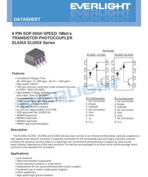
4. Mechanical & Package Information
4.1 Pin Configuration and Function
The device uses an 8-pin SOP package. There are two primary pinout configurations corresponding to different part numbers:
- For EL0500 / EL0501:
- No Connection
- Anode (LED +) Cathode (LED -)
No Connection
Ground (GND)
Output (VOUT)
7. Bias Voltage (VB) - This pin is key for speed enhancement.
8. Supply Voltage (VCC)
- For EL0452 / EL0453:
- No Connection
- Anode (LED +) Cathode (LED -)
No Connection
Ground (GND)
Output (VOUT)
7. No Connection
8. Supply Voltage (VCC)
The presence of the VB Pin (Pin 7) in the EL0500/01 allows external biasing of the photodiode, which is the mechanism for achieving higher speed. The EL0452/43 variants likely have this bias network internally configured.
5. Application Guidelines
5.1 Typical Application Circuits
The datasheet includes reference test circuits for measuring switching time and common-mode transient immunity (Figures 8 & 9). These circuits serve as a guide for implementation:
- Da'irar Gwajin Lokacin Sauyawa: Yawanci ya ƙunshi tuƙi da LED shigarwa tare da janareta bugun jini ta hanyar resistor mai iyakancewar ƙarfin lantarki. An haɗa fitarwa zuwa VCC via a pull-up resistor (R = 4.1kΩ or 1.9kΩ as specified) and monitored with an oscilloscope.L The propagation delay is measured between the 50% points of the input and output waveforms.
- Transient Immunity Test Circuit: Involves applying a high-voltage, fast-rising common-mode pulse (VCM) between the shorted input pins (1-4) and shorted output pins (5-8). The output state is monitored to ensure it does not falsely toggle due to the transient.
5.2 Design Considerations
- LED Current Limiting: An external resistor must be used in series with the input LED to set the forward current (IF). The value is calculated based on the supply voltage, the LED's forward voltage (VF), and the desired IF (often 16 mA for optimal speed/CTR).
- Output Load Resistor (RL): The choice of pull-up resistor affects switching speed, power consumption, and logic levels. A smaller RL provides faster rise times but increases power dissipation when the output is low. The datasheet specifies test conditions with RL=4.1kΩ for EL0500 and 1.9kΩ for the others.
- Noise Immunity: For applications in electrically noisy environments (motor drives, industrial controls), selecting the EL0453 variant for its high guaranteed CMTI is critical. Proper PCB layout, with short traces and decoupling capacitors close to the device pins, is also essential.
- CTR Degradation: Like all optocouplers, the CTR of these devices will gradually decrease over time, especially when operated at high temperatures and high LED currents. Design should include sufficient margin to ensure circuit functionality over the product's intended lifetime.
6. Technical Comparison & Selection Guide
The EL045X/EL050X series offers a range of options tailored for different needs:
- EL0500 vs. EL0501 / EL0452 / EL0453: The primary difference is the Current Transfer Ratio (CTR). The EL0500 has a lower minimum CTR (7% vs. 19%), making it suitable for applications where the input drive current can be higher. The others offer higher sensitivity.
- EL0453 vs. Others: The EL0453 stands out due to its guaranteed minimum Common Mode Transient Immunity of 15 kV/µs. This makes it the preferred choice for high-noise isolation applications like switching power supply feedback loops or motor drive inverter gate drives, where voltage spikes are common. The other variants specify a typical CMTI of 1000 V/µs.
- Pin Configuration: The EL0500/01 have an active VB pin (7), while the EL0452/43 have it as NC. This reflects internal architectural differences for speed optimization.
Selection Summary: Choose EL0453 for highest noise immunity. Choose EL0501/EL0452 for higher sensitivity and standard speed. Choose EL0500 for cost-sensitive applications where lower CTR is acceptable and drive current is not a constraint.
7. Packaging and Ordering Information
The devices are available in different packaging options to suit production needs.
- Standard Packaging: 100 units per tube.
- Tape and Reel Options: Available in TA or TB reel types, containing 2000 units per reel. This is suitable for automated surface-mount assembly.
- VDE Option: Parts can be ordered with VDE certification (indicated by the "-V" suffix).
- Part Numbering: The part number follows the format: EL050X(Z)-V or EL045X(Z)-V, where:
- X = Device number (0,1 for EL050x; 2,3 for EL045x).
- Z = Tape & Reel option (TA, TB, or blank for tube).
- -V = Optional VDE certification.
8. Principle of Operation
Na'urar tana aiki bisa ka'idar haɗin gani don keɓewar lantarki. Sigina na lantarki da aka yi amfani da shi a gefen shigarwa yana sa LED infrared ya fitar da haske daidai gwargwado da ƙarfin halin yanzu. Wannan hasken yana ratsa tazarar keɓewa (yawanci dielectric mai gani) kuma ya bugi mai gano hoto a gefen fitarwa. A cikin wannan jerin, mai gano shine diode mai hankali ga haske wanda aka haɗa shi da gindin transistor mai sauri. Fil din banbance (VB In some variants, allows pre-biasing the photodiode, which minimizes its junction capacitance. When light hits the photodiode, it generates a current that directly drives the base of the transistor, turning it on. This design avoids the large Miller capacitance associated with a standard phototransistor's base-collector junction, enabling much faster switching speeds—up to 1 Mbit/s. The optical path provides galvanic isolation, blocking high voltages (up to 3750 Vrms) and rejecting common-mode noise between the input and output circuits.
9. Application Scenarios
- Switch-Mode Power Supply (SMPS) Feedback Loops: Providing isolated voltage feedback from the secondary side to the primary side controller, requiring both speed for loop stability and high CMTI to withstand switching noise.
- Motor Drive Inverter Isolation: Isolating gate drive signals for IGBTs or MOSFETs in variable frequency drives. The high CMTI of the EL0453 is essential here to prevent false triggering from high dv/dt transients.
- Industrial Communication Interfaces: Acting as line receivers for isolated RS-485, CAN, or Profibus networks, protecting sensitive logic circuits from ground loops and surges.
- Telecommunication Equipment: Providing signal isolation in line cards or interface modules.
- Replacement for Low-Speed Phototransistor Couplers: Upgrading existing designs to achieve higher data rates without changing the board footprint (SO-8 compatible).
- Home Appliance Control: Isolating user interface microcontrollers from power switching sections (e.g., in washing machines, air conditioners).
10. Frequently Asked Questions (FAQ)
Q1: Menene babban bambanci tsakanin EL0500 da EL0501?
A1: Babban bambanci shine tabbataccen mafi ƙarancin Rukunin Canja wurin Halin yanzu (CTR). EL0500 yana da ƙaramin ƙaramin CTR (7% a ƙayyadadden yanayi) idan aka kwatanta da EL0501 (19%). Wannan yana nufin EL0501 ya fi kula kuma yana iya aiki tare da ƙaramin ƙaramin LED na shigarwa don cimma irin wannan fitarwa, amma EL0500 na iya zama isa kuma ya fi dacewa da tsada a cikin da'irori da aka tsara don manyan hanyoyin tuƙi.
Q2: Yaushe ne ya kamata in zaɓi musamman bambancin EL0453?
A2: You should choose the EL0453 when your application operates in an environment with very high electrical noise and fast voltage transients between the isolated grounds. Its guaranteed minimum 15 kV/µs Common Mode Transient Immunity makes it essential for reliable operation in motor drives, high-power switch-mode power supplies, or industrial control systems where other variants might experience false switching.
Q3: How do I select the value for the LED current-limiting resistor (Rseries)?
A3: Use Ohm's law: Rseries = (Vsupply - VF) / IF. VF is the LED forward voltage (use 1.8V max for design margin). IF is your desired operating current (16 mA is a common test condition for optimal performance). For a 5V supply: Rseries ≈ (5V - 1.8V) / 0.016A ≈ 200 Ω. Always check power dissipation in the resistor.
Q4: Can I use these photocouplers for analog signal isolation?
A4: E yɛ, nanso wɔde wɔn ho hyɛɛ digital (on/off) signal isolation mu pɛpɛɛpɛ efisɛ wɔn transistor output ne non-linear CTR nsusuwii. Linear analog isolation de, dedicated linear optocoupler anaa isolation amplifier bɛyɛ nhwehwɛmu a ɛfata.
Q5: EL0500/01 so VB pin no dwumadi bɛn?
A5: VB pin no wɔde de bias voltage hyɛ internal photodiode no mu. Sɛ wɔde bias photodiode no yɛ adwuma yiye a, ɛbɛtumi atumi atew ne junction capacitance a ɛyɛ speed-limiting factor kɛse no so. External bias network yi na ɛma saa dwumadie yi (1 Mbit/s) tumi yɛ adwuma a ɛyɛ den sen simple phototransistor couplers.
LED Specification Terminology
Complete explanation of LED technical terms
Photoelectric Performance
| Term | Unit/Representation | Simple Explanation | Why Important |
|---|---|---|---|
| Luminous Efficacy | lm/W (lumens per watt) | Light output per watt of electricity, higher means more energy efficient. | Directly determines energy efficiency grade and electricity cost. |
| Luminous Flux | lm (lumens) | Total light emitted by source, commonly called "brightness". | Determines if the light is bright enough. |
| Kallon Duba | ° (digiri), misali, 120° | Kuskuren da ƙarfin haske ya ragu zuwa rabi, yana ƙayyade faɗin katako. | Affects illumination range and uniformity. |
| CCT (Color Temperature) | K (Kelvin), misal, 2700K/6500K | Gumi/ƙanƙanin haske, ƙananan ƙimomi suna rawaya/dumi, mafi girma fari/sanyi. | Yana ƙayyade yanayin hasken wuta da yanayin da suka dace. |
| CRI / Ra | Unitless, 0–100 | Ability to render object colors accurately, Ra≥80 is good. | Affects color authenticity, used in high-demand places like malls, museums. |
| SDCM | MacAdam ellipse steps, e.g., "5-step" | Color consistency metric, smaller steps mean more consistent color. | Ensures uniform color across same batch of LEDs. |
| Dominant Wavelength | nm (nanometers), e.g., 620nm (red) | Wavelength corresponding to color of colored LEDs. | Determines hue of red, yellow, green monochrome LEDs. |
| Spectral Distribution | Wavelength vs intensity curve | Shows intensity distribution across wavelengths. | Affects color rendering and quality. |
Electrical Parameters
| Term | Symbol | Simple Explanation | Design Considerations |
|---|---|---|---|
| Forward Voltage | Vf | Minimum voltage to turn on LED, like "starting threshold". | Driver voltage must be ≥Vf, voltages add up for series LEDs. |
| Forward Current | If | Current value for normal LED operation. | Usually constant current drive, current determines brightness & lifespan. |
| Max Pulse Current | Ifp | Peak current tolerable for short periods, used for dimming or flashing. | Pulse width & duty cycle must be strictly controlled to avoid damage. |
| Reverse Voltage | Vr | Max reverse voltage LED can withstand, beyond may cause breakdown. | Circuit must prevent reverse connection or voltage spikes. |
| Thermal Resistance | Rth (°C/W) | Resistance to heat transfer from chip to solder, lower is better. | High thermal resistance requires stronger heat dissipation. |
| ESD Immunity | V (HBM), e.g., 1000V | Ability to withstand electrostatic discharge, higher means less vulnerable. | Anti-static measures needed in production, especially for sensitive LEDs. |
Thermal Management & Reliability
| Term | Key Metric | Simple Explanation | Impact |
|---|---|---|---|
| Junction Temperature | Tj (°C) | Gaskiyar zafin aiki a cikin guntu na LED. | Kowane raguwar 10°C na iya ninka tsawon rayuwa; yawan zafi yana haifar da raguwar haske, canjin launi. |
| Kupungua kwa Lumen | L70 / L80 (masaa) | Time for brightness to drop to 70% or 80% of initial. | Directly defines LED "service life". |
| Lumen Maintenance | % (e.g., 70%) | Percentage of brightness retained after time. | Indicates brightness retention over long-term use. |
| Color Shift | Δu′v′ or MacAdam ellipse | Degree of color change during use. | Affects color consistency in lighting scenes. |
| Thermal Aging | Material degradation | Deterioration due to long-term high temperature. | May cause brightness drop, color change, or open-circuit failure. |
Packaging & Materials
| Term | Common Types | Simple Explanation | Features & Applications |
|---|---|---|---|
| Package Type | EMC, PPA, Ceramic | Housing material protecting chip, providing optical/thermal interface. | EMC: yana da kyau mai jure zafi, ƙarancin farashi; Ceramic: mafi kyau zubar da zafi, tsawon rai. |
| Tsarin Chip | Gaba, Flip Chip | Chip electrode arrangement. | Flip chip: better heat dissipation, higher efficacy, for high-power. |
| Phosphor Coating | YAG, Silicate, Nitride | Covers blue chip, converts some to yellow/red, mixes to white. | Different phosphors affect efficacy, CCT, and CRI. |
| Lens/Optics | Flat, Microlens, TIR | Optical structure on surface controlling light distribution. | Determines viewing angle and light distribution curve. |
Quality Control & Binning
| Term | Binning Content | Simple Explanation | Purpose |
|---|---|---|---|
| Luminous Flux Bin | Code e.g., 2G, 2H | Grouped by brightness, each group has min/max lumen values. | Ensures uniform brightness in same batch. |
| Voltage Bin | Code e.g., 6W, 6X | An rarrabe ta hanyar kewayon ƙarfin lantarki na gaba. | Facilitates driver matching, improves system efficiency. |
| Color Bin | 5-step MacAdam ellipse | An rarraba ta hanyar daidaitawar launi, tabbatar da ƙuntataccen kewayon. | Yana ba da tabbacin daidaiton launi, yana guje wa rashin daidaiton launi a cikin kayan haske. |
| CCT Bin | 2700K, 3000K etc. | Grouped by CCT, each has corresponding coordinate range. | Meets different scene CCT requirements. |
Testing & Certification
| Term | Standard/Test | Simple Explanation | Significance |
|---|---|---|---|
| LM-80 | Lumen maintenance test | Long-term lighting at constant temperature, recording brightness decay. | Used to estimate LED life (with TM-21). |
| TM-21 | Standard ya kimaisha | Inakadiri maisha chini ya hali halisi kulingana na data ya LM-80. | Inatoa utabiri wa kisayansi wa maisha. |
| IESNA | Illuminating Engineering Society | Covers optical, electrical, thermal test methods. | Industry-recognized test basis. |
| RoHS / REACH | Takardun muhalli | Yana tabbatar da babu abubuwa masu cutarwa (gubar, mercury). | Market access requirement internationally. |
| ENERGY STAR / DLC | Energy efficiency certification | Energy efficiency and performance certification for lighting. | Used in government procurement, subsidy programs, enhances competitiveness. |