Teburin Abubuwan Ciki
- 1. Bayanin Samfur
- 2. Zurfin Binciken Ƙayyadaddun Fasaha
- 2.1 Matsakaicin Matsakaicin Matsayi
- 2.2 Halayen Lantarki da Na'urar Gani (Ta = 25°C)
- 3. Binciken Lanƙwasa Aiki
- 3.1 Gaba Current vs. Yanayin Yanayi
- 3.2 Rarraba Tsarin Tsarin Tsarin Tsarin Tsarin Tsarin Tsarin Tsarin Tsarin Tsarin Tsarin Tsarin Tsarin Tsarin Tsarin Tsarin Tsarin Tsarin Tsarin Tsarin Tsarin Tsarin Tsarin Tsarin Tsarin Tsarin Tsarin Tsarin Tsarin Tsarin Tsarin Tsarin Tsarin Tsarin Tsarin Tsarin Tsarin Tsarin Tsarin Tsarin Tsarin Tsarin Tsarin Tsarin Tsarin Tsarin Tsarin Tsarin Tsarin Tsarin Tsarin Tsarin Tsarin Tsarin Tsarin Tsarin Tsarin Tsarin Tsarin Tsarin Tsarin Tsarin Tsarin Tsarin Tsarin Tsarin Tsarin Tsarin Tsarin Tsarin Tsarin Tsarin Tsarin Tsarin Tsarin Tsarin Tsarin Tsarin Tsarin Tsarin Tsarin Tsarin Tsarin Tsarin Tsarin Tsarin Tsarin Tsarin Tsarin Tsarin Tsarin Tsarin Tsarin Tsarin Tsarin Tsarin Tsarin Tsarin Tsarin Tsarin Tsarin Tsarin Tsarin Tsarin Tsarin Tsarin Tsarin Tsarin Tsarin Tsarin Tsarin Tsarin Tsarin Tsarin Tsarin Tsarin Tsarin Tsarin Tsarin Tsarin Tsarin Tsarin Tsarin Tsarin Tsarin Tsarin Tsarin Tsarin Tsarin Tsarin Tsarin Tsarin Tsarin Tsarin Tsarin Tsarin Tsarin Tsarin Tsarin Tsarin Tsarin Tsarin Tsarin Tsarin Tsarin Tsarin Tsarin Tsarin Tsarin Tsarin Tsarin Tsarin Tsarin Tsarin Tsarin Tsarin Tsarin Tsarin Tsarin Tsarin Tsarin Tsarin Tsarin Tsarin Tsarin Tsarin Tsarin Tsarin Tsarin Tsarin Tsarin Tsarin Tsarin Tsarin Tsarin Tsarin Tsarin Tsarin Tsarin Tsarin Tsarin Tsarin Tsarin Tsarin Tsarin Tsarin Tsarin Tsarin Tsarin Tsarin Tsarin Tsarin Tsarin Tsarin Tsarin Tsarin Tsarin Tsarin Tsarin Tsarin Tsarin Tsarin Tsarin Tsarin Tsarin Tsarin Tsarin Tsarin Tsarin Tsarin Tsarin Tsarin Tsarin Tsarin Tsarin Tsarin Tsarin Tsarin Tsarin Tsarin Tsarin Tsarin Tsarin Tsarin Tsarin Tsarin Tsarin Tsarin Tsarin Tsarin Tsarin Tsarin Tsarin Tsarin Tsarin Tsarin Tsarin Tsarin Tsarin Tsarin Tsarin Tsarin Tsarin Tsarin Tsarin Tsarin Tsarin Tsarin Tsarin Tsarin Tsarin Tsarin Tsarin Tsarin Tsarin Tsarin Tsarin Tsarin Tsarin Tsarin Tsarin Tsarin Tsarin Tsarin Tsarin Tsarin Tsarin Tsarin Tsarin Tsarin Tsarin Tsarin Tsarin Tsarin Tsarin Tsarin Tsarin Tsarin Tsarin Tsarin Tsarin Tsarin Tsarin Tsarin Tsarin Tsarin Tsarin Tsarin Tsarin Tsarin Tsarin Tsarin Tsarin Tsarin Tsarin Tsarin Tsarin Tsarin Tsarin Tsarin Tsarin Tsarin Tsarin Tsarin Tsarin Tsarin Tsarin Tsarin Tsarin Tsarin Tsarin Tsarin Tsarin Tsarin Tsarin Tsarin Tsarin Tsarin Tsarin Tsarin Tsarin Tsarin Tsarin Tsarin Tsarin Tsarin Tsarin Tsarin Tsarin Tsarin Tsarin Tsarin Tsarin Tsarin Tsarin Tsarin Tsarin Tsarin Tsarin Tsarin Tsarin Tsarin Tsarin Tsarin Tsarin Tsarin Tsarin Tsarin Tsarin Tsarin Tsarin Tsarin Tsarin Tsarin Tsarin Tsarin Tsarin Tsarin Tsarin Tsarin Tsarin Tsarin Tsarin Tsarin Tsarin Tsarin Tsarin Tsarin Tsarin Tsarin Tsarin Tsarin Tsarin Tsarin Tsarin Tsarin Tsarin Tsarin Tsarin Tsarin Tsarin Tsarin Tsarin Tsarin Tsarin Tsarin Tsarin Tsarin Tsarin Tsarin Tsarin Tsarin Tsarin Tsarin Tsarin Tsarin Tsarin Tsarin Tsarin Tsarin Tsarin Tsarin Tsarin Tsarin Tsarin Tsarin Tsarin Tsarin Tsarin Tsarin Tsarin Tsarin Tsarin Tsarin Tsarin Tsarin Tsarin Tsarin Tsarin Tsarin Tsarin Tsarin Tsarin Tsarin Tsarin Tsarin Tsarin Tsarin Tsarin Tsarin Tsarin Tsarin Tsarin Tsarin Tsarin Tsarin Tsarin Tsarin Tsarin Tsarin Tsarin Tsarin Tsarin Tsarin Tsarin Tsarin Tsarin Tsarin Tsarin Tsarin Tsarin Tsarin Tsarin Tsarin Tsarin Tsarin Tsarin Tsarin Tsarin Tsarin Tsarin Tsarin Tsarin Tsarin Tsarin Tsarin Tsarin Tsarin Tsarin Tsarin Tsarin Tsarin Tsarin Tsarin Tsarin Tsarin Tsarin Tsarin Tsarin Tsarin Tsarin Tsarin Tsarin Tsarin Tsarin Tsarin Tsarin Tsarin Tsarin Tsarin Tsarin Tsarin Tsarin Tsarin Tsarin Tsarin Tsarin Tsarin Tsarin Tsarin Tsarin Tsarin Tsarin Tsarin Tsarin Tsarin Tsarin Tsarin Tsarin Tsarin Tsarin Tsarin Tsarin Tsarin Tsarin Tsarin Tsarin Tsarin Tsarin Tsarin Tsarin Tsarin Tsarin Tsarin Tsarin Tsarin Tsarin Tsarin Tsarin Tsarin Tsarin Tsarin Tsarin Tsarin Tsarin Tsarin Tsarin Tsarin Tsarin Tsarin Tsarin Tsarin Tsarin Tsarin Tsarin Tsarin Tsarin Tsarin Tsarin Tsarin Tsarin Tsarin Tsarin Tsarin Tsarin Tsarin Tsarin Tsarin Tsarin Tsarin Tsarin Tsarin Tsarin Tsarin Tsarin Tsarin Tsarin Tsarin Tsarin Tsarin Tsarin Tsarin Tsarin Tsarin Tsarin Tsarin Tsarin Tsarin Tsarin Tsarin Tsarin Tsarin Tsarin Tsarin Tsarin Tsarin Tsarin Tsarin Tsarin Tsarin Tsarin Tsarin Tsarin Tsarin Tsarin Tsarin Tsarin Tsarin Tsarin Tsarin Tsarin Tsarin Tsarin Tsarin Tsarin Tsarin Tsarin Tsarin Tsarin Tsarin Tsarin Tsarin Tsarin Tsarin Tsarin Tsarin Tsarin Tsarin Tsarin Tsarin Tsarin Tsarin Tsarin Tsarin Tsarin Tsarin Tsarin Tsarin Tsarin Tsarin Tsarin Tsarin Tsarin Tsarin Tsarin Tsarin Tsarin Tsarin Tsarin Tsarin Tsarin Tsarin Tsarin Tsarin Tsarin Tsarin Tsarin Tsarin Tsarin Tsarin Tsarin Tsarin Tsarin Tsarin Tsarin Tsarin Tsarin Tsarin Tsarin Tsarin Tsarin Tsarin Tsarin Tsarin Tsarin Tsarin Tsarin Tsarin Tsarin Tsarin Tsarin Tsarin Tsarin Tsarin Tsarin Tsarin Tsarin Tsarin Tsarin Tsarin Tsarin Tsarin Tsarin Tsarin Tsarin Tsarin Tsarin Tsarin Tsarin Tsarin Tsarin Tsarin Tsarin Tsarin Tsarin Tsarin Tsarin Tsarin Tsarin Tsarin Tsarin Tsarin Tsarin Tsarin Tsarin Tsarin Tsarin Tsarin Tsarin Tsarin Tsarin Tsarin Tsarin Tsarin Tsarin Tsarin Tsarin Tsarin Tsarin Tsarin Tsarin Tsarin Tsarin Tsarin Tsarin Tsarin Tsarin Tsarin Tsarin Tsarin Tsarin Tsarin Tsarin Tsarin Tsarin Tsarin Tsarin Tsarin Tsarin Tsarin Tsarin Tsarin Tsarin Tsarin Tsarin Tsarin Tsarin Tsarin Tsarin Tsarin Tsarin Tsarin Tsarin Tsarin Tsarin Tsarin Tsarin Tsarin Tsarin Tsarin Tsarin Tsarin Tsarin Tsarin Tsarin Tsarin Tsarin Tsarin Tsarin Tsarin Tsarin Tsarin Tsarin Tsarin Tsarin Tsarin Tsarin Tsarin Tsarin Tsarin Tsarin Tsarin Tsarin Tsarin Tsarin Tsarin Tsarin Tsarin Tsarin Tsarin Tsarin Tsarin Tsarin Tsarin Tsarin Tsarin Tsarin Tsarin Tsarin Tsarin Tsarin Tsarin Tsarin Tsarin Tsarin Tsarin Tsarin Tsarin Tsarin Tsarin Tsarin Tsarin Tsarin Tsarin Tsarin Tsarin Tsarin Tsarin Tsarin Tsarin Tsarin Tsarin Tsarin Tsarin Tsarin Tsarin Tsarin Tsarin Tsarin Tsarin Tsarin Tsarin Tsarin Tsarin Tsarin Tsarin Tsarin Tsarin Tsarin Tsarin Tsarin Tsarin Tsarin Tsarin Tsarin Tsarin Tsarin Tsarin Tsarin Tsarin Tsarin Tsarin Tsarin Tsarin Tsarin Tsarin Tsarin Tsarin Tsarin Tsarin Tsarin Tsarin Tsarin Tsarin Tsarin Tsarin Tsarin Tsarin Tsarin Tsarin Tsarin Tsarin Tsarin Tsarin Tsarin Tsarin Tsarin Tsarin Tsarin Tsarin Tsarin Tsarin Tsarin Tsarin Tsarin Tsarin Tsarin Tsarin Tsarin Tsarin Tsarin Tsarin Tsarin Tsarin Tsarin Tsarin Tsarin Tsarin Tsarin Tsarin Tsarin Tsarin Tsarin Tsarin Tsarin Tsarin Tsarin Tsarin Tsarin Tsarin Tsarin Tsarin Tsarin Tsarin Tsarin Tsarin Tsarin Tsarin Tsarin Tsarin Tsarin Tsarin Tsarin Tsarin Tsarin Tsarin Tsarin Tsarin Tsarin Tsarin Tsarin Tsarin Tsarin Tsarin Tsarin Tsarin Tsarin Tsarin Tsarin Tsarin Tsarin Tsarin Tsarin Tsarin Tsarin Tsarin Tsarin Tsarin Tsarin Tsarin Tsarin Tsarin Tsarin Tsarin Tsarin Tsarin Tsarin Tsarin Tsarin Tsarin Tsarin Tsarin Tsarin Tsarin Tsarin Tsarin Tsarin Tsarin Tsarin Tsarin Tsarin Tsarin Tsarin Tsarin Tsarin Tsarin Tsarin Tsarin Tsarin Tsarin Tsarin Tsarin Tsarin Tsarin Tsarin Tsarin Tsarin Tsarin Tsarin Tsarin Tsarin Tsarin Tsarin Tsarin Tsarin Tsarin Tsarin Tsarin Tsarin Tsarin Tsarin Tsarin Tsarin Tsarin Tsarin Tsarin Tsarin Tsarin Tsarin Tsarin Tsarin Tsarin Tsarin Tsarin Tsarin Tsarin Tsarin Tsarin Tsarin Tsarin Tsarin Tsarin Tsarin Tsarin Tsarin Tsarin Tsarin Tsarin Tsarin Tsarin Tsarin Tsarin Tsarin Tsarin Tsarin Tsarin Tsarin Tsarin Tsarin Tsarin Tsarin Tsarin Tsarin Tsarin Tsarin Tsarin Tsarin Tsarin Tsarin Tsarin Tsarin Tsarin Tsarin Tsarin Tsarin Tsarin Tsarin Tsarin Tsarin Tsarin Tsarin Tsarin Tsarin Tsarin Tsarin Tsarin Tsarin Tsarin Tsarin Tsarin Tsarin Tsarin Tsarin Tsarin Tsarin Tsarin Tsarin Tsarin Tsarin Tsarin Tsarin Tsarin Tsarin Tsarin Tsarin Tsarin Tsarin Tsarin Tsarin Tsarin Tsarin Tsarin Tsarin Tsarin Tsarin Tsarin Tsarin Tsarin Tsarin Tsarin Tsarin Tsarin Tsarin Tsarin Tsarin Tsarin Tsarin Tsarin Tsarin Tsarin Tsarin Tsarin Tsarin Tsarin Tsarin Tsarin Tsarin Tsarin Tsarin Tsarin Tsarin Tsarin Tsarin Tsarin Tsarin Tsarin Tsarin Tsarin Tsarin Tsarin Tsarin Tsarin Tsarin Tsarin Tsarin Tsarin Tsarin Tsarin Tsarin Tsarin Tsarin Tsarin Tsarin Tsarin Tsarin Tsarin Tsarin Tsarin Tsarin Tsarin Tsarin Tsarin Tsarin Tsarin Tsarin Tsarin Tsarin Tsarin Tsarin Tsarin Tsarin Tsarin Tsarin Tsarin Tsarin Tsarin Tsarin Tsarin Tsarin Tsarin Tsarin Tsarin Tsarin Tsarin Tsarin Tsarin Tsarin Tsarin Tsarin Tsarin Tsarin Tsarin Tsarin Tsarin Tsarin Tsarin Tsarin Tsarin Tsarin Tsarin Tsarin Tsarin Tsarin Tsarin Tsarin Tsarin Tsarin Tsarin Tsarin Tsarin Tsarin Tsarin Tsarin Tsarin Tsarin Tsarin Tsarin Tsarin Tsarin Tsarin Tsarin Tsarin Tsarin Tsarin Tsarin Tsarin Tsarin Tsarin Tsarin Tsarin Tsarin Tsarin Tsarin Tsarin Tsarin Tsarin Tsarin Tsarin Tsarin Tsarin Tsarin Tsarin Tsarin Tsarin Tsarin Tsarin Tsarin Tsarin Tsarin Tsarin Tsarin Tsarin Tsarin Tsarin Tsarin Tsarin Tsarin Tsarin Tsarin Tsarin Tsarin Tsarin Tsarin Tsarin Tsarin Tsarin Tsarin Tsarin Tsarin Tsarin Tsarin Tsarin Tsarin Tsarin Tsarin Tsarin Tsarin Tsarin Tsarin Tsarin Tsarin Tsarin Tsarin Tsarin Tsarin Tsarin Tsarin Tsarin Tsarin Tsarin Tsarin Tsarin Tsarin Tsarin Tsarin Tsarin Tsarin Tsarin Tsarin Tsarin Tsarin Tsarin Tsarin Tsarin Tsarin Tsarin Tsarin Tsarin Tsarin Tsarin Tsarin Tsarin Tsarin Tsarin Tsarin Tsarin Tsarin Tsarin Tsarin Tsarin Tsarin Tsarin Tsarin Tsarin Tsarin Tsarin Tsarin Tsarin Tsarin Tsarin Tsarin Tsarin Tsarin Tsarin Tsarin Tsarin Tsarin Tsarin Tsarin Tsarin Tsarin Tsarin Tsarin Tsarin Tsarin Tsarin Tsarin Tsarin Tsarin Tsarin Tsarin Tsarin Tsarin Tsarin Tsarin Tsarin Tsarin Tsarin Tsarin Tsarin Tsarin Tsarin Tsarin Tsarin Tsarin Tsarin Tsarin Tsarin Tsarin Tsarin Tsarin Tsarin Tsarin Tsarin Tsarin Tsarin Tsarin Tsarin Tsarin Tsarin Tsarin Tsarin Tsarin Tsarin Tsarin Tsarin Tsarin Tsarin Tsarin Tsarin Tsarin Tsarin Tsarin Tsarin Tsarin Tsarin Tsarin Tsarin Tsarin Tsarin Tsarin Tsarin Tsarin Tsarin Tsarin Tsarin Tsarin Tsarin Tsarin Tsarin Tsarin Tsarin Tsarin Tsarin Tsarin Tsarin Tsarin Tsarin Tsarin Tsarin Tsarin Tsarin Tsarin Tsarin Tsarin Tsarin Tsarin Tsarin Tsarin Tsarin Tsarin Tsarin Tsarin Tsarin Tsarin Tsarin Tsarin Tsarin Tsarin Tsarin Tsarin Tsarin Tsarin Tsarin Tsarin Tsarin Tsarin Tsarin Tsarin Tsarin Tsarin Tsarin Tsarin Tsarin Tsarin Tsarin Tsarin Tsarin Tsarin Tsarin Tsarin Tsarin Tsarin Tsarin Tsarin Tsarin Tsarin Tsarin Tsarin Tsarin Tsarin Tsarin Tsarin Tsarin Tsarin Tsarin Tsarin Tsarin Tsarin Tsarin Tsarin Tsarin Tsarin Tsarin Tsarin Tsarin Tsarin Tsarin Tsarin Tsarin Tsarin Tsarin Tsarin Tsarin Tsarin Tsarin Tsarin Tsarin Tsarin Tsarin Tsarin Tsarin Tsarin Tsarin Tsarin Tsarin Tsarin Tsarin Tsarin Tsarin Tsarin Tsarin Tsarin Tsarin Tsarin Tsarin Tsarin Tsarin Tsarin Tsarin Tsarin Tsarin Tsarin Tsarin Tsarin Tsarin Tsarin Tsarin Tsarin Tsarin Tsarin Tsarin Tsarin Tsarin Tsarin Tsarin Tsarin Tsarin Tsarin Tsarin Tsarin Tsarin Tsarin Tsarin Tsarin Tsarin Tsarin Tsarin Tsarin Tsarin Tsarin Tsarin Tsarin Tsarin Tsarin Tsarin Tsarin Tsarin Tsarin Tsarin Tsarin Tsarin Tsarin Tsarin Tsarin Tsarin Tsarin Tsarin Tsarin Tsarin Tsarin Tsarin Tsarin Tsarin Tsarin Tsarin Tsarin Tsarin Tsarin Tsarin Tsarin Tsarin Tsarin Tsarin Tsarin Tsarin Tsarin Tsarin Tsarin Tsarin Tsarin Tsarin Tsarin Tsarin Tsarin Tsarin Tsarin Tsarin Tsarin Tsarin Tsarin Tsarin Tsarin Tsarin Tsarin Tsarin Tsarin Tsarin Tsarin Tsarin Tsarin Tsarin Tsarin Tsarin Tsarin Tsarin Tsarin Tsarin Tsarin Tsarin Tsarin Tsarin Tsarin Tsarin Tsarin Tsarin Tsarin Tsarin Tsarin Tsarin Tsarin Tsarin Tsarin Tsarin Tsarin Tsarin Tsarin Tsarin Tsarin Tsarin Tsarin Tsarin Tsarin Tsarin Tsarin Tsarin Tsarin Tsarin Tsarin Tsarin Tsarin Tsarin Tsarin Tsarin Tsarin Tsarin Tsarin Tsarin Tsarin Tsarin Tsarin Tsarin Tsarin Tsarin Tsarin Tsarin Tsarin Tsarin Tsarin Tsarin Tsarin Tsarin Tsarin Tsarin Tsarin Tsarin Tsarin Tsarin Tsarin Tsarin Tsarin Tsarin Tsarin Tsarin Tsarin Tsarin Tsarin Tsarin Tsarin Tsarin Tsarin Tsarin Tsarin Tsarin Tsarin Tsarin Tsarin Tsarin Tsarin Tsarin Tsarin Tsarin Tsarin Tsarin Tsarin Tsarin Tsarin Tsarin Tsarin Tsarin Tsarin Tsarin Tsarin Tsarin Tsarin Tsarin Tsarin Tsarin Tsarin Tsarin Tsarin Tsarin Tsarin Tsarin Tsarin Tsarin Tsarin Tsarin Tsarin Tsarin Tsarin Tsarin Tsarin Tsarin Tsarin Tsarin Tsarin Tsarin Tsarin Tsarin Tsarin Tsarin Tsarin Tsarin Tsarin Tsarin Tsarin Tsarin Tsarin Tsarin Tsarin Tsarin Tsarin Tsarin Tsarin Tsarin Tsarin Tsarin Tsarin Tsarin Tsarin Tsarin Tsarin Tsarin Tsarin Tsarin Tsarin Tsarin Tsarin Tsarin Tsarin Tsarin Tsarin Tsarin Tsarin Tsarin Tsarin Tsarin Tsarin Tsarin Tsarin Tsarin Tsarin Tsarin Tsarin Tsarin Tsarin Tsarin Tsarin Tsarin Tsarin Tsarin Tsarin Tsarin Tsarin Tsarin Tsarin Tsarin Tsarin Tsarin Tsarin Tsarin Tsarin Tsarin Tsarin Tsarin Tsarin Tsarin Tsarin Tsarin Tsarin Tsarin Tsarin Tsarin Tsarin Tsarin Tsarin Tsarin Tsarin Tsarin Tsarin Tsarin Tsarin Tsarin Tsarin Tsarin Tsarin Tsarin Tsarin Tsarin Tsarin Tsarin Tsarin Tsarin Tsarin Tsarin Tsarin Tsarin Tsarin Tsarin Tsarin Tsarin Tsarin Tsarin Tsarin Tsarin Tsarin Tsarin Tsarin Tsarin Tsarin Tsarin Tsarin Tsarin Tsarin Tsarin Tsarin Tsarin Tsarin Tsarin Tsarin Tsarin Tsarin Tsarin Tsarin Tsarin Tsarin Tsarin Tsarin Tsarin Tsarin Tsarin Tsarin Tsarin Tsarin Tsarin Tsarin Tsarin Tsarin Tsarin Tsarin Tsarin Tsarin Tsarin Tsarin Tsarin Tsarin Tsarin Tsarin Tsarin Tsarin Tsarin Tsarin Tsarin Tsarin Tsarin Tsarin Tsarin Tsarin Tsarin Tsarin Tsarin Tsarin Tsarin Tsarin Tsarin Tsarin Tsarin Tsarin Tsarin Tsarin Tsarin Tsarin Tsarin Tsarin Tsarin Tsarin Tsarin Tsarin Tsarin Tsarin Tsarin Tsarin Tsarin Tsarin Tsarin Tsarin Tsarin Tsarin Tsarin Tsarin Tsarin Tsarin Tsarin Tsarin Tsarin Tsarin Tsarin Tsarin Tsarin Tsarin Tsarin Tsarin Tsarin Tsarin Tsarin Tsarin Tsarin Tsarin Tsarin Tsarin Tsarin Tsarin Tsarin Tsarin Tsarin Tsarin Tsarin Tsarin Tsarin Tsarin Tsarin Tsarin Tsarin Tsarin Tsarin Tsarin Tsarin Tsarin Tsarin Tsarin Tsarin Tsarin Tsarin Tsarin Tsarin Tsarin Tsarin Tsarin Tsarin Tsarin Tsarin Tsarin Tsarin Tsarin Tsarin Tsarin Tsarin Tsarin Tsarin Tsarin Tsarin Tsarin Tsarin Tsarin Tsarin Tsarin Tsarin Tsarin Tsarin Tsarin Tsarin Tsarin Tsarin Tsarin Tsarin Tsarin Tsarin Tsarin Tsarin Tsarin Tsarin Tsarin Tsarin Tsarin Tsarin Tsarin Tsarin Tsarin Tsarin Tsarin Tsarin Tsarin Tsarin Tsarin Tsarin Tsarin Tsarin Tsarin Tsarin Tsarin Tsarin Tsarin Tsarin Tsarin Tsarin Tsarin Tsarin Tsarin Tsarin Tsarin Tsarin Tsarin Tsarin Tsarin Tsarin Tsarin Tsarin Tsarin Tsarin Tsarin Tsarin Tsarin Tsarin Tsarin Tsarin Tsarin Tsarin Tsarin Tsarin Tsarin Tsarin Tsarin Tsarin Tsarin Tsarin Tsarin Tsarin Tsarin Tsarin Tsarin Tsarin Tsarin Tsarin Tsarin Tsarin Tsarin Tsarin Tsarin Tsarin Tsarin Tsarin Tsarin Tsarin Tsarin Tsarin Tsarin Tsarin Tsarin Tsarin Tsarin Tsarin Tsarin Tsarin Tsarin Tsarin Tsarin Tsarin Tsarin Tsarin Tsarin Tsarin Tsarin Tsarin Tsarin Tsarin Tsarin Tsarin Tsarin Tsarin Tsarin Tsarin Tsarin Tsarin Tsarin Tsarin Tsarin Tsarin Tsarin Tsarin Tsarin Tsarin Tsarin Tsarin Tsarin Tsarin Tsarin Tsarin Tsarin Tsarin Tsarin Tsarin Tsarin Tsarin Tsarin Tsarin Tsarin Tsarin Tsarin Tsarin Tsarin Tsarin Tsarin Tsarin Tsarin Tsarin Tsarin Tsarin Tsarin Tsarin Tsarin Tsarin Tsarin Tsarin Tsarin Tsarin Tsarin Tsarin Tsarin Tsarin Tsarin Tsarin Tsarin Tsarin Tsarin Tsarin Tsarin Tsarin Tsarin Tsarin Tsarin Tsarin Tsarin Tsarin Tsarin Tsarin Tsarin Tsarin Tsarin Tsarin Tsarin Tsarin Tsarin Tsarin Tsarin Tsarin Tsarin Tsarin Tsarin Tsarin Tsarin Tsarin Tsarin Tsarin Tsarin Tsarin Tsarin Tsarin Tsarin Tsarin Tsarin Tsarin Tsarin Tsarin Tsarin Tsarin Tsarin Tsarin Tsarin Tsarin Tsarin Tsarin Tsarin Tsarin Tsarin Tsarin Tsarin Tsarin Tsarin Tsarin Tsarin Tsarin Tsarin Tsarin Tsarin Tsarin Tsarin Tsarin Tsarin Tsarin Tsarin Tsarin Tsarin Tsarin Tsarin Tsarin Tsarin Tsarin Tsarin Tsarin Tsarin Tsarin Tsarin Tsarin Tsarin Tsarin Tsarin Tsarin Tsarin Tsarin Tsarin Tsarin Tsarin Tsarin Tsarin Tsarin Tsarin Tsarin Tsarin Tsarin Tsarin Tsarin Tsarin Tsarin Tsarin Tsarin Tsarin Tsarin Tsarin Tsarin Tsarin Tsarin Tsarin Tsarin Tsarin Tsarin Tsarin Tsarin Tsarin Tsarin Tsarin Tsarin Tsarin Tsarin Tsarin Tsarin Tsarin Tsarin Tsarin Tsarin Tsarin Tsarin Tsarin Tsarin Tsarin Tsarin Tsarin Tsarin Tsarin Tsarin Tsarin Tsarin Tsarin Tsarin Tsarin Tsarin Tsarin Tsarin Tsarin Tsarin Tsarin Tsarin Tsarin Tsarin Tsarin Tsarin Tsarin Tsarin Tsarin Tsarin Tsarin Tsarin Tsarin Tsarin Tsarin Tsarin Tsarin Tsarin Tsarin Tsarin Tsarin Tsarin Tsarin Tsarin Tsarin Tsarin Tsarin Tsarin Tsarin Tsarin Tsarin Tsarin Tsarin Tsarin Tsarin Tsarin Tsarin Tsarin Tsarin Tsarin Tsarin Tsarin Tsarin Tsarin Tsarin Tsarin Tsarin Tsarin Tsarin Tsarin Tsarin Tsarin Tsarin Tsarin Tsarin Tsarin Tsarin Tsarin Tsarin Tsarin Tsarin Tsarin Tsarin Tsarin Tsarin Tsarin Tsarin Tsarin Tsarin Tsarin Tsarin Tsarin Tsarin Tsarin Tsarin Tsarin Tsarin Tsarin Tsarin Tsarin Tsarin Tsarin Tsarin Tsarin Tsarin Tsarin Tsarin Tsarin Tsarin Tsarin Tsarin Tsarin Tsarin Tsarin Tsarin Tsarin Tsarin Tsarin Tsarin Tsarin Tsarin Tsarin Tsarin Tsarin Tsarin Tsarin Tsarin Tsarin Tsarin Tsarin Tsarin Tsarin Tsarin Tsarin Tsarin Tsarin Tsarin Tsarin Tsarin Tsarin Tsarin Tsarin Tsarin Tsarin Tsarin Tsarin Tsarin Tsarin Tsarin Tsarin Tsarin Tsarin Tsarin Tsarin Tsarin Tsarin Tsarin Tsarin Tsarin Tsarin Tsarin Tsarin Tsarin Tsarin Tsarin Tsarin Tsarin Tsarin Tsarin Tsarin Tsarin Tsarin Tsarin Tsarin Tsarin Tsarin Tsarin Tsarin Tsarin Tsarin Tsarin Tsarin Tsarin Tsarin Tsarin Tsarin Tsarin Tsarin Tsarin Tsarin Tsarin Tsarin Tsarin Tsarin Tsarin Tsarin Tsarin Tsarin Tsarin Tsarin Tsarin Tsarin Tsarin Tsarin Tsarin Tsarin Tsarin Tsarin Tsarin Tsarin Tsarin Tsarin Tsarin Tsarin Tsarin Tsarin Tsarin Tsarin Tsarin Tsarin Tsarin Tsarin Tsarin Tsarin Tsarin Tsarin Tsarin Tsarin Tsarin Tsarin Tsarin Tsarin Tsarin Tsarin Tsarin Tsarin Tsarin Tsarin Tsarin Tsarin Tsarin Tsarin Tsarin Tsarin Tsarin Tsarin Tsarin Tsarin Tsarin Tsarin Tsarin Tsarin Tsarin Tsarin Tsarin Tsarin Tsarin Tsarin Tsarin Tsarin Tsarin Tsarin Tsarin Tsarin Tsarin Tsarin Tsarin Tsarin Tsarin Tsarin Tsarin Tsarin Tsarin Tsarin Tsarin Tsarin Tsarin Tsarin Tsarin Tsarin Tsarin Tsarin Tsarin Tsarin Tsarin Tsarin Tsarin Tsarin Tsarin Tsarin Tsarin Tsarin Tsarin Tsarin Tsarin Tsarin Tsarin Tsarin Tsarin Tsarin Tsarin Tsarin Tsarin Tsarin Tsarin Tsarin Tsarin Tsarin Tsarin Tsarin Tsarin Tsarin Tsarin Tsarin Tsarin Tsarin Tsarin Tsarin Tsarin Tsarin Tsarin Tsarin Tsarin Tsarin Tsarin Tsarin Tsarin Tsarin Tsarin Tsarin Tsarin Tsarin Tsarin Tsarin Tsarin Tsarin Tsarin Tsarin Tsarin Tsarin Tsarin Tsarin Tsarin Tsarin Tsarin Tsarin Tsarin Tsarin Tsarin Tsarin Tsarin Tsarin Tsarin Tsarin Tsarin Tsarin Tsarin Tsarin Tsarin Tsarin Tsarin Tsarin Tsarin Tsarin Tsarin Tsarin Tsarin Tsarin Tsarin Tsarin Tsarin Tsarin Tsarin Tsarin Tsarin Tsarin Tsarin Tsarin Tsarin Tsarin Tsarin Tsarin Tsarin Tsarin Tsarin Tsarin Tsarin Tsarin Tsarin Tsarin Tsarin Tsarin Tsarin Tsarin Tsarin Tsarin Tsarin Tsarin Tsarin Tsarin Tsarin Tsarin Tsarin Tsarin Tsarin Tsarin Tsarin Tsarin Tsarin Tsarin Tsarin Tsarin Tsarin Tsarin Tsarin Tsarin Tsarin Tsarin Tsarin Tsarin Tsarin Tsarin Tsarin Tsarin Tsarin Tsarin Tsarin Tsarin Tsarin Tsarin Tsarin Tsarin Tsarin Tsarin Tsarin Tsarin Tsarin Tsarin Tsarin Tsarin Tsarin Tsarin Tsarin Tsarin Tsarin Tsarin Tsarin Tsarin Tsarin Tsarin Tsarin Tsarin Tsarin Tsarin Tsarin Tsarin Tsarin Tsarin Tsarin Tsarin Tsarin Tsarin Tsarin Tsarin Tsarin Tsarin Tsarin Tsarin Tsarin Tsarin Tsarin Tsarin Tsarin Tsarin Tsarin Tsarin Tsarin Tsarin Tsarin Tsarin Tsarin Tsarin Tsarin Tsarin Tsarin Tsarin Tsarin Tsarin Tsarin Tsarin Tsarin Tsarin Tsarin Tsarin Tsarin Tsarin Tsarin Tsarin Tsarin Tsarin Tsarin Tsarin Tsarin Tsarin Tsarin Tsarin Tsarin Tsarin Tsarin Tsarin Tsarin Tsarin Tsarin Tsarin Tsarin Tsarin Tsarin Tsarin Tsarin Tsarin Tsarin Tsarin Tsarin Tsarin Tsarin Tsarin Tsarin Tsarin Tsarin Tsarin Tsarin Tsarin Tsarin Tsarin Tsarin Tsarin Tsarin Tsarin Tsarin Tsarin Tsarin Tsarin Tsarin Tsarin Tsarin Tsarin Tsarin Tsarin Tsarin Tsarin Tsarin Tsarin Tsarin Tsarin Tsarin Tsarin Tsarin Tsarin Tsarin Tsarin Tsarin Tsarin Tsarin Tsarin Tsarin Tsarin Tsarin Tsarin Tsarin Tsarin Tsarin Tsarin Tsarin Tsarin Tsarin Tsarin Tsarin Tsarin Tsarin Tsarin Tsarin Tsarin Tsarin Tsarin Tsarin Tsarin Tsarin Tsarin Tsarin Tsarin Tsarin Tsarin Tsarin Tsarin Tsarin Tsarin Tsarin Tsarin Tsarin Tsarin Tsarin Tsarin Tsarin Tsarin Tsarin Tsarin Tsarin Tsarin Tsarin Tsarin Tsarin Tsarin Tsarin Tsarin Tsarin Tsarin Tsarin Tsarin Tsarin Tsarin Tsarin Tsarin Tsarin Tsarin Tsarin Tsarin Tsarin Tsarin Tsarin Tsarin Tsarin Tsarin Tsarin Tsarin Tsarin Tsarin Tsarin Tsarin Tsarin Tsarin Tsarin Tsarin Tsarin Tsarin Tsarin Tsarin Tsarin Tsarin Tsarin Tsarin Tsarin Tsarin Tsarin Tsarin Tsarin Tsarin Tsarin Tsarin Tsarin Tsarin Tsarin Tsarin Tsarin Tsarin Tsarin Tsarin Tsarin Tsarin Tsarin Tsarin Tsarin Tsarin Tsarin Tsarin Tsarin Tsarin Tsarin Tsarin Tsarin Tsarin Tsarin Tsarin Tsarin Tsarin Tsarin Tsarin Tsarin Tsarin Tsarin Tsarin Tsarin Tsarin Tsarin Tsarin Tsarin Tsarin Tsarin Tsarin Tsarin Tsarin Tsarin Tsarin Tsarin Tsarin Tsarin Tsarin Tsarin Tsarin Tsarin Tsarin Tsarin Tsarin Tsarin Tsarin Tsarin Tsarin Tsarin Tsarin Tsarin Tsarin Tsarin Tsarin Tsarin Tsarin Tsarin Tsarin Tsarin Tsarin Tsarin Tsarin Tsarin Tsarin Tsarin Tsarin Tsarin Tsarin Tsarin Tsarin Tsarin Tsarin Tsarin Tsarin Tsarin Tsarin Tsarin Tsarin Tsarin Tsarin Tsarin Tsarin Tsarin Tsarin Tsarin Tsarin Tsarin Tsarin Tsarin Tsarin Tsarin Tsarin Tsarin Tsarin Tsarin Tsarin Tsarin Tsarin Tsarin Tsarin Tsarin Tsarin Tsarin Tsarin Tsarin Tsarin Tsarin Tsarin Tsarin Tsarin Tsarin Tsarin Tsarin Tsarin Tsarin Tsarin Tsarin Tsarin Tsarin Tsarin Tsarin Tsarin Tsarin Tsarin Tsarin Tsarin Tsarin Tsarin Tsarin Tsarin Tsarin Tsarin Tsarin Tsarin Tsarin Tsarin Tsarin Tsarin Tsarin Tsarin Tsarin Tsarin Tsarin Tsarin Tsarin Tsarin Tsarin Tsarin Tsarin Tsarin Tsarin Tsarin Tsarin Tsarin Tsarin Tsarin Tsarin Tsarin Tsarin Tsarin Tsarin Tsarin Tsarin Tsarin Tsarin Tsarin Tsarin Tsarin Tsarin Tsarin Tsarin Tsarin Tsarin Tsarin Tsarin Tsarin Tsarin Tsarin Tsarin Tsarin Tsarin Tsarin Tsarin Tsarin Tsarin Tsarin Tsarin Tsarin Tsarin Tsarin Tsarin Tsarin Tsarin Tsarin Tsarin Tsarin Tsarin Tsarin Tsarin Tsarin Tsarin Tsarin Tsarin Tsarin Tsarin Tsarin Tsarin Tsarin Tsarin Tsarin Tsarin Tsarin Tsarin Tsarin Tsarin Tsarin Tsarin Tsarin Tsarin Tsarin Tsarin Tsarin Tsarin Tsarin Tsarin Tsarin Tsarin Tsarin Tsarin Tsarin Tsarin Tsarin Tsarin Tsarin Tsarin Tsarin Tsarin Tsarin Tsarin Tsarin Tsarin Tsarin Tsarin Tsarin Tsarin Tsarin Tsarin Tsarin Tsarin Tsarin Tsarin Tsarin Tsarin Tsarin Tsarin Tsarin Tsarin Tsarin Tsarin Tsarin Tsarin Tsarin Tsarin Tsarin Tsarin Tsarin Tsarin Tsarin Tsarin Tsarin Tsarin Tsarin Tsarin Tsarin Tsarin Tsarin Tsarin Tsarin Tsarin Tsarin Tsarin Tsarin Tsarin Tsarin Tsarin Tsarin Tsarin Tsarin Tsarin Tsarin Tsarin Tsarin Tsarin Tsarin Tsarin Tsarin Tsarin Tsarin Tsarin Tsarin Tsarin Tsarin Tsarin Tsarin Tsarin Tsarin Tsarin Tsarin Tsarin Tsarin Tsarin Tsarin Tsarin Tsarin Tsarin Tsarin Tsarin Tsarin Tsarin Tsarin Tsarin Tsarin Tsarin Tsarin Tsarin Tsarin Tsarin Tsarin Tsarin Tsarin Tsarin Tsarin Tsarin Tsarin Tsarin Tsarin Tsarin Tsarin Tsarin Tsarin Tsarin Tsarin Tsarin Tsarin Tsarin Tsarin Tsarin Tsarin Tsarin Tsarin Tsarin Tsarin Tsarin Tsarin Tsarin Tsarin Tsarin Tsarin Tsarin Tsarin Tsarin Tsarin Tsarin Tsarin Tsarin Tsarin Tsarin Tsarin Tsarin Tsarin Tsarin Tsarin Tsarin Tsarin Tsarin Tsarin Tsarin Tsarin Tsarin Tsarin Tsarin Tsarin Tsarin Tsarin Tsarin Tsarin Tsarin Tsarin Tsarin Tsarin Tsarin Tsarin Tsarin Tsarin Tsarin Tsarin Tsarin Tsarin Tsarin Tsarin Tsarin Tsarin Tsarin Tsarin Tsarin Tsarin Tsarin Tsarin Tsarin Tsarin Tsarin Tsarin Tsarin Tsarin Tsarin Tsarin Tsarin Tsarin Tsarin Tsarin Tsarin Tsarin Tsarin Tsarin Tsarin Tsarin Tsarin Tsarin Tsarin Tsarin Tsarin Tsarin Tsarin Tsarin Tsarin Tsarin Tsarin Tsarin Tsarin Tsarin Tsarin Tsarin Tsarin Tsarin Tsarin Tsarin Tsarin Tsarin Tsarin Tsarin Tsarin Tsarin Tsarin Tsarin Tsarin Tsarin Tsarin Tsarin Tsarin Tsarin Tsarin Tsarin Tsarin Tsarin Tsarin Tsarin Tsarin Tsarin Tsarin Tsarin Tsarin Tsarin Tsarin Tsarin Tsarin Tsarin Tsarin Tsarin Tsarin Tsarin Tsarin Tsarin Tsarin Tsarin Tsarin Tsarin Tsarin Tsarin Tsarin Tsarin Tsarin Tsarin Tsarin Tsarin Tsarin Tsarin Tsarin Tsarin Tsarin Tsarin Tsarin Tsarin Tsarin Tsarin Tsarin Tsarin Tsarin Tsarin Tsarin Tsarin Tsarin Tsarin Tsarin Tsarin Tsarin Tsarin Tsarin Tsarin Tsarin Tsarin Tsarin Tsarin Tsarin Tsarin Tsarin Tsarin Tsarin Tsarin Tsarin Tsarin Tsarin Tsarin Tsarin Tsarin Tsarin Tsarin Tsarin Tsarin Tsarin Tsarin Tsarin Tsarin Tsarin Tsarin Tsarin Tsarin Tsarin Tsarin Tsarin Tsarin Tsarin Tsarin Tsarin Tsarin Tsarin Tsarin Tsarin Tsarin Tsarin Tsarin Tsarin Tsarin Tsarin Tsarin Tsarin Tsarin Tsarin Tsarin Tsarin Tsarin Tsarin Tsarin Tsarin Tsarin Tsarin Tsarin Tsarin Tsarin Tsarin Tsarin Tsarin Tsarin Tsarin Tsarin Tsarin Tsarin Tsarin Tsarin Tsarin Tsarin Tsarin Tsarin Tsarin Tsarin Tsarin Tsarin Tsarin Tsarin Tsarin Tsarin Tsarin Tsarin Tsarin Tsarin Tsarin Tsarin Tsarin Tsarin Tsarin Tsarin Tsarin Tsarin Tsarin Tsarin Tsarin Tsarin Tsarin Tsarin Tsarin Tsarin Tsarin Tsarin Tsarin Tsarin Tsarin Tsarin Tsarin Tsarin Tsarin Tsarin Tsarin Tsarin Tsarin Tsarin Tsarin Tsarin Tsarin Tsarin Tsarin Tsarin Tsarin Tsarin Tsarin Tsarin Tsarin Tsarin Tsarin Tsarin Tsarin Tsarin Tsarin Tsarin Tsarin Tsarin Tsarin Tsarin Tsarin Tsarin Tsarin Tsarin Tsarin Tsarin Tsarin Tsarin Tsarin Tsarin Tsarin Tsarin Tsarin Tsarin Tsarin Tsarin Tsarin Tsarin Tsarin Tsarin Tsarin Tsarin Tsarin Tsarin Tsarin Tsarin Tsarin Tsarin Tsarin Tsarin Tsarin Tsarin Tsarin Tsarin Tsarin Tsarin Tsarin Tsarin Tsarin Tsarin Tsarin Tsarin Tsarin Tsarin Tsarin Tsarin Tsarin Tsarin Tsarin Tsarin Tsarin Tsarin Tsarin Tsarin Tsarin Tsarin Tsarin Tsarin Tsarin Tsarin Tsarin Tsarin Tsarin Tsarin Tsarin Tsarin Tsarin Tsarin Tsarin Tsarin Tsarin Tsarin Tsarin Tsarin Tsarin Tsarin Tsarin Tsarin Tsarin Tsarin Tsarin Tsarin Tsarin Tsarin Tsarin Tsarin Tsarin Tsarin Tsarin Tsarin Tsarin Tsarin Tsarin Tsarin Tsarin Tsarin Tsarin Tsarin Tsarin Tsarin Tsarin Tsarin Tsarin Tsarin Tsarin Tsarin Tsarin Tsarin Tsarin Tsarin Tsarin Tsarin Tsarin Tsarin Tsarin Tsarin Tsarin Tsarin Tsarin Tsarin Tsarin Tsarin Tsarin Tsarin Tsarin Tsarin Tsarin Tsarin Tsarin Tsarin Tsarin Tsarin Tsarin Tsarin Tsarin Tsarin Tsarin Tsarin Tsarin Tsarin Tsarin Tsarin Tsarin Tsarin Tsarin Tsarin Tsarin Tsarin Tsarin Tsarin Tsarin Tsarin Tsarin Tsarin Tsarin Tsarin Tsarin Tsarin Tsarin Tsarin Tsarin Tsarin Tsarin Tsarin Tsarin Tsarin Tsarin Tsarin Tsarin Tsarin Tsarin Tsarin Tsarin Tsarin Tsarin Tsarin Tsarin Tsarin Tsarin Tsarin Tsarin Tsarin Tsarin Tsarin Tsarin Tsarin Tsarin Tsarin Tsarin Tsarin Tsarin Tsarin Tsarin Tsarin Tsarin Tsarin Tsarin Tsarin Tsarin Tsarin Tsarin Tsarin Tsarin Tsarin Tsarin Tsarin Tsarin Ts
- .3 Peak Emission Wavelength vs. Temperature
- .4 Forward Current vs. Forward Voltage
- .5 Radiant Intensity vs. Angular Displacement
- .6 Relative Radiant Intensity vs. Forward Current
- . Mechanical and Packaging Information
- .1 Package Dimensions
- .2 Polarity Identification
- . Soldering and Assembly Guidelines
- .1 Storage and Moisture Sensitivity
- .2 Reflow Soldering Profile
- .3 Hand Soldering and Rework
- .4 Circuit Board Design
- . Packaging and Ordering Information
- .1 Reel and Tape Specifications
- . Application Suggestions
- .1 Typical Application Scenarios
- .2 Design Considerations
- . Reliability Testing
- . Frequently Asked Questions (FAQ)
- .1 Why is a series resistor necessary?
- .2 How do I calculate the series resistor value?
- .3 Can this LED be used for data transmission?
- .4 What is the difference between radiant intensity and power?
- . Operational Principle
- . Industry Context and Trends
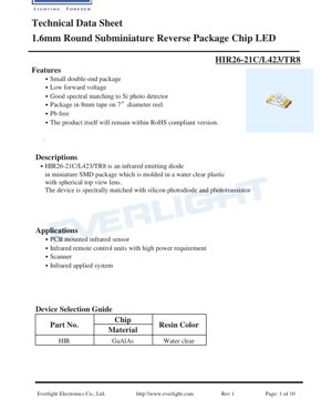
. Product Overview
The HIR26-21C/L423/TR8 is a high-performance infrared (IR) emitting diode designed for surface-mount technology (SMT) applications. This device belongs to the category of subminiature reverse package chip LEDs, featuring a compact 1.6mm round form factor. Its core function is to emit infrared light at a peak wavelength of 850 nanometers, which is optimally matched to the spectral sensitivity of silicon photodetectors and phototransistors. This makes it an ideal source for a wide range of sensing and signaling applications where invisible light transmission is required.
The LED is constructed using Gallium Aluminum Arsenide (GaAlAs) material, encapsulated in a water-clear plastic resin with a spherical lens. This design ensures efficient light extraction and a consistent radiation pattern. A key advantage of this component is its low forward voltage, which contributes to energy-efficient operation. Furthermore, the product is compliant with Pb-free and RoHS environmental standards, aligning with modern manufacturing requirements for reduced hazardous substances.
. Technical Specifications Deep Dive
.1 Absolute Maximum Ratings
These ratings define the limits beyond which permanent damage to the device may occur. Operation under these conditions is not guaranteed.
- Continuous Forward Current (IF): 65 mA
- Reverse Voltage (VR): 5 V
- Power Dissipation (Pd) at Ta≤ 25°C: 110 mW
- Operating Temperature (Topr): -40°C to +85°C
- Storage Temperature (Tstg): -40°C to +85°C
- Soldering Temperature (Tsol): 260°C (for a maximum of 10 seconds during reflow)
.2 Electro-Optical Characteristics (Ta= 25°C)
These parameters define the device's performance under typical operating conditions, measured at a forward current of 20mA unless otherwise specified.
- Radiant Intensity (Ie): 14.0 mW/sr (Min), 16.0 mW/sr (Typ). This measures the optical power emitted per unit solid angle, indicating the brightness of the IR beam.
- Peak Wavelength (λp): 850 nm (Typ). The wavelength at which the optical output power is maximum, perfectly suited for silicon-based receivers.
- Spectral Bandwidth (Δλ): 42 nm (Typ). The range of wavelengths emitted, centered around the peak wavelength.
- Forward Voltage (VF): 1.45 V (Typ), 1.70 V (Max). The voltage drop across the LED when operating at the specified current. The low typical value is a significant efficiency advantage.
- Reverse Current (IR): 10 μA (Max) at VR=5V. The small leakage current when the device is reverse-biased.
- Optical Rise/Fall Time (tr/tf): 25/15 ns (Typ), 35/35 ns (Max) at IF=50mA. These fast switching times enable high-speed pulsed operation for data transmission.
- Viewing Angle (2θ/2): 20 degrees (Typ). The full angle at which the radiant intensity is half of the maximum intensity (on-axis). This defines the beam width.
. Performance Curve Analysis
The datasheet provides several characteristic curves that are crucial for design engineers.
.1 Forward Current vs. Ambient Temperature
This curve shows the derating of the maximum allowable forward current as the ambient temperature increases. To prevent thermal damage, the forward current must be reduced when operating above 25°C. The power dissipation limit of 110mW governs this relationship.
.2 Spectral Distribution
The graph illustrates the relative radiant intensity as a function of wavelength, confirming the peak at 850nm and the approximately 42nm bandwidth. This is critical for ensuring compatibility with the receiver's spectral response.
.3 Peak Emission Wavelength vs. Temperature
The peak wavelength has a slight temperature coefficient, typically shifting by about 0.1 to 0.3 nm/°C. This curve allows designers to predict the operational wavelength shift over the intended temperature range of their application.
.4 Forward Current vs. Forward Voltage
This IV characteristic curve is essential for designing the current-limiting circuitry. It shows the non-linear relationship between current and voltage, highlighting the importance of using a series resistor or constant current driver to set the operating point.
.5 Radiant Intensity vs. Angular Displacement
This polar plot visually defines the 20-degree viewing angle. The radiation pattern is approximately Lambertian within this cone, which is important for calculating the irradiance on a target at a given distance and angle.
.6 Relative Radiant Intensity vs. Forward Current
This curve shows that the optical output is nearly linear with drive current in the typical operating range. It helps in determining the required drive current to achieve a specific radiant intensity level.
. Mechanical and Packaging Information
.1 Package Dimensions
The device has a round, subminiature reverse package. Key dimensions include a body diameter of 1.6mm. Detailed mechanical drawings in the datasheet specify all critical dimensions, including lead spacing, overall height, and lens geometry, with a standard tolerance of ±0.1mm unless otherwise noted. Engineers must refer to these drawings for accurate PCB footprint design.
.2 Polarity Identification
The cathode is typically identified by a marking on the package or a specific lead configuration as shown in the dimensional drawing. Correct polarity orientation during assembly is mandatory to prevent device failure.
. Soldering and Assembly Guidelines
Proper handling is critical for SMD components to ensure reliability.
.1 Storage and Moisture Sensitivity
The LEDs are packaged in moisture-proof bags. The floor life after opening the bag is 1 year under conditions of 30°C or less and 60% relative humidity or less. If the storage time is exceeded or the moisture indicator changes, a baking treatment at 60 ±5°C for 24 hours is required before reflow soldering to prevent "popcorning" damage.
.2 Reflow Soldering Profile
A lead-free (Pb-free) reflow soldering profile is recommended. The peak soldering temperature must not exceed 260°C, and the time above 250°C should be limited to a maximum of 10 seconds. Reflow soldering should not be performed more than two times on the same device.
.3 Hand Soldering and Rework
If hand soldering is unavoidable, extreme care must be taken. The soldering iron tip temperature should be below 350°C, and contact time per terminal should be limited to 3 seconds or less. A low-power iron (≤25W) is recommended. For rework, a double-head soldering iron is suggested to simultaneously heat both terminals and avoid mechanical stress. The impact of rework on device characteristics should be verified beforehand.
.4 Circuit Board Design
After soldering, the circuit board should not be warped or subjected to mechanical stress, as this can crack the LED package or damage the internal bonds.
. Packaging and Ordering Information
.1 Reel and Tape Specifications
The product is supplied in industry-standard 8mm carrier tape wound on 7-inch diameter reels. Each reel contains 1500 pieces (PCS) of the HIR26-21C/L423/TR8 LED. Detailed carrier tape dimensions, including pocket size, pitch, and sprocket hole specifications, are provided to ensure compatibility with automated pick-and-place assembly equipment.
. Application Suggestions
.1 Typical Application Scenarios
- PCB-Mounted Infrared Sensors:Used as the light source in proximity sensors, object detection, and line-following robots.
- Infrared Remote Control Units:Ideal for high-power requirements in remote controls for consumer electronics (TVs, audio systems) due to its good radiant intensity.
- Scanners:Can be used in barcode scanners and document scanners where IR illumination is needed.
- General Infrared Systems:Suitable for any application requiring a compact, efficient, and reliable source of 850nm infrared light.
.2 Design Considerations
- Current Limiting:An external series resistor isabsolutely mandatoryto set the operating current. The LED's low forward voltage means even a small increase in supply voltage can cause a large, destructive increase in current.
- Thermal Management:While the package is small, the power dissipation must be considered, especially in high-ambient-temperature environments or when driving near the maximum current. Adequate PCB copper area can help with heat sinking.
- Optical Design:The 20-degree viewing angle should be factored into the housing design to achieve the desired illumination pattern on the target or receiver.
- Receiver Matching:Pair this LED with a silicon photodiode or phototransistor that has peak sensitivity around 850nm for optimal system performance and signal-to-noise ratio.
. Reliability Testing
The device undergoes a comprehensive suite of reliability tests to ensure long-term performance under various stresses. Tests are conducted with a 90% confidence level and a Lot Tolerance Percent Defective (LTPD) of 10%. Key tests include:
- Reflow Soldering Simulation (260°C)
- Temperature Cycling (-40°C to +100°C)
- Thermal Shock (-10°C to +100°C)
- High-Temperature Storage (+100°C)
- Low-Temperature Storage (-40°C)
- DC Operating Life (1000 hours at 20mA)
- High-Temperature/High-Humidity Operating Life (85°C/85% RH for 1000 hours)
Failure criteria for the environmental tests are based on shifts in key parameters like reverse current (IR), radiant intensity (Ie), and forward voltage (VF).
. Frequently Asked Questions (FAQ)
.1 Why is a series resistor necessary?
The infrared LED has a very non-linear and steep current-voltage (I-V) characteristic. A small change in forward voltage results in a large change in current. Without a current-limiting resistor, the LED would draw excessive current from a typical voltage supply (e.g., 3.3V or 5V), leading to immediate overheating and catastrophic failure. The resistor sets a stable operating point.
.2 How do I calculate the series resistor value?
Use Ohm's Law: R = (Vsupply- VF) / IF. For example, with a 5V supply, a target current of 20mA, and a typical VFof 1.45V: R = (5 - 1.45) / 0.02 = 177.5 Ω. A standard 180 Ω resistor would be suitable. Always use the maximum VFfrom the datasheet (1.70V) for a conservative design to ensure the current does not exceed the desired limit.
.3 Can this LED be used for data transmission?
Yes, its fast rise and fall times (typically 25ns/15ns) make it suitable for modulated or pulsed operation in infrared data transmission systems, such as IrDA or simple serial communication links. The driver circuit must be capable of switching at these speeds.
.4 What is the difference between radiant intensity and power?
Radiant intensity (measured in mW/sr) is the optical power emitted per unit solid angle. It describes how "focused" the beam is. Total radiant flux (power in mW) would be the integral of intensity over all angles. For a narrow 20-degree beam, a high radiant intensity value indicates a bright, concentrated beam suitable for directed applications.
. Operational Principle
The HIR26-21C/L423/TR8 is a semiconductor light-emitting diode. When a forward voltage exceeding its bandgap energy is applied, electrons and holes recombine in the active region (made of GaAlAs), releasing energy in the form of photons. The specific composition of the GaAlAs material determines the bandgap energy, which in turn defines the peak wavelength of the emitted light—in this case, 850nm in the infrared spectrum. The water-clear epoxy package acts as a lens, shaping the output beam into the specified 20-degree viewing angle.
. Industry Context and Trends
Infrared LEDs in the 850nm and 940nm wavelengths are fundamental components in countless electronic systems. The trend is towards even smaller package sizes, higher efficiency (more radiant output per electrical watt input), and increased integration. There is also a growing demand for devices that can operate at higher speeds to support emerging applications in LiDAR, 3D sensing, and optical communication. The HIR26-21C/L423/TR8, with its compact size, good performance, and RoHS compliance, represents a well-established solution for traditional and many modern IR applications requiring a reliable, surface-mount light source.
Kalmomin Ƙayyadaddun LED
Cikakken bayanin kalmomin fasaha na LED
Aikin Hasken Wutar Lantarki
| Kalma | Naúrar/Wakilci | Bayanin Sauri | Me yasa yake da muhimmanci |
|---|---|---|---|
| Ingancin Hasken Wuta | lm/W (lumen kowace watt) | Fitowar haske kowace watt na wutar lantarki, mafi girma yana nufin mafi ingancin kuzari. | Kai tsaye yana ƙayyade matakin ingancin kuzari da farashin wutar lantarki. |
| Gudun Hasken Wuta | lm (lumen) | Jimillar hasken da tushe ke fitarwa, ana kiransa "haske". | Yana ƙayyade ko hasken yana da haske sosai. |
| Kusurwar Dubawa | ° (digiri), misali 120° | Kusurwar da ƙarfin haske ya ragu zuwa rabi, yana ƙayyade faɗin haske. | Yana shafar kewar haskakawa da daidaito. |
| Zafin Launi (CCT) | K (Kelvin), misali 2700K/6500K | Zafi/sanyin haske, ƙananan ƙimomi rawaya/zafi, mafi girma fari/sanyi. | Yana ƙayyade yanayin haskakawa da yanayin da suka dace. |
| CI / Ra | Ba naúrar, 0–100 | Ikon ba da launukan abubuwa daidai, Ra≥80 yana da kyau. | Yana shafar sahihancin launi, ana amfani dashi a wurare masu buƙatu kamar shaguna, gidajen tarihi. |
| SDCM | Matakan ellipse MacAdam, misali "5-mataki" | Ma'aunin daidaiton launi, ƙananan matakai suna nufin mafi daidaiton launi. | Yana tabbatar da daidaiton launi a cikin rukunin LED iri ɗaya. |
| Matsakaicin Tsawon Raɗaɗin Hasken | nm (nanomita), misali 620nm (ja) | Tsawon raɗaɗin haske daidai da launin LED masu launi. | Yana ƙayyade launin ja, rawaya, kore LED masu launi ɗaya. |
| Rarraba Bakan Hasken | Layin tsawon raɗaɗi da ƙarfi | Yana nuna rarraba ƙarfi a cikin tsawon raɗaɗin haske. | Yana shafar ba da launi da ingancin launi. |
Ma'auni na Lantarki
| Kalma | Alamar | Bayanin Sauri | Abubuwan ƙira |
|---|---|---|---|
| Ƙarfin lantarki na gaba | Vf | Mafi ƙarancin ƙarfin lantarki don kunna LED, kamar "maƙallan farawa". | Ƙarfin lantarki na injin dole ya zama ≥Vf, ƙarfin lantarki yana ƙara don LED a jere. |
| Ƙarfin lantarki na gaba | If | Ƙimar ƙarfin lantarki don aikin LED na yau da kullun. | Yawanci tuƙi mai ƙarfi akai-akai, ƙarfin lantarki yana ƙayyade haske da tsawon rai. |
| Matsakaicin Ƙarfin lantarki na bugun jini | Ifp | Matsakaicin ƙarfin lantarki mai jurewa na ɗan lokaci, ana amfani dashi don duhu ko walƙiya. | Fadin bugun jini da sake zagayowar aiki dole ne a sarrafa su sosai don guje wa lalacewa. |
| Ƙarfin lantarki na baya | Vr | Matsakaicin ƙarfin lantarki na baya da LED zai iya jurewa, wanda ya wuce zai iya haifar da rushewa. | Dangane dole ne ya hana haɗin baya ko ƙarfin lantarki. |
| Juriya na zafi | Rth (°C/W) | Juriya ga canja wurin zafi daga guntu zuwa solder, ƙasa yana da kyau. | Babban juriya na zafi yana buƙatar zubar da zafi mai ƙarfi. |
| Rigakafin ESD | V (HBM), misali 1000V | Ikon jurewa zubar da wutar lantarki, mafi girma yana nufin ƙasa mai rauni. | Ana buƙatar matakan hana wutar lantarki a cikin samarwa, musamman ga LED masu hankali. |
Gudanar da Zafi & Amincewa
| Kalma | Ma'aunin maɓalli | Bayanin Sauri | Tasiri |
|---|---|---|---|
| Zazzabin Haɗin gwiwa | Tj (°C) | Ainihin yanayin aiki a cikin guntun LED. | Kowane raguwa 10°C na iya ninka tsawon rai; yayi yawa yana haifar da lalacewar haske, canjin launi. |
| Ragewar Lumen | L70 / L80 (sa'o'i) | Lokacin da haske ya ragu zuwa 70% ko 80% na farko. | Kai tsaye yana ayyana "tsawon sabis" na LED. |
| Kula da Lumen | % (misali 70%) | Kashi na hasken da aka riƙe bayan lokaci. | Yana nuna riƙon haske akan amfani na dogon lokaci. |
| Canjin Launi | Δu′v′ ko ellipse MacAdam | Matsakaicin canjin launi yayin amfani. | Yana shafar daidaiton launi a cikin yanayin haskakawa. |
| Tsufa na Zafi | Lalacewar kayan aiki | Lalacewa saboda yanayin zafi na dogon lokaci. | Zai iya haifar da raguwar haske, canjin launi, ko gazawar buɗe kewaye. |
Tufafi & Kayan Aiki
| Kalma | Nau'ikan gama gari | Bayanin Sauri | Siffofi & Aikace-aikace |
|---|---|---|---|
| Nau'in Kunshin | EMC, PPA, Yumbu | Kayan gida masu kare guntu, samar da hanyar sadarwa ta gani/zafi. | EMC: juriya mai kyau na zafi, farashi mai rahusa; Yumbu: mafi kyawun zubar da zafi, tsawon rai. |
| Tsarin Guntu | Gaba, Guntu Juyawa | Tsarin na'urorin lantarki na guntu. | Juyawar guntu: mafi kyawun zubar da zafi, inganci mafi girma, don ƙarfi mai ƙarfi. |
| Rufin Phosphor | YAG, Silicate, Nitride | Yana rufe guntu shuɗi, yana canza wasu zuwa rawaya/ja, yana haɗa su zuwa fari. | Phosphor daban-daban suna shafar inganci, CCT, da CRI. |
| Ruwan tabarau/Optics | Lefi, Microlens, TIR | Tsarin gani a saman yana sarrafa rarraba haske. | Yana ƙayyade kusurwar dubawa da layin rarraba haske. |
Kula da Inganci & Rarraba
| Kalma | Abun rarraba | Bayanin Sauri | Manufa |
|---|---|---|---|
| Kwalin Gudun Hasken | Lambar misali 2G, 2H | An tattara su ta hanyar haske, kowace ƙungiya tana da ƙananan/matsakaicin ƙimar lumen. | Yana tabbatar da daidaiton haske a cikin jeri ɗaya. |
| Kwalin Ƙarfin lantarki | Lambar misali 6W, 6X | An tattara su ta hanyar kewayon ƙarfin lantarki na gaba. | Yana sauƙaƙe daidaitawar tuƙi, yana inganta ingancin tsarin. |
| Kwalin Launi | Ellipse MacAdam 5-mataki | An tattara su ta hanyar daidaitattun launi, yana tabbatar da ƙuntataccen kewayon. | Yana ba da garantin daidaiton launi, yana guje wa launi mara daidaituwa a cikin kayan aikin. |
| Kwalin CCT | 2700K, 3000K da sauransu | An tattara su ta hanyar CCT, kowanne yana da madaidaicin kewayon daidaitawa. | Yana cika buƙatun CCT na yanayi daban-daban. |
Gwaji & Takaddun Shaida
| Kalma | Matsakaicin/Gwaji | Bayanin Sauri | Muhimmanci |
|---|---|---|---|
| LM-80 | Gwajin kula da lumen | Haskakawa na dogon lokaci a yanayin zafi akai-akai, yana rikodin lalacewar haske. | Ana amfani dashi don kimanta rayuwar LED (tare da TM-21). |
| TM-21 | Matsakaicin kimanta rayuwa | Yana kimanta rayuwa a ƙarƙashin yanayi na ainihi bisa bayanan LM-80. | Yana ba da hasashen kimiyya na rayuwa. |
| IESNA | Ƙungiyar Injiniyoyin Haskakawa | Yana rufe hanyoyin gwajin gani, lantarki, zafi. | Tushen gwaji da masana'antu suka amince. |
| RoHS / REACH | Tabbatarwar muhalli | Yana tabbatar da babu abubuwa masu cutarwa (darma, mercury). | Bukatar shiga kasuwa a duniya. |
| ENERGY STAR / DLC | Tabbatarwar ingancin kuzari | Tabbatarwar ingancin kuzari da aiki don samfuran haskakawa. | Ana amfani dashi a cikin sayayyan gwamnati, shirye-shiryen tallafi, yana haɓaka gasa. |