Table of Contents
- 1. Product Overview
- 2. Technical Parameters and Specifications
- 2.1 Absolute Maximum Ratings
- 2.2 Electro-Optical Characteristics
- 3. Performance Curve Analysis
- 3.1 Relative Intensity vs. Wavelength Relationship
- 3.2 Directivity Pattern
- 3.3 Relationship between Forward Current and Forward Voltage (IV Curve)
- 3.4 Relationship between Relative Intensity and Forward Current
- 3.5 Temperature Dependence Curve
- 4. Mechanical and Packaging Information
- 4.1 Package Dimension Drawing
- 4.2 Polarity Identification
- 5. Soldering and Assembly Guide
- 5.1 Lead Forming
- 5.2 Storage Conditions
- 5.3 Welding Process
- 5.4 Cleaning
- 5.5 Thermal Management
- 5.6 Electrostatic Discharge (ESD) Protection
- 6. Packaging and Ordering Information
- 6.1 Packaging Specifications
- 6.2 Labeling Instructions
- 7. Application Notes and Design Considerations
- 7.1 Typical Applications
- 7.2 Circuit Design Considerations
- 8. Technical Comparison and Differentiation
- 9. Frequently Asked Questions (FAQ)
- 9.1 What is the difference between Peak Wavelength (λp) and Dominant Wavelength (λd)?
- 9.2 Can I drive this LED with a 3.3V power supply without a resistor?
- 9.3 Why is a storage humidity (≤70% RH) specified?
- 9.4 What does "tape and reel packaging provided" mean?
- 10. Working Principle and Technology Trends
- 10.1 Basic Working Principle
- 10.2 Industry Background and Trends
1. Product Overview
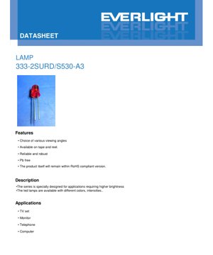
This document provides the complete technical specifications for the 333-2SURD/S530-A3 LED lamp bead. This component is a through-hole mounted, 5mm diameter LED designed to deliver reliable and robust performance for various indicator and backlight applications. The device utilizes AlGaInP (Aluminum Gallium Indium Phosphide) chip material to produce a bright red diffused light output and is encapsulated in a red diffused resin housing. Its primary design focus is to provide higher brightness, making it suitable for consumer electronics requiring clear visual signals.
This LED is supplied in tape and reel packaging, suitable for automated assembly processes, and is manufactured as a lead-free (Pb-free) component in compliance with the RoHS (Restriction of Hazardous Substances) directive. This makes it suitable for products in the global market that must adhere to modern environmental regulations.
2. Technical Parameters and Specifications
2.1 Absolute Maximum Ratings
Absolute maximum ratings define the limits that may cause permanent damage to the device. These ratings are specified at an ambient temperature (Ta) of 25°C and must not be exceeded under any operating conditions.
- Continuous Forward Current (IF):25 mA. This is the maximum direct current that can be continuously applied to the LED.
- Peak Forward Current (IFP):60 mA. This is the maximum allowable pulse forward current under the conditions of a duty cycle of 1/10 and a frequency of 1 kHz.
- Reverse Voltage (VR):5 V. Applying a reverse voltage exceeding this value may damage the LED's semiconductor junction.
- Power Dissipation (Pd):60 mW. This is the maximum power the device can dissipate.
- Operating Temperature Range (Topr):-40°C to +85°C. This is the ambient temperature range within which the LED is designed to operate.
- Storage Temperature Range (Tstg):-40°C to +100°C.
- Tsol (Soldering Temperature):260°C for 5 seconds. This is the maximum temperature and duration that the pins can withstand during wave soldering or hand soldering.
2.2 Electro-Optical Characteristics
Photometric and electrical characteristics are measured under standard test conditions of Ta=25°C and forward current (IF)=20 mA, unless otherwise specified. These parameters define the typical performance of the LED.
- Luminous intensity (Iv):100 mcd (min), 200 mcd (typ). This specifies the amount of visible light emitted by the LED. A typical value of 200 millicandelas indicates a medium-brightness output for a standard 5mm LED.
- Viewing Angle (2θ1/2):30° (typical). This is the full angle at which the luminous intensity is half of the intensity at 0° (axial). A 30° angle indicates a relatively narrow beam, suitable for directional indicator lights.
- Peak Wavelength (λp):632 nm (typical value). This is the wavelength at which the spectral power distribution of the emitted light reaches its maximum.
- Dominant Wavelength (λd):624 nm (typical value). This is the single wavelength that describes the perceived color of the light. This value places the LED in the bright red region.
- Spectral Radiant Bandwidth (Δλ):20 nm (typical). This is the spectral width of the emitted light, measured at the Full Width at Half Maximum (FWHM).
- Forward Voltage (VF):2.0 V (min), 2.4 V (typical). This is the voltage drop across the LED at the specified drive current of 20 mA. Designers must ensure the drive circuit can provide this voltage.
- Reverse Current (IR):At VR=5V, maximum 10 μA. This is the small leakage current that flows when the LED is reverse biased.
Measurement Tolerance:The datasheet specifies particular uncertainties: forward voltage ±0.1V, luminous intensity ±10%, and dominant wavelength ±1.0nm. These factors must be considered in critical design applications.
3. Performance Curve Analysis
The datasheet contains multiple characteristic curves illustrating the LED's behavior under various conditions. Understanding these curves is crucial for optimizing circuit design and thermal management.
3.1 Relative Intensity vs. Wavelength Relationship
This figure shows the spectral distribution of the emitted light. It typically peaks around the specified 632 nm (typical value), with a bandwidth (FWHM) of approximately 20 nm, confirming the monochromatic red light output characteristic of AlGaInP technology.
3.2 Directivity Pattern
This polar plot visually demonstrates a 30° viewing angle, showing how luminous intensity decreases as the observation angle deviates from the central axis. This pattern is crucial for applications requiring specific beam shapes.
3.3 Relationship between Forward Current and Forward Voltage (IV Curve)
This curve illustrates the exponential relationship between current and voltage in a diode. For this LED, at the typical operating point of 20 mA, the forward voltage is approximately 2.4V. This curve is useful for selecting an appropriate current-limiting resistor or designing a constant-current driver.
3.4 Relationship between Relative Intensity and Forward Current
This graph shows that the light output (intensity) increases with forward current, but not necessarily in a perfectly linear relationship, especially at higher currents. It emphasizes the importance of using a stable current, rather than voltage, to drive the LED in order to maintain consistent brightness.
3.5 Temperature Dependence Curve
Two key graphs illustrate the temperature effects:Relative Intensity vs. Ambient Temperature:It shows that as ambient temperature increases, light output typically decreases. This derating must be considered for applications operating in high-temperature environments.Relationship between Forward Current and Ambient Temperature:It may illustrate how forward voltage characteristics change with temperature, which is important for the stability of voltage-driven circuits.
4. Mechanical and Packaging Information
4.1 Package Dimension Drawing
This LED uses a standard 5mm round radial lead package. Key dimensions in the drawing include:
- Total diameter: 5.0mm (nominal value).
- Pin pitch: approximately 2.54mm (0.1 inch), standard through-hole package size.
- Minimum bend point: The leads must be bent at a minimum distance of 3mm from the bottom of the epoxy LED to avoid stress on the package.
- Flange height: Must be less than 1.5mm.
Unless otherwise specified on the drawing, the general dimensional tolerance is ±0.25mm. Engineers must refer to the exact dimensional drawing in the original specification for PCB layout.
4.2 Polarity Identification
The cathode (negative lead) is typically identified by two features: a flat spot on the edge of the LED plastic flange and a shorter lead length. The anode (positive lead) is longer. Correct polarity must be observed during assembly.
5. Soldering and Assembly Guide
Proper handling is crucial to ensure reliability and prevent LED damage.
5.1 Lead Forming
- The bend point must be at least 3mm away from the bottom of the epoxy LED.
- Form the pins before soldering.
- Avoid applying stress to the package; misaligned PCB holes may cause stress and lead to epoxy degradation.
- Trim the leads at room temperature.
5.2 Storage Conditions
LEDs should be stored in an environment with a temperature ≤30°C and relative humidity ≤70%. The recommended post-transport storage life is 3 months. For longer-term storage (up to one year), sealed containers with a nitrogen atmosphere and desiccant should be used.
5.3 Welding Process
Key Rules:Maintain a minimum distance of 3mm from the solder joint to the epoxy resin LED.
Manual Soldering:
- Iron tip temperature: maximum 300°C (suitable for irons up to 30W).
- Soldering time: maximum 3 seconds per pin.
Wave (DIP) soldering:
- Preheating temperature: up to 100°C (maximum 60 seconds).
- Solder bath temperature and time: up to 260°C, maximum 5 seconds.
Provides recommended soldering temperature profiles, emphasizing controlled ramp-up, peak temperature plateau, and controlled cooling stages. Avoid rapid cooling. Wave soldering or hand soldering should not exceed one cycle. After soldering, allow the LED to cool naturally to ambient temperature before subjecting it to mechanical shock or vibration.
5.4 Cleaning
If cleaning is required, use isopropyl alcohol at room temperature for no more than one minute. Do not use ultrasonic cleaning unless absolutely necessary and only after sufficient pre-qualification testing, as ultrasonic energy may damage the internal die or bond wires.
5.5 Thermal Management
Although the power consumption is low (60mW), proper thermal design is still important for extending lifespan. If the LED is used in a high-temperature environment, the operating current should be appropriately reduced. Designers should ensure adequate ventilation and avoid placing the LED near other heat-generating components.
5.6 Electrostatic Discharge (ESD) Protection
LEDs are sensitive to ESD. It is strongly recommended to take the following protective measures:
- Use grounding wrist straps and ESD protective footwear.
- Work on an ESD-safe floor and use ESD-safe containers and packaging.
- Use an ionizer to neutralize charges in the work environment.
6. Packaging and Ordering Information
6.1 Packaging Specifications
LED packaging is designed to prevent damage during transportation and handling:
- Primary packaging:Anti-static bag.
- Secondary packaging:Inner box, each box contains 5 bags.
- Tertiary packaging:Outer carton, each carton contains 10 inner boxes.
Packaging Quantity:A minimum of 200 to 500 pieces per bag. Therefore, one master carton contains 10,000 to 25,000 pieces (10 inner boxes * 5 bags * 200-500 pieces).
6.2 Labeling Instructions
Label on packaging contains key information:
- CPN:Customer Production Number.
- P/N:Production number (part number, e.g., 333-2SURD/S530-A3).
- QTY:Packaging quantity.
- CAT / Ranks:It may indicate performance grading (e.g., luminous intensity class).
- HUE:Dominant Wavelength.
- LOT No:Lot number, used for traceability.
7. Application Notes and Design Considerations
7.1 Typical Applications
As listed in the datasheet, this LED is suitable for:
- Television (status indicator, backlight).
- Monitor (Power/Activity indicator).
- Telephone (Line status, Message waiting indicator).
- Computer (Power, Hard Drive Activity Indicator).
- General panel indicators, electronic equipment, and consumer appliances requiring bright and reliable red indicator lights.
7.2 Circuit Design Considerations
Current Limiting:LEDs must always be driven with a current-limiting device, typically a resistor in series with the voltage source. The resistor value (R) can be calculated using Ohm's Law: R = (V_source - V_F) / I_F. For example, with a 5V supply, a V_F of 2.4V, and a desired I_F of 20mA: R = (5V - 2.4V) / 0.02A = 130 ohms. A standard 130Ω or 150Ω resistor is suitable, while also considering the resistor's power rating (P = I²R).
Viewing Angle:The 30° viewing angle makes this LED ideal for applications where light needs to be primarily visible from the front rather than from wide side angles.
Thermal Management in PCB Layout:Although not a high-power device, providing some copper area around the pins on the PCB helps with heat dissipation, especially when operating near maximum ratings or in a warm enclosure.
8. Technical Comparison and Differentiation
333-2SURD/S530-A3 LED has the following specific advantages:
- Chip Technology (AlGaInP):Compared to older technologies like GaAsP, it offers higher efficiency and brighter red/orange/yellow light, achieving the specified typical intensity of 200 mcd.
- Scattering Lens:The red scattering resin produces a soft, wide viewing spot without a sharp central hotspot, which is aesthetically more pleasing for status indicators.
- Robust Structure:Takardar ƙayyadaddun bayanai ta jaddada inganci da ƙarfin aiki, yana nuna cewa ƙirarta ta mayar da hankali kan tsawon rayuwa da kuma fitarwa mai daidaito.
- Daidaitawa da muhalli:Rashin gubar da kuma bin ka'idojin RoHS ma'auni ne na zamani na ƙera na'urorin lantarki amma siffa ce muhimmiya.
9. Frequently Asked Questions (FAQ)
9.1 What is the difference between Peak Wavelength (λp) and Dominant Wavelength (λd)?
Peak wavelength is the physical wavelength at which the emission spectrum is strongest. Dominant wavelength is the equivalent wavelength for perceived color, calculated based on the spectrum and human eye sensitivity (CIE color matching functions). For monochromatic red LEDs like this one, they are usually close, as seen here (632nm vs 624nm).
9.2 Can I drive this LED with a 3.3V power supply without a resistor?
A'a, yana da haɗari, zai lalata LED.LED yana kama da diode; ƙarfinsa na gaba yana da ɗan kwanciyar hankali (kusan 2.4V). Haɗa shi kai tsaye zuwa tushen 3.3V zai haifar da babban kwararar wutar lantarki, wanda ba a sarrafa shi ba (kawai ta hanyar ƙarfin ciki na tushen da juriya na LED), wanda zai wuce ƙimar 25mA na yau da kullun da sauri kuma ya haifar da gazawa mai tsanani. Koyaushe yi amfani da resistor mai iyakancewar jerin ko direban kwarara mai dorewa.
9.3 Why is a storage humidity (≤70% RH) specified?
Epoxy resin encapsulation absorbs moisture. During high-temperature soldering, this trapped moisture rapidly expands, causing internal cracks or delamination (the "popcorn" effect), which can damage the chip or bonding wires and lead to immediate or latent failures.
9.4 What does "tape and reel packaging provided" mean?
This means the LED is supplied mounted on continuous carrier tape and wound onto reels. This format is designed for automated pick-and-place machines in high-volume surface-mount production lines. Although it is a through-hole component, it can be delivered in this form for use with automated insertion machines.
10. Working Principle and Technology Trends
10.1 Basic Working Principle
LED ni diode ya semiconductor. Wakati voltage chanya inayozidi nishati ya pengo la bendi inatumika, elektroni na mashimo hujumuika katika eneo lenye utendaji (AlGaInP chip katika mfano huu). Muunganiko huu hutoa nishati kwa njia ya fotoni (mwanga). Rangi maalum ya mwanga (urefu wa wimbi) imedhamiriwa na nishati ya pengo la bendi la nyenzo ya semiconductor. AlGaInP ina pengo la bendi linalofaa kutoa mwanga mwekundu, wa machungwa na wa manjano.
10.2 Industry Background and Trends
Ingawa hii ni LED ya kawaida ya kupenya-bonde, sekta imehamia hasa kwenye vifurushi vya vifaa vilivyobandikwa kwenye uso (SMD) kama vile 0603, 0805, na 3528 katika miundo mipya mingi, kutokana na ukubwa wake mdogo, ufaao wa ununuzi wa reflow, na urefu mdogo wa wasifu. Hata hivyo, LED za kupenya-bonde kama vile duara la 5mm bado zinapendwa katika utengenezaji wa mifano, miradi ya wapenzi, vifurushi vya elimu, na matumizi ambayo yanahitaji kuunganishwa kwa mkono kwa uhakika wa juu au wakati kipengele chenyewe kinatumika kama kiashiria cha bodi kinachopita kupitia shimo la kifuniko. Teknolojia yake ya ndani AlGaInP bado ni kiwango cha LED zenye ufanisi zaidi za nyekundu, machungwa na za kahawia.
Maelezo ya Istilahi za Vipimo vya LED
Complete Interpretation of LED Technical Terminology
I. Core Indicators of Photoelectric Performance
| Terminology | Unit/Representation | Popular Explanation | Why It Matters |
|---|---|---|---|
| Luminous Efficacy | lm/W (lumens per watt) | The luminous flux emitted per watt of electrical power; higher values indicate greater energy efficiency. | It directly determines the energy efficiency rating of the luminaire and the electricity cost. |
| Luminous Flux | lm (lumen) | The total amount of light emitted by a light source, commonly known as "brightness". | Determines whether the luminaire is bright enough. |
| Viewing Angle | ° (degree), e.g., 120° | The angle at which luminous intensity drops to half, determining the beam width. | Affects the range and uniformity of illumination. |
| Correlated Color Temperature (CCT) | K (Kelvin), such as 2700K/6500K | Launin haske mai dumi ko sanyi, ƙananan ƙima sun karkata zuwa rawaya/dumi, manyan ƙima sun karkata zuwa fari/sanyi. | Yana ƙayyade yanayin hasken wuta da kuma yanayin da ya dace. |
| Color Rendering Index (CRI / Ra) | Unitless, 0–100 | The ability of a light source to reproduce the true colors of objects, with Ra≥80 being preferable. | Affects color authenticity, used in high-demand places such as shopping malls and art galleries. |
| Color tolerance (SDCM) | MacAdam ellipse step, such as "5-step" | A quantitative metric for color consistency; a smaller step number indicates better color consistency. | Ensure no color variation among luminaires from the same batch. |
| Dominant Wavelength | nm (nanometer), e.g., 620nm (red) | Wavelength values corresponding to the colors of colored LEDs. | Determines the hue of monochromatic LEDs such as red, yellow, and green. |
| Spectral Distribution | Wavelength vs. Intensity Curve | Shows the intensity distribution of light emitted by an LED at each wavelength. | Affects color rendering and color quality. |
II. Electrical Parameters
| Terminology | Symbols | Popular Explanation | Design Considerations |
|---|---|---|---|
| Forward Voltage (Forward Voltage) | Vf | The minimum voltage required to light up an LED, similar to a "starting threshold". | The driving power supply voltage must be ≥ Vf, and the voltages add up when multiple LEDs are connected in series. |
| Forward Current | If | The current value that makes the LED emit light normally. | Constant current drive is often used, as the current determines brightness and lifespan. |
| Maximum Pulse Current | Ifp | The peak current that can be withstood for a short period of time, used for dimming or flashing. | Pulse width and duty cycle must be strictly controlled, otherwise overheating damage will occur. |
| Reverse Voltage | Vr | Maximum reverse voltage that an LED can withstand; exceeding it may cause breakdown. | Reverse connection or voltage surges must be prevented in the circuit. |
| Thermal Resistance (Thermal Resistance) | Rth (°C/W) | The resistance to heat flow from the chip to the solder joint. A lower value indicates better heat dissipation. | High thermal resistance requires stronger cooling design, otherwise junction temperature rises. |
| Electrostatic Discharge Immunity (ESD Immunity) | V (HBM), such as 1000V | Electrostatic discharge immunity; a higher value indicates greater resistance to electrostatic damage. | Anti-static measures must be implemented during production, especially for high-sensitivity LEDs. |
III. Thermal Management and Reliability
| Terminology | Key Indicators | Popular Explanation | Impact |
|---|---|---|---|
| Junction Temperature | Tj (°C) | The actual operating temperature inside the LED chip. | For every 10°C reduction, the lifespan may double; excessively high temperatures lead to lumen depreciation and color shift. |
| Lumen Depreciation | L70 / L80 (hours) | The time required for the brightness to drop to 70% or 80% of its initial value. | Directly define the "useful life" of an LED. |
| Lumen Maintenance | % (e.g., 70%) | The percentage of remaining brightness after a period of use. | Characterizes the ability to maintain brightness after long-term use. |
| Color Shift | Δu′v′ or MacAdam ellipse | The degree of color change during use. | Affects the color consistency of the lighting scene. |
| Thermal Aging | Material performance degradation | Degradation of packaging materials due to long-term high temperature. | Zai iya haifar da raguwar haske, canjin launi ko gazawar bude hanya. |
IV. Kullewa da Kayan aiki
| Terminology | Nau'o'in da aka saba gani | Popular Explanation | Characteristics and Applications |
|---|---|---|---|
| Package Types | EMC, PPA, Ceramic | The housing material that protects the chip and provides optical and thermal interfaces. | EMC offers good heat resistance and low cost; ceramic provides superior heat dissipation and long lifespan. |
| Chip Structure | Front-side, Flip Chip | Chip electrode arrangement method. | Flip-chip offers better heat dissipation and higher luminous efficacy, suitable for high-power applications. |
| Phosphor coating. | YAG, silicate, nitride | Coated on the blue LED chip, partially converted to yellow/red light, mixed to form white light. | Different phosphors affect luminous efficacy, color temperature, and color rendering. |
| Lens/Optical Design | Planar, microlens, total internal reflection | Optical structure on the packaging surface, controlling light distribution. | Determines the emission angle and light distribution curve. |
V. Quality Control and Grading
| Terminology | Grading Content | Popular Explanation | Purpose |
|---|---|---|---|
| Luminous Flux Binning | Codes such as 2G, 2H | Group by brightness level, each group has a minimum/maximum lumen value. | Ensure consistent brightness for products in the same batch. |
| Voltage binning | Codes such as 6W, 6X | Grouped by forward voltage range. | Ease of driving power matching, improving system efficiency. |
| Color binning | 5-step MacAdam ellipse | Group by color coordinates to ensure colors fall within a minimal range. | Ensure color consistency to avoid uneven color within the same luminaire. |
| Color temperature grading | 2700K, 3000K, etc. | Group by color temperature, each group has a corresponding coordinate range. | Meet the color temperature requirements of different scenarios. |
VI. Testing and Certification
| Terminology | Standard/Test | Popular Explanation | Meaning |
|---|---|---|---|
| LM-80 | Lumen Maintenance Test | Long-term operation under constant temperature conditions, recording luminance attenuation data. | For estimating LED lifetime (in conjunction with TM-21). |
| TM-21 | Lifetime projection standard | Projecting lifespan under actual use conditions based on LM-80 data. | Providing scientific life prediction. |
| IESNA Standard | Illuminating Engineering Society Standard | Covers optical, electrical, and thermal test methods. | Industry-recognized testing basis. |
| RoHS / REACH | Environmental Certification | Ensure the product does not contain harmful substances (such as lead, mercury). | Entry requirements for the international market. |
| ENERGY STAR / DLC | Energy efficiency certification | Energy efficiency and performance certification for lighting products. | Commonly used in government procurement and subsidy programs to enhance market competitiveness. |