Table of Contents
- 1. Product Overview
- 2. Technical Parameter Analysis
- 2.1 Absolute Maximum Ratings
- 2.2 Electro-Optical Characteristics
- 3. Grading System Description
- 3.1 Dominant Wavelength Binning (Group A)
- 3.2 Luminous Intensity Binning
- 3.3 Forward Voltage Binning (B2 Group)
- 4. Mechanical and Packaging Information
- 4.1 Package Outline Dimensions
- 4.2 Tape and Reel Packaging
- 4.3 Moisture Sensitivity and Storage
- 5. Soldering and Assembly Guide
- 6. Application Recommendations
- 6.1 Typical Application Scenarios
- 6.2 Design Considerations
- 7. Reliability Testing
- 8. Frequently Asked Questions (Based on Technical Data)
- 9. Working Principle
- 10. Design and Use Case Studies
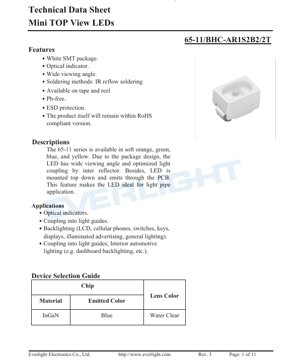
1. Product Overview
Jerin 65-11 yana wakiltar nau'in ƙananan LED na saman haske na fasahar haɗawa ta saman (SMT). Waɗannan abubuwan suna da siffa ta amfani da ƙanƙantar farin kunshe da ƙira mai haske na sama-zuwa-ƙasa, inda haske ke fitowa ta hanyar allon da'ira (PCB) kanta. Wannan takamaiman samfurin yana fitar da hasken shuɗi, tare da madaidaicin tsayin raƙuman ruwa na 468 nanometers.
Babban fa'idar wannan jerin ya haɗa da fa'idar kallon da ya fi fadi, wanda aka tsara don haɗawa mai inganci zuwa bututun jagorar haske ko bututun haske. Ƙirarsa ta haɗa da sifofi masu haɓaka aikin gani, kuma cikakke ne da ka'idojin muhalli na maras gubar (Pb-free) da RoHS. Aikin kariya na fitar da wutar lantarki (ESD) da aka gina yana kare na'urar yayin sarrafawa da haɗawa.
2. Technical Parameter Analysis
2.1 Absolute Maximum Ratings
These ratings define the limits that may cause permanent damage to the device. Operation under these conditions is not guaranteed.
- Reverse Voltage (VR):5 V
- Forward Current (IF):25 mA (Continuous)
- Peak Forward Current (IFP):100 mA (duty cycle 1/10 @ 1 kHz)
- Power consumption (Pd):110 mW
- ESD protection (HBM):2000 V
- Operating temperature (Topr):-40°C to +100°C
- Storage temperature (Tstg):-40°C to +110°C
- Soldering temperature:Reflow Soldering: Maximum 260°C, up to 10 seconds; Hand Soldering: Maximum 350°C, up to 3 seconds per pin.
2.2 Electro-Optical Characteristics
Unless otherwise specified, measurements are taken at a standard ambient temperature of 25°C and a forward current of 20 mA. Tolerance is critical for design.
- Luminous intensity (Iv):112 to 285 mcd (millicandela). Tolerance is ±11%.
- Viewing angle (2θ1/2):120 degrees (typical value). This angle defines the angular distribution range where the luminous intensity is at least half of the peak value.
- Peak wavelength (λp):468 nm (typical value).
- Dominant wavelength (λd):464.5 to 476.5 nm. Tolerance is ±1 nm.
- Spectral Bandwidth (Δλ):20 nm (typical). This indicates the spectral purity of the blue light.
- Forward Voltage (VF):2.90 zuwa 3.60 V. Tazarar shine ±0.1 V.
- Kwararar baya (IR):A ƙarancin baya na 5 V, matsakaicin 50 µA.
3. Grading System Description
LEDs are binned according to key parameters to ensure consistency across production batches. Designers can specify bins to meet application requirements for color and brightness uniformity.
3.1 Dominant Wavelength Binning (Group A)
Defines the precise hue of blue. Bins are labeled A9 through A12, where A9 represents the shortest wavelength range (464.5-467.5 nm) and A12 represents the longest wavelength range (473.5-476.5 nm).
3.2 Luminous Intensity Binning
Define the brightness grade. The grading ranges from R1 (lowest, 112-140 mcd) to S2 (highest, 225-285 mcd).
3.3 Forward Voltage Binning (B2 Group)
Define electrical characteristics. The bin numbers range from 36 to 42, corresponding to voltage ranges from 2.90-3.00 V (Bin 36) to 3.50-3.60 V (Bin 42).
4. Mechanical and Packaging Information
4.1 Package Outline Dimensions
This device features a compact SMT package size. Key dimensions include body size, lead pitch, and overall height. All unspecified tolerances are ±0.1 mm. Polarity is indicated by specific markings on the package or pin configuration, which must be noted during PCB layout and assembly.
4.2 Tape and Reel Packaging
LEDs are supplied in tape and reel format, suitable for automatic SMT assembly. Reel dimensions and tape pocket design are specified to ensure compatibility with standard SMT equipment. The standard loading quantity is 2000 pieces per reel.
4.3 Moisture Sensitivity and Storage
Components are packaged in moisture barrier aluminum foil bags with desiccant. Precautions are crucial: the bag must not be opened until the components are ready for use. Before opening, store at ≤30°C and ≤90% RH. After opening, to prevent damage from moisture during reflow soldering, it is recommended that the component's floor life be one year under conditions of ≤30°C and ≤60% RH.
5. Soldering and Assembly Guide
The primary recommended soldering method is infrared (IR) reflow soldering. The maximum allowable peak temperature is 260°C, with a duration not exceeding 10 seconds. Hand soldering is permitted but must be limited to 350°C, with a maximum of 3 seconds per pin, to prevent thermal damage to the plastic package and semiconductor chip.
6. Application Recommendations
6.1 Typical Application Scenarios
- Optical Indicator:Status indicator lights on consumer electronics, industrial control equipment, and automotive dashboards.
- Light Guide Coupling:The characteristics of top emission and wide viewing angle are very suitable for edge-lit lighting or injecting light into acrylic or polycarbonate light guide tubes, commonly used for key backlighting, panel indicator lights, and decorative lighting.
- Backlighting:Suitable for small LCD displays, keyboards, switch illumination, and general decorative or accent lighting.
- Automotive Interior Lighting:For example, applications such as dashboard switch backlighting, where reliability and color consistency are crucial.
6.2 Design Considerations
- Current limiting:The external current limiting resistor isAbsolutely essentialLED forward voltage has a negative temperature coefficient, meaning a small increase in voltage can cause a large, potentially destructive increase in current. The resistor value should be calculated based on the supply voltage and the desired forward current (typically 20 mA or less).
- Thermal Management:Although power consumption is low, ensuring the PCB provides sufficient heat dissipation, especially under high ambient temperatures or when driven at maximum continuous current, will help improve long-term reliability.
- ESD Precautions:Although the device has built-in ESD protection, standard ESD handling procedures should still be followed during assembly and installation.
7. Reliability Testing
The product undergoes a series of comprehensive reliability tests with a confidence level of 90% and a Lot Tolerance Percent Defective (LTPD) of 10%. Key tests include:
- Reflow Soldering Resistance
- Temperature Cycling (-40°C to +100°C)
- Thermal Shock
- High and Low Temperature Storage
- DC Operating Life (1000 hours at 20mA)
- High Temperature High Humidity (85°C/85% RH, 1000 hours)
These tests verify the robustness of the device under typical environmental and operational stresses encountered in electronic products.
8. Frequently Asked Questions (Based on Technical Data)
Q: What are the main advantages of the "top-emitting" design?
A: It emits light perpendicular to the PCB plane, through the circuit board itself. This is optimal for applications using light guide tubes placed directly above the LED, as it maximizes coupling efficiency and provides uniform illumination with a wide viewing angle.
Q: Ina iya haɗa wannan LED kai tsaye zuwa tushen wutar lantarki na 5V ba tare da resistor ba?
A:No.This will almost certainly damage the LED. The forward voltage is approximately 3.2V. Connecting it directly to 5V will force a current far exceeding the maximum rating, leading to immediate failure. A series resistor is essential.
Q: How to interpret the luminous intensity value?
A: Luminous intensity (in millicandelas, mcd) indicates the brightness perceived by the human eye from a specific direction. A wide viewing angle of 120° means this brightness is maintained over a very broad area, but the peak intensity value is measured along the central axis (0°).
Q: What does the binning information on the label mean?
A: The label contains codes for the luminous intensity grade (CAT), chromaticity coordinates (HUE), and forward voltage grade (REF). This allows for traceability and ensures that the components you receive have the specific optical and electrical characteristics you specified in your order, which is crucial for color matching in multi-LED applications.
9. Working Principle
The device is a semiconductor light source. It is based on an indium gallium nitride (InGaN) chip, which is a direct bandgap semiconductor material. When a forward voltage exceeding the device's threshold voltage is applied, electrons and holes recombine within the active region of the chip. In this specific material system (InGaN), this recombination process primarily releases energy in the form of photons in the blue wavelength spectrum (approximately 468 nm). The chip is encapsulated in a water-clear lens material, which helps shape the emitted light into the desired wide-angle pattern.
10. Design and Use Case Studies
Scenario: Thin-Film Switch Panel Backlighting
A designer is creating a user interface panel with multiple membrane switches, requiring blue backlighting for visibility under low-light conditions. The panel uses individual light pipes for each switch icon, routed from a central PCB.
Component Selection:The 65-11 series blue LED is selected because its top-emitting design efficiently couples to the bottom of the light pipe. The 120° wide viewing angle ensures uniform illumination of the icon area, even with imperfect alignment.
Circuit Design:The system power supply is 5V. Calculate the current-limiting resistor for each LED. Using a typical VFof 3.2V, target IFof 20mA, the resistor value is R = (5V - 3.2V) / 0.02A = 90 Ω. Select a standard 91 Ω resistor. The power dissipation on the resistor is (1.8V)^2 / 91Ω ≈ 36 mW, which is well within the rating of a standard 1/8W resistor.
PCB Layout:LED pads are precisely placed below the light guide tube mounting holes. The polarity markings on the PCB silkscreen match the LED's anode/cathode indicators. Use small thermal relief connections on the pad connected to the LED cathode (if it has a thermal pad) to aid soldering while providing some heat dissipation.
Results:The final product achieved uniform, bright blue backlighting for all switches, with extremely low power consumption, high reliability, and validation through the component-specified reliability tests.
Detailed Explanation of LED Specification Terminology
Complete Explanation of LED Technical Terminology
I. Core Indicators of Photoelectric Performance
| Terminology | Unit/Representation | Popular Explanation | Why It Is Important |
|---|---|---|---|
| Luminous Efficacy | lm/W | The luminous flux emitted per watt of electrical power, higher values indicate greater energy efficiency. | Directly determines the energy efficiency rating and electricity cost of the lighting fixture. |
| Luminous Flux | lm (Lumen) | Total light output from a light source, commonly known as "brightness". | Determines if a luminaire is bright enough. |
| Viewing Angle | ° (degrees), e.g., 120° | The angle at which luminous intensity drops to half, determining the width of the light beam. | Affects the illumination range and uniformity. |
| Color Temperature (CCT) | K (Kelvin), such as 2700K/6500K | The warmth or coolness of light color; lower values are more yellow/warm, higher values are more white/cool. | Determines the lighting atmosphere and suitable application scenarios. |
| Color Rendering Index (CRI / Ra) | Unitless, 0–100 | The ability of a light source to restore the true color of an object, Ra≥80 is recommended. | Affects color authenticity, used in high-demand places such as shopping malls and art galleries. |
| Color tolerance (SDCM) | MacAdam ellipse steps, e.g., "5-step" | A quantitative metric for color consistency; a smaller step number indicates better color consistency. | Ensure no color variation among luminaires from the same batch. |
| Dominant Wavelength | nm (nanometer), e.g., 620nm (red) | Thamani ya urefu wa wimbi inayolingana na rangi ya LED zenye rangi. | Inaamua hue ya LED moja-rangi kama nyekundu, manjano, kijani, n.k. |
| Spectral Distribution | Wavelength vs. Intensity Curve | Shows the intensity distribution of light emitted by an LED across various wavelengths. | Affects color rendering and color quality. |
II. Electrical Parameters
| Terminology | Symbol | Popular Explanation | Design Considerations |
|---|---|---|---|
| Forward Voltage | Vf | The minimum voltage required to light up an LED, similar to a "starting threshold". | The driving power supply voltage must be ≥ Vf, and the voltage accumulates when multiple LEDs are connected in series. |
| Forward Current | If | The current value that makes the LED emit light normally. | Constant current drive is often used, as the current determines brightness and lifespan. |
| Maximum Pulse Current (Pulse Current) | Ifp | Peak current that can be withstood for a short period, used for dimming or flashing. | Pulse width and duty cycle must be strictly controlled to prevent overheating and damage. |
| Reverse Voltage | Vr | The maximum reverse voltage that an LED can withstand; exceeding it may cause breakdown. | The circuit must be protected against reverse connection or voltage surges. |
| Thermal Resistance | Rth (°C/W) | The resistance to heat transfer from the chip to the solder joint; a lower value indicates better heat dissipation. | High thermal resistance requires a stronger heat dissipation design; otherwise, the junction temperature will increase. |
| Electrostatic Discharge Immunity (ESD Immunity) | V (HBM), e.g., 1000V | ESD strike resistance, the higher the value, the less susceptible to ESD damage. | Anti-static measures must be implemented during production, especially for high-sensitivity LEDs. |
III. Thermal Management and Reliability
| Terminology | Key Indicators | Popular Explanation | Impact |
|---|---|---|---|
| Junction Temperature | Tj (°C) | The actual operating temperature inside the LED chip. | For every 10°C reduction, the lifespan may double; excessively high temperatures lead to lumen depreciation and color shift. |
| Lumen Depreciation | L70 / L80 (hours) | Time required for brightness to drop to 70% or 80% of its initial value. | Directly define the "useful life" of an LED. |
| Lumen Maintenance | % (e.g., 70%) | The percentage of remaining brightness after a period of use. | Characterization of luminance maintenance capability after long-term use. |
| Color Shift | Δu′v′ or MacAdam ellipse | The degree of color change during use. | Affects the color consistency of the lighting scene. |
| Thermal Aging | Material performance degradation | Deterioration of packaging materials due to prolonged high temperatures. | May lead to decreased brightness, color changes, or open-circuit failure. |
IV. Packaging and Materials
| Terminology | Common Types | Popular Explanation | Features and Applications |
|---|---|---|---|
| Package Types | EMC, PPA, Ceramic | The housing material that protects the chip and provides optical and thermal interfaces. | EMC has good heat resistance and low cost; ceramic has excellent heat dissipation and long lifespan. |
| Chip Structure | Front Side, Flip Chip | Chip electrode arrangement method. | Flip Chip offers better heat dissipation and higher luminous efficacy, suitable for high-power applications. |
| Phosphor coating | YAG, silicate, nitride | Coated on the blue LED chip, partially converted to yellow/red light, mixed to form white light. | Different phosphors affect luminous efficacy, color temperature, and color rendering. |
| Lens/Optical Design | Planar, microlens, total internal reflection | Optical structure on the encapsulation surface, controlling light distribution. | Determines the emission angle and light distribution curve. |
V. Quality Control and Binning
| Terminology | Binning Content | Popular Explanation | Purpose |
|---|---|---|---|
| Luminous Flux Binning | Codes such as 2G, 2H | Group by brightness level, each group has a minimum/maximum lumen value. | Ensure consistent brightness for products within the same batch. |
| Voltage binning | Codes such as 6W, 6X | Grouped by forward voltage range. | Facilitates driver power matching and improves system efficiency. |
| Color binning | 5-step MacAdam ellipse | Group by color coordinates to ensure colors fall within an extremely small range. | Ensure color consistency to avoid color unevenness within the same luminaire. |
| Color temperature binning | 2700K, 3000K, etc. | Group by color temperature, each group has a corresponding coordinate range. | Meet the color temperature requirements of different scenarios. |
VI. Testing and Certification
| Terminology | Standard/Test | Popular Explanation | Significance |
|---|---|---|---|
| LM-80 | Lumen Maintenance Test | Long-term operation under constant temperature conditions, recording data on luminance attenuation. | Used for estimating LED lifespan (combined with TM-21). |
| TM-21 | Life Prediction Standard | Life estimation under actual use conditions based on LM-80 data. | Provide scientific life prediction. |
| IESNA Standard | Illuminating Engineering Society Standard | Covering optical, electrical, and thermal testing methods. | Industry-recognized testing basis. |
| RoHS / REACH | Environmental Certification | Ensure the product does not contain hazardous substances (e.g., lead, mercury). | Conditions for market entry into the international market. |
| ENERGY STAR / DLC | Energy efficiency certification | Energy Efficiency and Performance Certification for Lighting Products. | Commonly used in government procurement and subsidy programs to enhance market competitiveness. |