Table of Contents
- 1. Product Overview
- 2. Detailed Technical Parameters
- 2.1 Absolute Maximum Ratings
- 2.2 Optoelectronic Characteristics
- 3. Grading System Description
- 3.1 Luminous Intensity Binning
- 3.2 Dominant Wavelength Binning
- 3.3 Forward Voltage Binning
- 4. Performance Curve Analysis
- 5. Mechanical and Packaging Information
- 5.1 Package Dimensions
- 6. Soldering and Assembly Guide
- 6.1 Pin Forming
- 6.2 Storage Conditions
- 6.3 Welding Process
- 7. Packaging and Ordering Information
- 7.1 Packaging Specifications
- 7.2 Label Information
- 8. Application Recommendations
- 8.1 Typical Application Scenarios
- 8.2 Design Considerations
- 9. Technical Comparison and Differentiation
- 10. Frequently Asked Questions (Based on Technical Parameters)
- 10.1 What is the difference between Peak Wavelength and Dominant Wavelength?
- 10.2 Can I continuously drive this LED at 30mA to achieve maximum brightness?
- 10.3 Yaya yin oda yadda ake fassara lambobin rarrabuwa (misali H1-2, 1b)?
- 10.4 Me ya sa iyakar rayuwar ajiya ta kasance watanni 3? Menene zai faru idan an wuce wannan lokacin?
- 11. Nazarin Shari'ar Zane
- 12. Ayyukan Aiki
- 13. Technology Trends
1. Product Overview
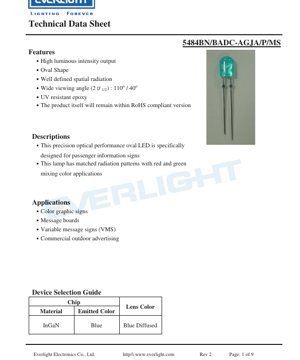
This document details the specifications of an elliptical LED with precision optical performance. The device is specifically designed for passenger information signs and similar display system applications. Its core design philosophy focuses on providing a well-defined spatial radiation pattern, which is crucial for achieving uniform illumination and color mixing in graphic displays.
This LED features high luminous intensity output, making it suitable for outdoor and high ambient light environments. Its elliptical lens is a key differentiating feature, creating an asymmetric viewing angle optimized for horizontal signage. This characteristic, combined with a wide viewing angle of 110 degrees (one axis) and 40 degrees (vertical axis), ensures good visibility from various angles. The encapsulation material uses UV-resistant epoxy resin, enhancing long-term reliability and color stability under sunlight exposure, which is critical for outdoor advertising and variable message signs.
2. Detailed Technical Parameters
2.1 Absolute Maximum Ratings
The device is designed to operate within strict electrical and thermal limits to ensure reliability. Absolute maximum ratings define thresholds beyond which permanent damage may occur.
- Forward current (IF):30 mA (DC). This is the maximum continuous current that can be applied.
- Pulse Forward Current (IFP):100 mA, allowed under pulse conditions with a duty cycle of 1/10 and a frequency of 1kHz. This allows for short-duration high-brightness operation.
- Reverse Voltage (VR):5 V. Exceeding this voltage under reverse bias may damage the LED junction.
- Power Dissipation (Pd):100 mW. This parameter limits the total electrical power that can be converted into heat.
- Operating and Storage Temperature:The device can operate at -40°C to +85°C and can be stored at -40°C to +100°C.
- Soldering temperature:Can withstand 260°C for up to 5 seconds, compatible with standard lead-free soldering processes.
- Electrostatic Discharge (ESD):Can withstand 1000V (Human Body Model), indicating a medium level of ESD protection. It is still recommended to follow proper ESD handling procedures.
2.2 Optoelectronic Characteristics
These parameters are measured under standard test conditions (Ta=25°C, IF=20mA), defines the core performance of the LED.
- Luminous Intensity (IV):ranges from a minimum of 720 mcd to a maximum of 1450 mcd. Typical values fall within this range, providing high brightness.
- Viewing Angle (2θ1/2):Asymmetric, 110° x 40°. The larger 110° angle is typically used for a wide horizontal field of view, while the 40° angle provides a more focused vertical beam.
- Peak Wavelength (λp):Typical value 468 nm, indicating the point of maximum spectral power emission.
- Dominant Wavelength (λd):Ranges from 465 nm to 475 nm. This defines the color of light perceived by the human eye (blue).
- Spectral Half Width (Δλ):Typical value 26 nm. This measures spectral purity; a narrower width indicates a more saturated blue.
- Forward Voltage (VF):At 20mA, the range is from 2.8V to 3.6V. This is crucial for driving circuit design to ensure proper current regulation.
- Reverse Current (IR):At VR=5V, the maximum is 50 μA, indicating good junction quality.
3. Grading System Description
To ensure color and brightness consistency in production, LEDs are sorted into different bins based on key parameters.
3.1 Luminous Intensity Binning
Based on the luminous intensity measured at 20mA, LEDs are classified into four grades (G2, H1, H2, J1).
- G2:720 ~ 860 mcd
- H1:860 ~ 1030 mcd
- H2:1030 ~ 1210 mcd
- J1:1210 ~ 1450 mcd
Measurement uncertainty is ±10%. Designers can select specific bins to achieve particular brightness levels or uniformity of the display.
3.2 Dominant Wavelength Binning
Color consistency is managed through four wavelength grades (1a, 1b, 2a, 2b).
- 1a:465.0 ~ 467.5 nm
- 1b:467.5 ~ 470.0 nm
- 2a:470.0 ~ 472.5 nm
- 2b:472.5 ~ 475.0 nm
The measurement uncertainty is ±1.0 nm. This binning is crucial for applications requiring precise color matching, such as when blue is mixed with other colors in full-color signage.
3.3 Forward Voltage Binning
The forward voltage is divided into four grades (0, 1, 2, 3) to assist drive design and power management.
- 0:2.8 ~ 3.0 V
- 1:3.0 ~ 3.2 V
- 2:3.2 ~ 3.4 V
- 3:3.4 ~ 3.6 V
The measurement uncertainty is ±0.1V. Using LEDs from the same voltage bin can simplify the calculation of current-limiting resistors in series or parallel arrays.
4. Performance Curve Analysis
The datasheet references typical photoelectric characteristic curves. While specific graphs are not provided in the text, standard curves for such LEDs typically include:
- Relative Luminous Intensity vs. Forward Current (I-V Curve):It shows how light output increases with current, typically in an approximately linear relationship before reaching the maximum rated current. It highlights the importance of constant current drive for stable brightness.
- Relative Luminous Intensity vs. Ambient Temperature:It demonstrates the thermal derating of light output. Luminous intensity typically decreases as junction temperature increases, which is a key consideration for thermal management in enclosed signage.
- Forward Voltage vs. Junction Temperature:VFThe negative temperature coefficient of V is shown. The forward voltage decreases with increasing temperature, which may affect the performance of drive circuits based on simple resistors.
- Spectral distribution:A plot of relative intensity versus wavelength shows a peak at approximately 468 nm and a full width at half maximum of 26 nm, confirming blue light emission.
- Perspective Mode:Polar plot illustrating the asymmetric radiation pattern (110° x 40°), crucial for the optical design that directs light to the desired location in the identifier.
5. Mechanical and Packaging Information
5.1 Package Dimensions
This LED employs a specific elliptical lens package. The key dimensional specifications in the datasheet include:
- All dimensions are in millimeters (mm).
- Standard tolerance is ±0.25 mm unless otherwise specified.
- Maximum resin protrusion under the flange is 1.5 mm.
- After the connecting rib is cut, this part will expose bare copper alloy. If not properly protected during assembly or coating of the protective layer, this area may be susceptible to oxidation.
Precise dimensional drawings are referenced but not detailed in the text. This package is designed for through-hole mounting (DIP).
6. Soldering and Assembly Guide
6.1 Pin Forming
- Bending must occur at least 3 mm from the bottom of the epoxy lamp bead to prevent stress on the internal chip and bonding wires.
- Pin forming must be completedSoldering processbefore.
- Avoid applying stress to the LED package during the bending process.
- Cut the lead frame at room temperature. High-temperature cutting may cause thermal shock.
- PCB holes must be precisely aligned with LED pins. Misalignment causing pin stress will degrade the performance of the epoxy and the LED.
6.2 Storage Conditions
- Yanar da Ajiya da ake ba da shawara: ≤30°C kuma ≤70% zafi na dangi (RH).
- Mafi dadewar rayuwar ajiya a cikin wannan yanayin: watanni 3 daga lokacin jigilar kaya.
- For longer storage (up to 1 year), place the LED in a sealed container filled with nitrogen gas and containing a desiccant.
- Avoid rapid temperature changes under high humidity to prevent condensation, which can lead to moisture ingress and cause failures during soldering ("popcorn" effect).
6.3 Welding Process
Provides detailed recommendations for manual soldering and wave soldering.
- General Rules:Maintain a minimum distance of 3 mm from the solder joint to the epoxy resin LED.
- Manual soldering:Soldering iron tip temperature ≤300°C (suitable for a maximum 30W iron). Soldering time per pin ≤3 seconds.
- Wave/DIP soldering:
- Preheating temperature: ≤100°C (Duration ≤60 seconds).
- Solder pot temperature: ≤260°C.
- Soldering time in pot: ≤5 seconds.
- Avoid applying stress to the leads when the LED is at high temperature.
- Do not solder the same LED more than once (wave soldering or hand soldering).
- After soldering, protect the epoxy lamp bead from mechanical shock/vibration until the LED cools to room temperature.
- Avoid rapid cooling from the peak soldering temperature.
The recommended soldering temperature profile is referenced, typically showing ramp-up, preheat, peak temperature (260°C), and controlled cooling process.
7. Packaging and Ordering Information
7.1 Packaging Specifications
LEDs are packaged in anti-static materials with clear labels.
- Primary Packaging:500 pieces per anti-static bag.
- Secondary Packaging:5 bags packed into one inner box (total 2,500 pieces).
- Tertiary Packaging:10 inner boxes are packed into one master carton (25,000 pieces in total).
7.2 Label Information
Labels on bags and cartons contain key information for traceability and correct application:
- CPN (Customer Part Number):Customer's internal reference number.
- P/N (Production Part Number):Manufacturer Part Number (e.g., 5484BN/BADC-AGJA/P/MS).
- QTY (Quantity):Number of pieces inside the package.
- CAT (Category):Combination grade code for luminous intensity and forward voltage (e.g., H1-2).
- HUE:The grade code for dominant wavelength binning (e.g., 1b).
- REF (Reference):Additional reference information.
- LOT No:Production batch number traceable.
- Production Place:Indicate country of production.
8. Application Recommendations
8.1 Typical Application Scenarios
As specified, this LED is designed for the following applications:
- Color graphic signs and information boards:Its high intensity and oval beam pattern make it ideal for sign backlighting or direct illumination, ensuring readability.
- Variable Message Signs (VMS):Used on highways, airports, and public transport systems. The grading system ensures color and brightness consistency on large multi-LED displays.
- Commercial Outdoor Advertising:UV-resistant epoxy resin and robust design ensure long-term reliability in harsh outdoor environments exposed to sunlight and weather.
- Passenger Information Signage:A specific spatial radiation pattern is designed to mix with red and green LEDs, creating various colors in full-color displays.
8.2 Design Considerations
- Drive Circuit:Use a constant current driver set to 20mA (or lower to reduce brightness/power consumption) to ensure stable operation and long life. When designing the series string, consider VFBinning.
- Thermal Management:Ko kowane LED yana amfani da wutar lantarki kawai 100mW, tsararrun LED masu yawa a cikin alamun da aka rufe suna haifar da zafi mai yawa. Tabbatar da isasshiyar iska ko hanyoyin sanyaya, don kiyaye zafin jiki a cikin iyakokin aminci, don kiyaye fitowar haske da tsawon rayuwa.
- Optical Design:Use a viewing angle of 110° x 40°. Orient the LED so that the 110° axis covers the required horizontal viewing area. If necessary, use secondary optics (diffusers, lenses) to further shape the beam.
- ESD Protection:Although the ESD rating is 1kV, standard ESD prevention measures must still be implemented during handling and assembly.
9. Technical Comparison and Differentiation
Although the datasheet does not directly compare it with other models, the key differentiating features of this LED can be inferred:
- Elliptical lens vs. Standard circular lens:Main differentiation point. The elliptical lens produces a rectangular radiation pattern, which is more efficient for illuminating rectangular sign areas compared to the circular spot from a round lens, reducing light waste.
- Matched radiation pattern for color mixing:The datasheet clearly states the radiation pattern is suitable for red/green/blue mixing applications. This indicates careful optical design to ensure uniform color mixing across different viewing angles within an RGB pixel cluster.
- High intensity binning:Provides a grade of up to 1450mcd, offering a high-brightness option for sunlight-readable applications.
- UV-Resistant Epoxy:Crucial for outdoor longevity, it prevents the encapsulation material from yellowing and the light transmittance from decreasing over time.
10. Frequently Asked Questions (Based on Technical Parameters)
10.1 What is the difference between Peak Wavelength and Dominant Wavelength?
Peak Wavelength (λp~468 nm)It is the wavelength at which the LED emits its maximum optical power.Dominant Wavelength (λd465-475 nm)It is the wavelength of monochromatic light perceived by the human eye as having the same color as the LED. Dominant wavelength is more relevant for color specifications in displays.
10.2 Can I continuously drive this LED at 30mA to achieve maximum brightness?
Yes, 30mA is the absolute maximum continuous forward current. However, operating at the maximum rating generates more heat and may accelerate luminous flux degradation over time. For optimal lifetime and reliability, it is recommended to drive at or below the test current of 20mA, unless high brightness is critical and thermal management is excellent.
10.3 Yaya yin oda yadda ake fassara lambobin rarrabuwa (misali H1-2, 1b)?
The "CAT" code (e.g., H1-2) combines the luminous intensity bin (H1 = 860-1030 mcd) and the forward voltage bin (2 = 3.2-3.4V). The "HUE" code (e.g., 1b = 467.5-470.0 nm) specifies the dominant wavelength bin. Specifying these bins ensures you receive LEDs with tightly grouped performance characteristics, enabling consistent display results.
10.4 Me ya sa iyakar rayuwar ajiya ta kasance watanni 3? Menene zai faru idan an wuce wannan lokacin?
The 3-month limit under standard factory conditions (≤30°C/70%RH) is to prevent moisture absorption through the plastic package. After 3 months, the moisture level may exceed the safe limit for soldering, posing a risk of internal delamination or cracking during high-temperature reflow ("popcorn" effect). For longer-term storage, a dry nitrogen-filled environment prevents moisture ingress, extending the safe storage period to one year.
11. Nazarin Shari'ar Zane
Scenario: Design a High-Brightness Outdoor Variable Message Sign (VMS)
- Demand Analysis:The label must be readable in sunlight, operate at temperatures from -20°C to +60°C, and have a uniform color appearance.
- LED Selection:This oval blue LED was chosen for its high intensity (select J1 bin for maximum brightness), UV-resistant epoxy suitable for outdoor use, and radiation pattern matching its red and green partner LEDs for color mixing.
- Electrical Design:The LEDs are arranged in series strings. The driver is a constant-current type, set to 18mA (slightly below 20mA for margin). The worst-case VF(3.6V from bin 3) is used to calculate the minimum driver voltage required per series string.
- Thermal Design:PCB uses Metal Core PCB (MCPCB) to effectively conduct heat away from the LED array. Thermal simulation is performed to ensure the LED junction temperature remains below 85°C at the maximum ambient temperature.
- Optical and Mechanical Design:LED yinang, 110° axis horizontal align to marker. Secondary diffuser plate placed above array, merging individual LED spots into smooth, uniform light panel.
- Procurement and Assembly:Specify binning code (e.g., intensity J1 bin, wavelength 2a bin) when ordering LEDs to ensure consistency across all production batches. Strictly adhere to soldering temperature profile and storage guidelines during assembly.
12. Ayyukan Aiki
This LED is based on an InGaN (Indium Gallium Nitride) semiconductor chip. When a forward voltage exceeding the diode's threshold (approximately 2.8-3.6V) is applied, electrons and holes are injected into the active region of the semiconductor. They recombine, releasing energy in the form of photons. The specific composition of the InGaN alloy determines the bandgap energy, which in turn defines the wavelength of the emitted light—in this case, within the blue spectrum (approximately 468 nm). The elliptical epoxy resin lens surrounding the chip acts as the primary optical element, refracting and shaping the emitted light into the desired 110° x 40° radiation pattern.
13. Technology Trends
LEDs for signage continue to evolve. While this datasheet represents a mature through-hole (DIP) product, the overall industry trends include:
- Efficiency improvement (lm/W):Updated chip technology and phosphors allow for higher light output at the same or lower drive currents, reducing power consumption and thermal load.
- Adoption of Surface Mount Devices (SMD):Compared to traditional DIP packaging, SMD packaging allows for higher density, automated assembly, and typically offers better thermal paths, although DIP remains relevant in some high-power or legacy designs.
- Color Rendering and Gamut Improvement:Ukuvuselelwa kwezinto zokwakha i-semiconductor kanye nezinhlelo ze-phosphor kwenze i-LED ibe ne-spectrum peak encane futhi inombala ogcwele ngokwanele, okwandise i-gamut yombala yezibonisi ezinombala wonke.
- Ukuhlanganiswa kwezici ezihlakaniphile:Amanye ama-LED esimanje wamakhefu ane-driver afakiwe ngaphakathi (IC-driven LED) noma okungafinyeleleka, okwenza ukuklanywa kohlelo kube lula.
- Ukuthembeka okuthuthukisiwe kanye nempilo yokusebenza:Continuous improvements in packaging materials, such as the use of more robust silicone instead of epoxy in some high-power applications, lead to longer operational life and better tolerance to harsh environments.
The product described in this specification is, in this context, a specialized component optically optimized for specific application areas where its elliptical beam pattern and high-intensity output provide distinct advantages.
Detailed Explanation of LED Specification Terminology
Complete Interpretation of LED Technical Terminology
I. Core Indicators of Photoelectric Performance
| Terminology | Unit/Representation | Popular Explanation | Why It Matters |
|---|---|---|---|
| Luminous Efficacy | lm/W (lumens per watt) | The luminous flux emitted per watt of electrical power; higher values indicate greater energy efficiency. | It directly determines the energy efficiency rating of the luminaire and the electricity cost. |
| Luminous Flux | lm (lumen) | The total amount of light emitted by a light source, commonly known as "brightness". | Determines whether the luminaire is bright enough. |
| Viewing Angle | ° (degree), e.g., 120° | The angle at which luminous intensity drops to half, determining the beam width. | Affects the range and uniformity of illumination. |
| Color Temperature (CCT) | K (Kelvin), such as 2700K/6500K | Haske launin dumi da sanyi, ƙananan ƙima sun karkata zuwa rawaya/dumi, manyan ƙima sun karkata zuwa fari/sanyi. | Yana ƙayyade yanayin hasken wuta da kuma yanayin da ya dace. |
| Color Rendering Index (CRI / Ra) | Unitless, 0–100 | The ability of a light source to reproduce the true colors of objects, with Ra≥80 being preferable. | Affects color fidelity, used in high-demand places such as shopping malls and art galleries. |
| Color tolerance (SDCM) | MacAdam ellipse step, such as "5-step" | A quantitative indicator of color consistency; a smaller step number indicates better color consistency. | Ensure no color difference among luminaires from the same batch. |
| Dominant Wavelength | nm (nanometer), e.g., 620nm (red) | Wavelength values corresponding to the colors of colored LEDs. | Determines the hue of monochromatic LEDs such as red, yellow, and green. |
| Spectral Distribution | Wavelength vs. Intensity Curve | Shows the intensity distribution of light emitted by an LED at each wavelength. | Affects color rendering and color quality. |
II. Electrical Parameters
| Terminology | Symbol | Popular Explanation | Design Considerations |
|---|---|---|---|
| Forward Voltage (Forward Voltage) | Vf | The minimum voltage required to light up an LED, similar to a "starting threshold". | The driving power supply voltage must be ≥ Vf, and the voltages add up when multiple LEDs are connected in series. |
| Forward Current | If | The current value that makes the LED emit light normally. | Constant current drive is often used, as the current determines brightness and lifespan. |
| Maximum Pulse Current | Ifp | The peak current that can be withstood for a short period of time, used for dimming or flashing. | Pulse width and duty cycle must be strictly controlled to prevent overheating damage. |
| Reverse Voltage | Vr | Maximum reverse voltage that an LED can withstand; exceeding it may cause breakdown. | Reverse connection or voltage surges must be prevented in the circuit. |
| Thermal Resistance (Thermal Resistance) | Rth (°C/W) | The resistance to heat flow from the chip to the solder joint. A lower value indicates better heat dissipation. | High thermal resistance requires stronger cooling design, otherwise junction temperature rises. |
| Electrostatic Discharge Immunity (ESD Immunity) | V (HBM), such as 1000V | Electrostatic discharge immunity; a higher value indicates greater resistance to damage from static electricity. | Anti-static measures must be implemented during production, especially for high-sensitivity LEDs. |
III. Thermal Management and Reliability
| Terminology | Key Indicators | Popular Explanation | Impact |
|---|---|---|---|
| Junction Temperature | Tj (°C) | The actual operating temperature inside the LED chip. | For every 10°C reduction, the lifespan may double; excessively high temperatures cause lumen depreciation and color shift. |
| Lumen Depreciation | L70 / L80 (hours) | The time required for the brightness to drop to 70% or 80% of its initial value. | Directly define the "useful life" of an LED. |
| Lumen Maintenance | % (e.g., 70%) | The percentage of remaining brightness after a period of use. | Characterizes the ability to maintain brightness after long-term use. |
| Color Shift | Δu′v′ or MacAdam ellipse | The degree of color change during use. | Affects the color consistency of the lighting scene. |
| Thermal Aging | Material performance degradation | Degradation of packaging materials due to prolonged high temperatures. | Zai iya haifar da raguwar haske, canjin launi ko gazawar bude hanya. |
IV. Kullewa da Kayan aiki
| Terminology | Nau'o'in gama gari | Popular Explanation | Characteristics and Applications |
|---|---|---|---|
| Package Types | EMC, PPA, Ceramic | The housing material that protects the chip and provides optical and thermal interfaces. | EMC offers good heat resistance and low cost; ceramic provides superior heat dissipation and long lifespan. |
| Chip Structure | Front-side, Flip Chip | Chip electrode arrangement method. | Flip-chip offers better heat dissipation and higher luminous efficacy, suitable for high-power applications. |
| Phosphor coating. | YAG, silicate, nitride | Coated on the blue LED chip, partially converted to yellow/red light, mixed to form white light. | Different phosphors affect luminous efficacy, color temperature, and color rendering. |
| Lens/Optical Design | Flat, microlens, total internal reflection | Optical structure on the packaging surface, controlling light distribution. | Determines the emission angle and light distribution curve. |
V. Quality Control and Grading
| Terminology | Grading Content | Popular Explanation | Purpose |
|---|---|---|---|
| Luminous Flux Binning | Codes such as 2G, 2H | Group by brightness level, each group has a minimum/maximum lumen value. | Ensure consistent brightness for products in the same batch. |
| Voltage binning | Code such as 6W, 6X | Grouped by forward voltage range. | Facilitating driver power matching to enhance system efficiency. |
| Color binning | 5-step MacAdam ellipse | Group by color coordinates to ensure colors fall within a minimal range. | Ensure color consistency to avoid uneven colors within the same luminaire. |
| Color temperature grading | 2700K, 3000K, etc. | Group by color temperature, each group has a corresponding coordinate range. | Meet the color temperature requirements of different scenarios. |
VI. Testing and Certification
| Terminology | Standard/Test | Popular Explanation | Meaning |
|---|---|---|---|
| LM-80 | Lumen Maintenance Test | Long-term operation under constant temperature conditions, recording brightness attenuation data. | For estimating LED lifetime (in conjunction with TM-21). |
| TM-21 | Lifetime projection standard | Estimating lifespan under actual usage conditions based on LM-80 data. | Providing scientific life prediction. |
| IESNA Standard | Illuminating Engineering Society Standard | Covers optical, electrical, and thermal test methods. | Industry-recognized testing basis. |
| RoHS / REACH | Environmental Certification | Ensure the product does not contain harmful substances (e.g., lead, mercury). | Entry requirements for the international market. |
| ENERGY STAR / DLC | Energy efficiency certification | Energy efficiency and performance certification for lighting products. | Commonly used in government procurement and subsidy programs to enhance market competitiveness. |