Kasidu
- 1. Product Overview
- 2. Technical Parameter Analysis
- 2.1 Absolute Maximum Ratings
- 2.2 Electro-Optical Characteristics
- 3. Grading System Description
- 3.1 Luminous Intensity Binning
- 3.2 Dominant Wavelength Binning
- 3.3 Forward Voltage Binning
- 4. Performance Curve Analysis
- 4.1 Relative Intensity vs. Wavelength
- 4.2 Directivity Pattern
- 4.3 Forward Current vs. Forward Voltage (I-V Curve)
- 4.4 Relative Intensity vs. Forward Current
- 4.5 Thermal Characteristics
- 5. Mechanical and Packaging Information
- 5.1 Package Size
- 5.2 Polarity Identification
- 6. Welding and Assembly Guide
- 7. Packaging and Ordering Information
- 7.1 Moisture-Proof Packaging
- 7.2 Tape and Reel Specification
- 7.3 Package Quantity
- 7.4 Label Description and Part Number
- 8. Application Recommendations
- 8.1 Typical Application Scenarios
- 8.2 Design Considerations
- 9. Technical Comparison and Differentiation
- 10. Frequently Asked Questions (Based on Technical Parameters)
- 11. Design Use Case Studies
- 12. Technical Principle Introduction
- 13. Teknoloji Trendleri ve Arka Plan
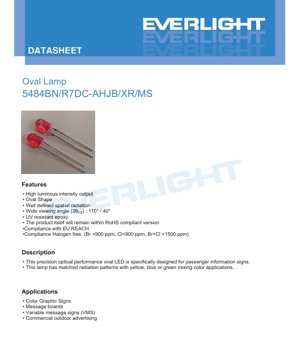
1. Product Overview
This document elaborates on the specifications of a high-performance elliptical LED lamp bead. The primary design objective of this component is to serve as a reliable and efficient light source for passenger information systems and various signage applications. Its unique optical design and form factor are specifically tailored to meet the special requirements for clearly visible displays in both indoor and outdoor environments.
The core advantages of this LED include its high luminous intensity output, ensuring excellent visibility even under well-lit conditions. The elliptical shape and meticulously designed radiation pattern provide a defined spatial light distribution, which is crucial for uniform illumination of signage panels. Furthermore, the component is designed for long life, utilizing UV-resistant epoxy resin, and adheres to major environmental and safety standards such as RoHS, EU REACH, and halogen-free requirements, making it suitable for the global market and sustainable design practices.
The target market encompasses manufacturers of transportation infrastructure equipment, commercial advertising systems, and public information displays. Its primary applications include color graphic signs, information panels, and Variable Message Signs (VMS), where consistent color mixing (especially with yellow, blue, or green components) and reliable performance are critical.
2. Technical Parameter Analysis
2.1 Absolute Maximum Ratings
Na'urar an yi ta ne don aiki cikin aminci a cikin iyakar iyakar da ke ƙasa. Wucewa waɗannan ƙimar na iya haifar da lalacewa na dindindin.
- Ƙarfin lantarki na baya (VR):5 V. Wannan yana bayyana matsakaicin ƙarfin lantarki na baya da za a iya amfani da shi akan tashar LED.
- Forward current (IF):50 mA (continuous). The recommended maximum continuous current during normal operation.
- Peak forward current (IFP):160 mA. Wannan shine matsakaicin ƙarfin bugun jini da aka yarda, yawanci ana ƙayyade shi a cikin mitar 1 kHz tare da aikin 1/10. Yana da mahimmanci ga ƙira da ta ƙunshi yawan amfani ko ɗan gajeren bugun jini mai ƙarfi.
- Amfani da wutar lantarki (Pd):120 mW. Matsakaicin ƙarfin da za'a iya ɓata a cikin kunshe ba tare da wuce iyakokin zafin jiki ba, ana ƙididdige shi azaman samfurin ƙarfin lantarki da kuma ƙarfin halin yanzu.
- Yanayin aiki (Topr):-40°C to +85°C. The ambient temperature range within which the device is guaranteed to operate normally.
- Storage temperature (Tstg):-40°C to +100°C. The safe temperature range for storage when the device is not powered.
- Junction Temperature (Tj):110°C. The maximum allowable temperature for the semiconductor junction inside the LED.
- Soldering Temperature (Tsol):260°C for 5 seconds. This defines the reflow soldering profile tolerance, which is critical for PCB assembly processes.
2.2 Electro-Optical Characteristics
These parameters are measured under standard test conditions (Ta=25°C, IF=20mA), defines the core performance of the LED.
- Luminous Intensity (Iv):1220 - 2040 mcd (millicandela). This indicates the amount of visible light emitted in a specific direction. The wide range is managed through a binning system (see Section 3).
- Viewing Angle (2θ1/2):110° (X-axis) / 40° (Y-axis). This asymmetric elliptical beam pattern is a key feature. The wide 110° viewing angle is ideal for horizontal viewing of signage, while the narrower 40° vertical viewing angle helps concentrate the light, improving efficiency for the viewer.
- Peak Wavelength (λp):632 nm (typical). The wavelength at which the spectral power distribution reaches its maximum value.
- Dominant Wavelength (λd):619 - 628 nm. This defines the perceived color of the light, located in the red spectrum. It is also managed by binning.
- Spectral Radiant Bandwidth (Δλ):20 nm (typical). The width of the emission spectrum at half the maximum intensity (FWHM).
- Forward Voltage (VF):1.8 - 2.4 V. The voltage drop across the LED under test current drive. This range is managed through binning and influences the design of the drive circuit.
- Reverse Current (IR):10 μA (max) at VR=5V. Measures the leakage current of the diode in the off state.
3. Grading System Description
To ensure performance consistency in mass production, LEDs are sorted into different bins based on key parameters. This allows designers to select components that meet their specific brightness and color requirements.
3.1 Luminous Intensity Binning
Matsakaicin matsayi an bayyana shi da ƙimar alƙawari na ±10%.
- Matsakaicin matsayi H2:1220 - 1440 mcd
- Gear J1:1440 - 1720 mcd
- Gear J2:1720 - 2040 mcd
Selecting a higher gear (e.g., J2) ensures a higher minimum brightness, which may be necessary for applications requiring maximum visibility or to compensate for optical losses in sign diffusers.
3.2 Dominant Wavelength Binning
Grading ensures color consistency with a strict tolerance of ±1 nm.
- Grade 1:619 - 622 nm
- Gear 2:622 - 625 nm
- Gear 3:625 - 628 nm
For color mixing applications (e.g., used with yellow or green LEDs), selecting LEDs from the same or adjacent wavelength bins is crucial to achieve the desired final color with minimal variation between units.
3.3 Forward Voltage Binning
Bin tolerance is ±0.1V.
- Grade 1:1.8 - 2.0 V
- Gear 2:2.0 - 2.2 V
- Gear 3:2.2 - 2.4 V
Amfani da LED daga matakin wutar lantarki iri ɗaya yana sauƙaƙa lissafin resistor mai iyakancewar kwarara a cikin jeri ko tsararrun layi daya, yana tabbatar da rarraba kwarara da haske mafi daidaito.
4. Performance Curve Analysis
The provided characteristic curves reveal the behavior of LEDs under different conditions.
4.1 Relative Intensity vs. Wavelength
This spectral distribution curve confirms a monochromatic red light output centered at 632 nm with a typical bandwidth of 20 nm. The narrow spectrum is characteristic of AlGaInP material technology, providing ideal saturated color purity for signage applications.
4.2 Directivity Pattern
Taswirar hasken polar ta nuna a bayyane kusurwar hangen nesa mara daidaituwa na 110° x 40°. Taswirar tana nuna ellipse mai bayyanannen ma'ana, tana tabbatar da hasken sararin samaniya da aka yi iƙirari a cikin siffofi. An ƙera wannan tsarin don dacewa da matsakaicin rabo na faɗi zuwa tsayi na sassan nuni na bayanai.
4.3 Forward Current vs. Forward Voltage (I-V Curve)
This curve shows the typical exponential relationship of a diode. The forward voltage increases with the current. Designers use this curve to determine the operating point and design appropriate drive circuits (constant current drive is recommended for LEDs). This curve also helps in understanding the dynamic resistance of the device.
4.4 Relative Intensity vs. Forward Current
This curve shows the LED's light output (luminous intensity) as a function of drive current. It is typically linear within a certain range but saturates at higher currents due to thermal effects and efficiency droop. Operating at or below the recommended value of 50mA ensures optimal efficiency and lifetime.
4.5 Thermal Characteristics
AboutRelative Intensity vs. Ambient Temperature和Forward Current vs. Ambient TemperatureThe curves are crucial for thermal management. They show that luminous intensity decreases as ambient temperature rises, which is a common phenomenon for all LEDs. Conversely, for constant voltage drive, the forward current typically increases with temperature due to the negative temperature coefficient of VFThis highlights the importance of constant current drivers for maintaining stable performance across the temperature range.
5. Mechanical and Packaging Information
5.1 Package Size
This LED is provided in a Surface-Mount Device (SMD) package. Key dimensional specifications include:
- Unless otherwise specified, all dimensions are in millimeters.
- Standard tolerance of ±0.25mm applies to most dimensions.
- The maximum allowable resin protrusion under the component flange is 1.5mm, which is important for PCB clearance calculations.
- The datasheet illustrates two variants: one with a stop feature and one without. The stop feature may aid placement accuracy or provide a physical locating point during assembly.
The detailed drawing specifies pin pitch, body dimensions, and overall height, which are crucial for creating an accurate PCB footprint and ensuring correct placement by the pick-and-place machine.
5.2 Polarity Identification
Although not explicitly detailed in the extracted text, standard LED packages typically use visual indicators such as notches, flat edges on the lens, or differently shaped pins to denote the cathode. The PCB footprint design must align with this polarity marking to ensure correct orientation during soldering.
6. Welding and Assembly Guide
Proper handling is crucial for maintaining device integrity and performance.
- Lead forming:If through-hole mounting is required after receipt, leads must be bent at least 3mm from the bottom of the epoxy bulb. All forming operations must be在completed before soldering to avoid transferring stress to the semiconductor junction.
- Stress Avoidance:During handling and placement, avoid applying mechanical stress to the LED package or its leads. Forcing leads into misaligned PCB holes may cause resin cracking or internal damage, leading to premature failure.
- Lead Cutting:Pin cutting should be performed at room temperature. Using hot cutting tools may damage the internal wire bonds.
- Reflow soldering:This device can withstand a peak soldering temperature of up to 260°C for up to 5 seconds, which is compatible with standard lead-free (SnAgCu) reflow profiles. It is crucial to follow the recommended profile to avoid thermal shock.
7. Packaging and Ordering Information
7.1 Moisture-Proof Packaging
Components are supplied in moisture barrier packaging, suitable for long-term storage and compatible with standard SMD tape-and-reel automated assembly equipment.
7.2 Tape and Reel Specification
Provides detailed dimensions of the carrier tape, including:
- Component Pitch (F):2.54 mm
- Belt Width (W3):18.00 mm
- Reel Feed Hole Pitch (P):12.70 mm
- Total Thickness with Packaging (T):Maximum 1.42 mm
These dimensions have been standardized to ensure compatibility with automatic placement equipment.
7.3 Package Quantity
- 2000 tablets per inner box.
- 10 inner boxes per master (outer) carton, total 20,000 tablets per master carton.
7.4 Label Description and Part Number
The reel label contains key information for traceability and correct application:
- CPN:Customer Part Number
- P/N:Manufacturer Part Number (e.g., 5484BN/R7DC-AHJB/XR/MS)
- CAT, HUE, REF:Codes that respectively represent the specific grading of luminous intensity, dominant wavelength, and forward voltage.
- LOT No:Production lot number used for quality control traceability.
The part number structure allows for the selection of specific variants, such as with or without a stop structure (e.g., /R/MS versus /PR/MS).
8. Application Recommendations
8.1 Typical Application Scenarios
- Alamar Bayanai na Fasinja (PIS):Ana amfani da shi a cikin bas, jirgin ƙasa da filin jirgin sama, don nuna hanya, inda ake zuwa da saƙonni.
- Alamar Bayanai Mai Sauyi (VMS):Used on highways to display traffic alerts, speed limits, and Amber/Silver Alerts.
- Commercial Outdoor Advertising:Used for large digital billboards and signs.
- Information Board:For stadiums, financial tickers, and industrial control panels.
8.2 Design Considerations
- Current Drive:Always use a constant current driver or current limiting resistor. The recommended operating current is 20mA for testing, but considering heat dissipation, the design can be optimized up to a maximum of 50mA.
- Thermal Management:Duk da yake amfani da wutar lantarki ya kasance ƙasa (matsakaicin 120mW), ana ba da shawarar yin amfani da ingantaccen tsarin PCB wanda ke da isasshen yanki na tagulla don sanyaya, musamman ga tsararrun da suka yi yawa ko yanayin zafi mai girma. Wannan yana taimakawa wajen kiyaye fitar da haske da tsawon rayuwa.
- Zane na gani:Yanayin haske mara daidaituwa (110°x40°) ya kamata ya dace da tsarin nuni. Misali, a cikin nuni na rubutu a kwance, sanya axis na LED na 110° a kwance, don haɓaka yankin kallo.
- Haɗa launuka:When used with other colors (yellow, blue, green), ensure all LEDs are from strict wavelength bins to achieve consistent and predictable mixed colors (e.g., specific orange or white shades).
- ESD Protection:Implement standard ESD prevention measures during handling and assembly, as LEDs are sensitive to electrostatic discharge.
9. Technical Comparison and Differentiation
This oval LED distinguishes itself from standard round LEDs through several key characteristics:
- Beam Shape:The primary distinction lies in the elliptical radiation pattern (110°x40°), which, compared to a standard circular beam, inherently illuminates rectangular sign segments more efficiently, reduces light waste, and may lower power consumption for the same perceived brightness.
- Application-Specific Design:It is explicitly "designed for passenger information signs," meaning its optical performance, package size, and reliability targets are all optimized for this demanding use case involving continuous operation, vibration, and wide temperature variations.
- Materials:Based on AlGaInP chip technology, renowned for its high efficiency in the red and amber spectral regions, it offers superior luminous efficacy and color stability compared to older technologies.
- Compliance:Single component simultaneously meets RoHS, REACH, and halogen-free requirements, simplifying the material declaration process for end-product manufacturers targeting global markets, particularly the EU.
10. Frequently Asked Questions (Based on Technical Parameters)
Q: What is the difference between Peak Wavelength (632nm) and Dominant Wavelength (619-628nm)?
A: Peak wavelength is the physical peak of the emission spectrum. Dominant wavelength is the single wavelength of monochromatic light that can cause the same perceived color. For LEDs, dominant wavelength is typically more relevant for color specifications. Binning is performed based on dominant wavelength.
Q: Can I drive this LED continuously at its maximum forward current of 50mA?
A: Yes, the 50mA rating is for continuous operation. However, operating at the maximum rating generates more heat compared to running at a lower current, such as 20mA, and may shorten the LED's lifespan. Sufficient thermal management should be included in the design if operating at maximum current.
Q: Why is the viewing angle asymmetric (110° x 40°)?
A: This is an intentional optical design. Information signs are typically wider than they are tall. The 110° wide viewing angle ensures good horizontal visibility, while the 40° vertical viewing angle concentrates light to make the sign appear brighter from a distance and improves optical efficiency by directing light towards where viewers are likely to be.
Q: How do I select the correct bin for my application?
A: For applications requiring consistent appearance (e.g., large displays), specify a single bin for luminous intensity (e.g., J1) and dominant wavelength (e.g., Bin 2). For cost-sensitive applications where minor variations are acceptable, a wider bin or mixed bins can be used. Refer to the binning table in Section 3.
Q: Is a constant current driver necessary?
A: While a simple resistor with a stable voltage source can be used, a constant current driver is highly recommended for the following reasons: It compensates for the negative temperature coefficient of VF(prevents thermal runaway), ensures consistent brightness across all units regardless of VFbin variations, and provides better performance over the entire operating temperature range.
11. Design Use Case Studies
Scenario: Designing a bus destination sign.
A manufacturer is designing a new LED-based destination sign for city buses. The sign must be clearly readable in bright daylight and at night, withstand the vibrations of bus operation, and have a long service life to minimize maintenance.
Zabi na kayan aiki:Wannan LED mai siffar kwai shine zaɓi mai kyau. Ƙarfinsa mai haske (har zuwa 2040mcd) yana tabbatar da ganuwa da rana. Faɗin kusurwar gani na kwance 110° yana ba wa fasinjoji damar karanta alama daga kusurwoyi daban-daban a tashar mota. Ƙaƙƙarfan kullin SMD da epoxy mai jure UV sun dace da waje, yanayi mai girgiza.
Aiwatarwa:LED za a yi shi da matrix ko kashi-kashi tsari. Mai zane zai zaɓi LED daga rukunin haske guda ɗaya (misali J1) da rukunin babban tsayin raɗaɗi guda ɗaya (misali rukunin 2), don tabbatar da daidaiton haske da launi a duk faɗin alamar. Za a yi amfani da IC mai tuƙi mai tsayayyen ƙarfi don samar da wutar lantarki ga kowane layi ko ginshiƙi na LED, don tabbatar da aiki mai ƙarfi a cikin tsarin lantarki mai sauyi na bas da kuma matsanancin yanayin zafi daga zafi zuwa sanyi. Za a karkatar da hasken da bai dace ba zuwa axis na kwance na 110°, don dacewa da tsarin faffadan gajere na alamar manufa.
12. Technical Principle Introduction
Wannan LED ya dogara ne akan kayan semiconductor na aluminum-gallium-indium-phosphide (AlGaInP). Lokacin da ake amfani da ƙarfin lantarki mai kyau akan mahaɗin p-n, ana shigar da electrons da ramuka cikin yanki mai aiki, inda suke haɗuwa. A cikin LED na AlGaInP, wannan tsarin haɗuwa yana sakin makamashi a cikin nau'in photon (haske), wanda tsayin raɗaɗinsa yana cikin ɓangaren ja zuwa amber na bakan gani. Takamaiman tsayin raɗaɗi (babban tsayin raɗaɗi) yana ƙayyadaddun ƙarfin tazarar band na ƙungiyar AlGaInP, wanda ake sarrafa shi yayin girma crystal. Siffar hasken elliptical ana samun ta ta hanyar haɗa takamaiman siffar geometric na guntu na LED (idan rectangular) tare da tasirin ruwan tabarau na kumfa na epoxy mai gyare-gyare, wanda aka ƙera siffarsa don yin refraction fiye da wani axis.
13. Teknoloji Trendleri ve Arka Plan
Ko da yake wannan takamaitaccen takarda yana wakiltar samfur mai girma kuma amintacce, mafi faɗin yanayin masana'antar LED yana ba da mahallin. Masana'antar tana ci gaba da tafiya zuwa mafi girman ingancin haske (lumens da yawa a kowace watt), wanda ke rage amfani da makamashi da zafi. Don aikace-aikacen alama, abubuwan da suka shafi sun haɗa da haɗa na'urori masu wayo masu aikin bincike, amfani da LED ɗin da aka ɗora a matakin guntu (CSP) don nuna mafi girman yawa, da kuma mayar da hankali kan inganta launi da daidaiton nuna RGB mai cikakken launi. Bugu da ƙari, ƙarfafa daidaiton muhalli (RoHS, REACH, maras halogen) ya zama buƙatu na asali maimakon abin bambanta, yana motsa duk masana'antu don amfani da mafi tsabtataccen kayan da hanyoyin aiki. Wannan kashi yana da ƙarfi a cikin rukunin LED na ƙwararru na alama da aka inganta, amintacce, inda dogon rayuwa da aiki mai daidaito a cikin takamaiman yanayi suka fi daraja fiye da ma'auni na farko na kololuwar aiki.
Cikakken Bayani game da Kalmomin Ƙayyadaddun LED
Complete Interpretation of LED Technical Terminology
I. Core Indicators of Photoelectric Performance
| Terminology | Unit/Representation | Popular Explanation | Me ya sa yake yake da muhimmanci |
|---|---|---|---|
| Luminous Efficacy | lm/W (lumens per watt) | The luminous flux emitted per watt of electrical power; higher values indicate greater energy efficiency. | It directly determines the energy efficiency rating and electricity cost of the luminaire. |
| Luminous Flux | lm (lumen) | The total amount of light emitted by a light source, commonly known as "brightness". | Determining whether the lighting is sufficiently bright. |
| Viewing Angle | ° (digiri), misali 120° | Kwanar da ƙarfin haske ya ragu zuwa rabi, wanda ke ƙayyade faɗin hasken. | Affects the range and uniformity of illumination. |
| Correlated Color Temperature (CCT) | K (Kelvin), such as 2700K/6500K | Yanayin haske mai dumi da sanyi, ƙananan ƙima sun karkata zuwa rawaya/dumi, manyan ƙima sun karkata zuwa fari/sanyi. | Yana ƙayyade yanayin hasken wuta da yanayin da ya dace. |
| Color Rendering Index (CRI / Ra) | Unitless, 0–100 | The ability of a light source to reproduce the true colors of objects, with Ra≥80 being preferable. | Affects color authenticity, used in high-demand places such as shopping malls and art galleries. |
| Color tolerance (SDCM) | MacAdam ellipse step number, such as "5-step" | A quantitative metric for color consistency; a smaller step number indicates better color consistency. | Ensure no color variation among luminaires from the same batch. |
| Dominant Wavelength | nm (nanometer), e.g., 620nm (red) | Wavelength values corresponding to the colors of colored LEDs. | Determines the hue of monochromatic LEDs such as red, yellow, and green. |
| Spectral Distribution | Wavelength vs. Intensity Curve | It shows the intensity distribution of light emitted by an LED at each wavelength. | Affects color rendering and color quality. |
II. Electrical Parameters
| Terminology | Symbols | Popular Explanation | Mawazo ya Usanifu |
|---|---|---|---|
| Forward Voltage (Forward Voltage) | Vf | The minimum voltage required to light up an LED, similar to a "starting threshold". | The driving power supply voltage must be ≥ Vf; voltages add up when multiple LEDs are connected in series. |
| Forward Current | If | The current value that makes the LED emit light normally. | Constant current drive is often used, as the current determines brightness and lifespan. |
| Maximum Pulse Current | Ifp | The peak current that can be withstood for a short period of time, used for dimming or flashing. | Pulse width and duty cycle must be strictly controlled to prevent overheating and damage. |
| Reverse Voltage | Vr | Ƙarfin ƙarfin baya mafi girma da LED zai iya jurewa, wanda idan ya wuce zai iya lalacewa. | A cikin da'ira, ya kamata a hana haɗuwa ta baya ko kuma ƙarfin wutar lantarki. |
| Thermal Resistance | Rth (°C/W) | The resistance to heat flow from the chip to the solder joint. A lower value indicates better heat dissipation. | High thermal resistance requires a more robust thermal design; otherwise, the junction temperature will increase. |
| Electrostatic Discharge Immunity (ESD Immunity) | V (HBM), e.g., 1000V | Electrostatic discharge (ESD) immunity. A higher value indicates greater resistance to electrostatic damage. | Anti-static measures must be implemented during production, especially for high-sensitivity LEDs. |
III. Thermal Management and Reliability
| Terminology | Key Indicators | Popular Explanation | Tasiri |
|---|---|---|---|
| Junction Temperature | Tj (°C) | The actual operating temperature inside the LED chip. | For every 10°C reduction, the lifespan may double; excessively high temperatures cause lumen depreciation and color shift. |
| Lumen Depreciation | L70 / L80 (hours) | The time required for brightness to drop to 70% or 80% of its initial value. | Kai tsaye ayyana "rayuwar amfani" na LED. |
| Lumen Maintenance | % (e.g., 70%) | The percentage of remaining brightness after a period of use. | Characterizes the ability to maintain brightness after long-term use. |
| Color Shift | Δu′v′ or MacAdam ellipse | The degree of color change during use. | Affects the color consistency of the lighting scene. |
| Thermal Aging | Material performance degradation | Degradation of packaging materials due to prolonged high temperatures. | Zai iya haifar da raguwar haske, canjin launi ko gazawar bude hanya. |
IV. Kunshewa da Kayan aiki
| Terminology | Nau'o'in gama gari | Popular Explanation | Characteristics and Applications |
|---|---|---|---|
| Package Types | EMC, PPA, Ceramic | The housing material that protects the chip and provides optical and thermal interfaces. | EMC offers good heat resistance and low cost; ceramic provides superior heat dissipation and long lifespan. |
| Chip Structure | Front-side, Flip Chip | Chip electrode arrangement method. | Flip-chip offers better heat dissipation and higher luminous efficacy, suitable for high-power applications. |
| Phosphor coating | YAG, silicate, nitride | It is coated on the blue LED chip, partially converting to yellow/red light, which mixes to form white light. | Different phosphors affect luminous efficacy, color temperature, and color rendering. |
| Lens/Optical Design | Flat, microlens, total internal reflection | Optical structure on the packaging surface, controlling light distribution. | Determines the emission angle and light distribution curve. |
V. Quality Control and Grading
| Terminology | Grading Content | Popular Explanation | Purpose |
|---|---|---|---|
| Luminous Flux Binning | Codes such as 2G, 2H | Group by brightness level, each group has minimum/maximum lumen values. | Ensure consistent brightness for products in the same batch. |
| Voltage binning | Code such as 6W, 6X | Grouped by forward voltage range. | Facilitating driver power matching to enhance system efficiency. |
| Color binning | 5-step MacAdam ellipse | Group by color coordinates to ensure colors fall within a minimal range. | Ensure color consistency to avoid uneven color within the same luminaire. |
| Color temperature grading | 2700K, 3000K, etc. | Group by color temperature, each group has a corresponding coordinate range. | Meet the color temperature requirements of different scenarios. |
VI. Testing and Certification
| Terminology | Standard/Test | Popular Explanation | Meaning |
|---|---|---|---|
| LM-80 | Lumen Maintenance Test | Long-term operation under constant temperature conditions, recording luminance attenuation data. | For estimating LED lifetime (in conjunction with TM-21). |
| TM-21 | Lifetime extrapolation standard | Projecting lifespan under actual use conditions based on LM-80 data. | Providing scientific life prediction. |
| IESNA Standard | Illuminating Engineering Society Standard | Covers optical, electrical, and thermal test methods. | Industry-recognized testing basis. |
| RoHS / REACH | Environmental Certification | Ensure the product does not contain harmful substances (e.g., lead, mercury). | Entry requirements for the international market. |
| ENERGY STAR / DLC | Energy efficiency certification | Energy efficiency and performance certification for lighting products. | Commonly used in government procurement and subsidy programs to enhance market competitiveness. |