Table of Contents
- 1. Product Overview
- 1.1 Core Advantages
- 1.2 Target Applications
- 2. In-Depth Technical Parameter Analysis
- 2.1 Absolute Maximum Ratings
- 2.2 Electro-Optical Characteristics
- 3. Performance Curve Analysis
- 3.1 Relative Luminous Intensity vs. Ambient Temperature
- 3.2 Relative Luminous Intensity vs. Forward Current
- 3.3 Forward Current Derating Curve
- 3.4 Forward Voltage vs. Forward Current (I-V Curve)
- 3.5 Radiation Diagram
- 3.6 Spectrum Distribution
- 4. Mechanical and Package Information
- 4.1 Package Dimensions
- 4.2 Polarity Identification
- 5. Soldering and Assembly Guidelines
- 5.1 Storage and Moisture Sensitivity
- 5.2 Reflow Soldering Profile (Pb-free)
- 5.3 Hand Soldering
- 5.4 Rework and Repair
- 6. Packaging and Ordering Information
- 6.1 Standard Packaging
- 6.2 Label Explanation
- 7. Application Design Considerations
- 7.1 Current Limiting is Mandatory
- 7.2 Thermal Management
- 7.3 ESD Protection
- 8. Technical Comparison and Positioning
- 9. Frequently Asked Questions (FAQs)
- 9.1 Ina iya tuƙa guntu na shuɗi da ja tare daga tushen wutar lantarki ɗaya?
- 9.2 Me ya sa ƙimar ESD ta bambanta sosai tsakanin guntu na shuɗi da ja?
- 9.3 What does the "A01/2C" in the part number signify?
- 10. Practical Design Example
- 11. Operating Principle
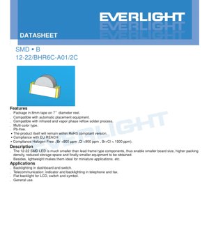
1. Product Overview
12-22 SMD LED wani ƙaramin na'ura ne mai haɗawa da saman, wanda aka ƙera don aikace-aikacen PCB masu yawan girma. Yana samuwa a cikin tsarin launuka da yawa, musamman yana haɗa LED shuɗi (guntun BH) da LED ja mai haske (guntun R6) a cikin fakit ɗaya. Wannan ɓangaren ya fi ƙanƙanta sosai idan aka kwatanta da LED na tsohuwar nau'in firam ɗin jagora, wanda ke ba da damar rage girman allon sosai, ƙara yawan tattarawa, rage buƙatun ajiya, kuma a ƙarshe yana ba da gudummawa ga haɓaka ƙananan kayan aikin mai amfani. Ginin sa mai sauƙi ya sa ya dace musamman don ƙananan aikace-aikace da waɗanda ke da ƙarancin sarari.
1.1 Core Advantages
- Miniaturization: The small footprint (1.2mm x 2.2mm) allows for high-density placement on PCBs.
- Compatibility: Packaged in 8mm tape on 7-inch diameter reels, making it fully compatible with standard automatic placement (pick-and-place) equipment.
- Robust Manufacturing: Compatible with both infrared (IR) and vapor phase reflow soldering processes.
- Environmental Compliance: The product is Pb-free, compliant with RoHS, EU REACH, and halogen-free standards (Br <900 ppm, Cl <900 ppm, Br+Cl < 1500 ppm).
1.2 Target Applications
- Automotive/Industrial: Backlighting for instrument panels, dashboards, and switches.
- Telecommunications: Status indicators and keypad backlighting in telephones and fax machines.
- Consumer Electronics: Flat backlighting for LCDs, switch illumination, and symbol lighting.
- General Purpose: Any application requiring a reliable, compact indicator light.
2. In-Depth Technical Parameter Analysis
The following sections provide a detailed breakdown of the device's electrical, optical, and thermal specifications. All parameters are measured at an ambient temperature (Ta) of 25°C unless otherwise specified.
2.1 Absolute Maximum Ratings
These ratings define the limits beyond which permanent damage to the device may occur. Operation under or at these conditions is not guaranteed.
| Parameter | Symbol | Code | Rating | Unit |
|---|---|---|---|---|
| Reverse Voltage | VR | - | 5 | V |
| Forward Current | IF | BH | 10 | mA |
| R6 | 25 | mA | ||
| Peak Forward Current (Duty 1/10 @1KHz) | IFP | BH | 40 | mA |
| R6 | 50 | mA | ||
| Power Dissipation | Pd | BH | 40 | mW |
| R6 | 60 | mW | ||
| Electrostatic Discharge (HBM) | ESD | BH | 150 | V |
| R6 | 2000 | V | ||
| Operating Temperature | Topr | - | -40 ~ +85 | °C |
| Storage Temperature | Tstg | - | -40 ~ +90 | °C |
| Soldering Temperature | Tsol | Reflow | 260°C for 10 sec. | - |
| Hand | 350°C for 3 sec. | - |
Key Observations: The red (R6) chip has a higher current and power handling capability compared to the blue (BH) chip. Notably, the ESD sensitivity differs significantly, with the BH (blue) chip being highly sensitive (150V HBM), requiring stringent ESD protection during handling, while the R6 (red) chip is more robust (2000V HBM).
2.2 Electro-Optical Characteristics
These are the typical performance parameters under normal operating conditions.
| Parameter | Symbol | Code | Min. | Typ. | Max. | Unit | Condition |
|---|---|---|---|---|---|---|---|
| Luminous Intensity | Iv | BH | 18.0 | 26.0 | ----- | mcd | IF=5mA |
| R6 | 22.5 | 30.0 | ----- | mcd | IF=5mA | ||
| Viewing Angle (2θ1/2) | - | - | ----- | 120 | ----- | deg | - |
| Peak Wavelength | λp | BH | ----- | 468 | ----- | nm | - |
| R6 | ----- | 632 | ----- | nm | - | ||
| Dominant Wavelength | λd | BH | ----- | 470 | ----- | nm | - |
| R6 | ----- | 624 | ----- | nm | - | ||
| Spectrum Bandwidth (Δλ) | - | BH | ----- | 25 | ----- | nm | - |
| R6 | ----- | 20 | ----- | nm | - | ||
| Forward Voltage | VF | BH | 2.7 | ----- | 3.1 | V | - |
| R6 | 1.7 | ----- | 2.2 | V | - | ||
| Reverse Current | IR | BH | ----- | ----- | 50 | μA | VR=5V |
| R6 | ----- | ----- | 10 | μA | VR=5V |
Notes:
- Tolerance of Luminous Intensity is ±11%.
- Tolerance of Forward Voltage is ±0.05V.
Analysis: LED bulu (BH) yana aiki a mafi girma na gaba wutar lantarki (2.7-3.1V) na yau da kullun na InGaN-based guntu, yayin da ja LED (R6) yana da ƙarancin wutar lantarki (1.7-2.2V) halayyar AlGaInP fasaha. Hasken haske an ƙayyade shi a ƙananan kuzarin tuƙi na 5mA, yana nuna ingantaccen aiki. Faɗin kusurwar kallo na digiri 120 yana ba da tsarin fitarwa mai faɗi wanda ya dace da aikace-aikacen nuna alama.
3. Performance Curve Analysis
Takardar bayanai tana ba da madaidaicin halayen lanƙwasa na duka BH (Bulu) da R6 (Ja) guntu, waɗanda ke da mahimmanci don fahimtar halayyar na'ura a ƙarƙashin yanayi daban-daban.
3.1 Relative Luminous Intensity vs. Ambient Temperature
The curves show that luminous output decreases as ambient temperature increases. This thermal quenching effect is a fundamental property of LED semiconductors. Designers must account for this derating when operating at high ambient temperatures to ensure sufficient light output.
3.2 Relative Luminous Intensity vs. Forward Current
These plots illustrate the sub-linear relationship between drive current and light output. Increasing current yields diminishing returns in brightness while generating more heat. Operating near the absolute maximum current rating is inefficient and reduces device lifetime.
3.3 Forward Current Derating Curve
This critical graph defines the maximum allowable continuous forward current as a function of ambient temperature. As temperature rises, the maximum permissible current must be reduced to prevent exceeding the device's power dissipation limit and causing thermal runaway.
3.4 Forward Voltage vs. Forward Current (I-V Curve)
The I-V curve shows the exponential relationship typical of a diode. The "knee" voltage is the approximate forward voltage (VF). The curve's slope in the conducting region relates to the dynamic resistance of the LED.
3.5 Radiation Diagram
The polar plot visualizes the spatial distribution of light intensity, confirming the 120-degree viewing angle. The pattern is typically Lambertian or near-Lambertian for this type of LED package.
3.6 Spectrum Distribution
The spectral plots show the emission profiles:
- BH (Blue): Peak wavelength ~468nm, dominant wavelength ~470nm, with a spectral bandwidth (FWHM) of ~25nm.
- R6 (Red): Peak wavelength ~632nm, dominant wavelength ~624nm, with a narrower spectral bandwidth of ~20nm.
4. Mechanical and Package Information
4.1 Package Dimensions
The 12-22 SMD LED has a compact rectangular package. Key dimensions (in mm, tolerance ±0.1mm unless specified) include:
- Overall length: 2.2 mm
- Overall width: 1.2 mm
- Overall height: 1.1 mm
- Lead (terminal) dimensions and spacing as per the detailed drawing.
4.2 Polarity Identification
The component features a polarity marker, typically a notch or a dot on the package or a cut corner on the carrier tape pocket, to indicate the cathode. Correct orientation is essential for circuit operation.
5. Soldering and Assembly Guidelines
Proper handling is critical for reliability. The device is moisture-sensitive (MSL) and requires specific soldering profiles.
5.1 Storage and Moisture Sensitivity
- Before Opening: Ajiya a ≤30°C da ≤90% RH.
- Bayan Budewa (Rayuwar Benen): Shekara 1 a ≤30°C da ≤60% RH. Dole ne a sake rufe sassan da ba a yi amfani da su ba a cikin marufi mai hana danshi tare da desiccant.
- Baking: If the desiccant indicates moisture absorption or storage time is exceeded, bake at 60 ±5°C for 24 hours before use.
5.2 Reflow Soldering Profile (Pb-free)
The recommended profile is for lead-free solder (e.g., SAC305):
- Preheat: Gradual ramp to activate flux.
- Soak Zone: To evenly heat the board and component.
- Reflow: Peak temperature of 260°C for a maximum of 10 seconds.
- Cooling: Controlled cool-down to minimize thermal stress.
5.3 Hand Soldering
If manual soldering is unavoidable:
- Use a soldering iron with a tip temperature <350°C.
- Limit contact time to ≤3 seconds per terminal.
- Use an iron with power ≤25W.
- Allow ≥2 seconds between soldering each terminal to avoid overheating.
- Hand soldering carries a higher risk of damage.
5.4 Rework and Repair
Repair after soldering is strongly discouraged. If absolutely necessary:
- Use a specialized double-head soldering iron designed for SMD removal to apply simultaneous, balanced heat to both terminals.
- Always verify that the repair process does not degrade the LED's characteristics.
6. Packaging and Ordering Information
6.1 Standard Packaging
LEDs are supplied in moisture-resistant packaging:
- Carrier Tape: 8mm wide tape.
- Reel: 7-inch (178mm) diameter.
- Quantity: 2000 pieces per reel.
- The packaging includes a desiccant and is sealed in an aluminum moisture-proof bag.
6.2 Label Explanation
The reel label contains several codes:
- CPN: Customer's Product Number.
- P/N: Product Number (e.g., 12-22/BHR6C-A01/2C).
- QTY: Packing Quantity.
- CAT: Luminous Intensity Rank.
- HUE: Chromaticity Coordinates & Dominant Wavelength Rank.
- REF: Forward Voltage Rank.
- LOT No: Manufacturing Lot Number for traceability.
7. Application Design Considerations
7.1 Current Limiting is Mandatory
LEDs are current-driven devices. An external current-limiting resistor (or constant current driver) is absolutely required for each chip (BH and R6). The forward voltage (VF) has a tolerance and a negative temperature coefficient (decreases as temperature rises). Connecting an LED directly to a voltage source, even one close to its nominal VF, can cause a small voltage increase to drive a large, uncontrolled current surge, leading to instantaneous failure (burn-out). The resistor value is calculated using Ohm's Law: R = (Vsupply - VF) / IF.
7.2 Thermal Management
Ko package ya yi ƙanƙanta, ɓarnawar wutar lantarki (40mW don BH, 60mW don R6) tana haifar da zafi. Don aiki mai dogon lokaci da ya dace:
- Ku bi daidai da lanƙwasar lanƙwasa na halin yanzu na gaba a yanayin yanayi mai girma.
- Ensure adequate PCB copper area (thermal relief pads) to conduct heat away from the LED solder joints.
- Avoid placing the LED near other heat-generating components.
7.3 ESD Protection
Chip ya buluu (BH) ni nyeti sana kwa ESD (150V HBM). Tekeleza ulinzi wa ESD katika mchakato mzima wa uzalishaji:
- Tumia vituo vya kazi vilivyogunduliwa na vifungo vya mkono wakati wa kushughulikia na kukusanyika.
- Fikiria kuongeza diode za kukandamiza voltage za muda mfupi (TVS) au saketi nyingine za ulinzi kwenye PCB ikiwa LED imeunganishwa na interfaces za nje zinazoweza kupata matukio ya ESD.
8. Technical Comparison and Positioning
The 12-22/BHR6C-A01/2C offers a specific combination of features:
- vs. Larger SMD LEDs (e.g., 3528, 5050): It provides a much smaller footprint for ultra-compact designs but with correspondingly lower maximum light output and power handling.
- vs. Single-Color 12-22 LEDs: The multi-color (blue+red) configuration in one package saves board space compared to using two separate single-color LEDs, simplifying assembly and inventory.
- vs. Leaded LEDs: It eliminates the need for through-holes, enables automated assembly, and reduces overall product size and weight.
9. Frequently Asked Questions (FAQs)
9.1 Ina iya tuƙa guntu na shuɗi da ja tare daga tushen wutar lantarki ɗaya?
Not directly in a simple series or parallel configuration due to their different forward voltages (VF). The blue chip requires ~3V, while the red chip requires ~2V. If connected in parallel to a 3V source, the red chip would experience excessive current. If connected in series, a 5V+ source would be needed, and current matching would be poor. The recommended approach is to use separate current-limiting resistors for each chip, even if they share a common voltage rail, or to drive them independently.
9.2 Me ya sa ƙimar ESD ta bambanta sosai tsakanin guntu na shuɗi da ja?
Wannan ya samo asali ne daga bambance-bambance na asali a fasahar kayan semiconductor. LED shuɗin yana amfani da tsarin InGaN (Indium Gallium Nitride) da aka girma akan abubuwan kamar sapphire ko silicon carbide, wanda zai iya zama mafi saukin lalacewa ta hanyar fitar da wutar lantarki a matakin haɗin microscopic. LED ja yana amfani da tsarin AlGaInP (Aluminum Gallium Indium Phosphide), wanda a asalinsa ya fi ƙarfi a kan ESD. Wannan yana buƙatar ƙarin kulawa lokacin sarrafa kayan shuɗi.
9.3 What does the "A01/2C" in the part number signify?
While the full internal coding isn't detailed in this excerpt, suffixes like these typically denote specific bins for key parameters such as luminous intensity (CAT), dominant wavelength/chromaticity (HUE), and forward voltage (REF). "A01" and "2C" likely specify the exact performance bins for the blue and red chips, respectively, ensuring color and brightness consistency within a production run.
10. Practical Design Example
Scenario: Design a bi-color status indicator using the 12-22/BHR6C-A01/2C. The LED will be powered from a 5V microcontroller GPIO pin. The goal is to drive each chip at approximately 5mA.
Calculation for Current-Limiting Resistors:
- For Blue Chip (BH, VF ≈ 2.9V typ): Rblue = (5V - 2.9V) / 0.005A = 420 Ω. Use a standard 430 Ω resistor. Power dissipation in resistor: P = I2R = (0.005)2 * 430 = 0.01075W (a 1/10W or 1/8W resistor is sufficient).
- For Red Chip (R6, VF ≈ 1.95V typ): Rred = (5V - 1.95V) / 0.005A = 610 Ω. Use a standard 620 Ω resistor. Power dissipation: (0.005)2 * 620 = 0.0155W.
11. Operating Principle
Light Emitting Diodes (LEDs) na'urori ne na semiconductor p-n junction. Lokacin da ake amfani da ƙarfin lantarki na gaba wanda ya wuce ƙarfin da aka gina a cikin junction, electrons daga yankin n-type suna haɗuwa da ramuka daga yankin p-type a cikin Layer mai aiki. Wannan tsarin haɗuwa yana sakin makamashi a cikin nau'in photons (haske). Takamaiman tsayin raƙuman ruwa (launi) na hasken da aka fitar an ƙaddara shi ta hanyar makamashin bandgap na kayan semiconductor da aka yi amfani da su a yankin mai aiki. LED shuɗi (BH) yana amfani da wani fili na InGaN, wanda ke da babban bandgap, yana fitar da mafi girman makamashin photons a cikin bakan shuɗi. LED ja (R6) yana amfani da wani fili na AlGaInP, wanda ke da ƙaramin bandgap, yana fitar da ƙananan makamashin photons a cikin bakan ja. Ruwan tabarau na epoxy yana siffanta fitarwar haske kuma yana ba da kariya ta injiniya da muhalli.
Istilahi ya Uainishaji wa LED
Maelezo kamili ya istilahi za kiufundi za LED
Utendaji wa Photoelectric
| Term | Unit/Representation | Simple Explanation | Why Important |
|---|---|---|---|
| Luminous Efficacy | lm/W (lumens per watt) | Light output per watt of electricity, higher means more energy efficient. | Directly determines energy efficiency grade and electricity cost. |
| Luminous Flux | lm (lumens) | Total light emitted by source, commonly called "brightness". | Determines if the light is bright enough. |
| Kwanin Duba | ° (digiri), misali, 120° | Kwanin da ƙarfin haske ya ragu zuwa rabi, yana ƙayyade faɗin katako. | Affects illumination range and uniformity. |
| CCT (Color Temperature) | K (Kelvin), misal, 2700K/6500K | Gumi/ƙanƙanta na haske, ƙananan ƙimomi suna rawaya/dumi, mafi girma fari/sanyi. | Yana ƙayyade yanayin hasken da ya dace da yanayin da ya dace. |
| CRI / Ra | Unitless, 0–100 | Ability to render object colors accurately, Ra≥80 is good. | Affects color authenticity, used in high-demand places like malls, museums. |
| SDCM | MacAdam ellipse steps, e.g., "5-step" | Color consistency metric, smaller steps mean more consistent color. | Ensures uniform color across same batch of LEDs. |
| Dominant Wavelength | nm (nanometers), e.g., 620nm (red) | Wavelength corresponding to color of colored LEDs. | Determines hue of red, yellow, green monochrome LEDs. |
| Spectral Distribution | Wavelength vs intensity curve | Shows intensity distribution across wavelengths. | Affects color rendering and quality. |
Electrical Parameters
| Term | Symbol | Simple Explanation | Design Considerations |
|---|---|---|---|
| Forward Voltage | Vf | Minimum voltage to turn on LED, like "starting threshold". | Driver voltage must be ≥Vf, voltages add up for series LEDs. |
| Forward Current | If | Current value for normal LED operation. | Usually constant current drive, current determines brightness & lifespan. |
| Max Pulse Current | Ifp | Peak current tolerable for short periods, used for dimming or flashing. | Pulse width & duty cycle must be strictly controlled to avoid damage. |
| Reverse Voltage | Vr | Max reverse voltage LED can withstand, beyond may cause breakdown. | Circuit must prevent reverse connection or voltage spikes. |
| Thermal Resistance | Rth (°C/W) | Resistance to heat transfer from chip to solder, lower is better. | High thermal resistance requires stronger heat dissipation. |
| ESD Immunity | V (HBM), e.g., 1000V | Ability to withstand electrostatic discharge, higher means less vulnerable. | Anti-static measures needed in production, especially for sensitive LEDs. |
Thermal Management & Reliability
| Term | Key Metric | Simple Explanation | Impact |
|---|---|---|---|
| Junction Temperature | Tj (°C) | Actual operating temperature inside LED chip. | Every 10°C reduction may double lifespan; too high causes light decay, color shift. |
| Kupungua kwa Lumen | L70 / L80 (masaa) | Time for brightness to drop to 70% or 80% of initial. | Directly defines LED "service life". |
| Lumen Maintenance | % (e.g., 70%) | Percentage of brightness retained after time. | Indicates brightness retention over long-term use. |
| Color Shift | Δu′v′ or MacAdam ellipse | Degree of color change during use. | Affects color consistency in lighting scenes. |
| Thermal Aging | Material degradation | Deterioration due to long-term high temperature. | May cause brightness drop, color change, or open-circuit failure. |
Packaging & Materials
| Term | Common Types | Simple Explanation | Features & Applications |
|---|---|---|---|
| Package Type | EMC, PPA, Ceramic | Housing material protecting chip, providing optical/thermal interface. | EMC: good heat resistance, low cost; Ceramic: better heat dissipation, longer life. |
| Chip Structure | Front, Flip Chip | Chip electrode arrangement. | Flip chip: better heat dissipation, higher efficacy, for high-power. |
| Phosphor Coating | YAG, Silicate, Nitride | Covers blue chip, converts some to yellow/red, mixes to white. | Different phosphors affect efficacy, CCT, and CRI. |
| Lens/Optics | Flat, Microlens, TIR | Optical structure on surface controlling light distribution. | Determines viewing angle and light distribution curve. |
Quality Control & Binning
| Term | Binning Content | Simple Explanation | Purpose |
|---|---|---|---|
| Luminous Flux Bin | Code e.g., 2G, 2H | Grouped by brightness, each group has min/max lumen values. | Ensures uniform brightness in same batch. |
| Voltage Bin | Code e.g., 6W, 6X | An rarrabe ta hanyar kewayon ƙarfin lantarki na gaba. | Facilitates driver matching, improves system efficiency. |
| Color Bin | 5-step MacAdam ellipse | An rarraba ta hanyar daidaitawar launi, tabbatar da ƙuntataccen kewayon. | Yana ba da tabbacin daidaiton launi, yana guje wa rashin daidaiton launi a cikin kayan haske. |
| CCT Bin | 2700K, 3000K etc. | Grouped by CCT, each has corresponding coordinate range. | Meets different scene CCT requirements. |
Testing & Certification
| Term | Standard/Test | Simple Explanation | Significance |
|---|---|---|---|
| LM-80 | Lumen maintenance test | Long-term lighting at constant temperature, recording brightness decay. | Used to estimate LED life (with TM-21). |
| TM-21 | Standard ya kukadiria maisha | Inakadiria maisha chini ya hali halisi kulingana na data ya LM-80. | Inatoa utabiri wa kisayansi wa maisha. |
| IESNA | Illuminating Engineering Society | Covers optical, electrical, thermal test methods. | Industry-recognized test basis. |
| RoHS / REACH | Takardun muhalli | Yana tabbatar da babu abubuwa masu cutarwa (gubar, mercury). | Market access requirement internationally. |
| ENERGY STAR / DLC | Energy efficiency certification | Energy efficiency and performance certification for lighting. | Used in government procurement, subsidy programs, enhances competitiveness. |