Table of Contents
- 1. Product Overview
- 2. Detailed Technical Specifications
- 2.1 Absolute Maximum Ratings
- 2.2 Electro-Optical Characteristics
- 3. Grading System Description
- 3.1 Luminous Intensity Binning
- 3.2 Dominant Wavelength Binning
- 3.3 Forward Voltage Binning
- 4. Performance Curve Analysis
- 4.1 Luminous Intensity vs. Forward Current
- 4.2 Luminous Intensity vs. Ambient Temperature
- 4.3 Forward Current Derating Curve
- 4.4 Spectral Distribution
- 4.5 Forward Voltage vs. Forward Current
- 4.6 Radiation Pattern
- 5. Mechanical and Packaging Information
- 5.1 Package Dimensions
- 5.2 Polarity Marking
- 6. Soldering and Assembly Guide
- 6.1 Overcurrent Protection
- 6.2 Storage and Moisture Sensitivity
- 6.3 Reflow Soldering Temperature Profile
- 6.4 Manual soldering and rework
- 7. Packaging and ordering information
- 7.1 Reel and Carrier Tape Specifications
- 7.2 Label Description
- 8. Application Suggestions
- 8.1 Typical Application Scenarios
- 8.2 Design Considerations
- 9. Technical Comparison and Differentiation
- 10. Frequently Asked Questions (Based on Technical Specifications)
- 10.1 When using a 5V power supply, what resistance value should be selected?
- 10.2 Can I drive this LED with 30mA to achieve higher brightness?
- 10.3 Why is there a 7-day usage limit after opening the moisture barrier bag?
- 10.4 What does the binning code "R6C-AP1Q2L/3T" in the part number represent?
- 11. Practical Design and Usage Cases
- 12. Introduction to Technical Principles
- 13. Industry Trends and Development
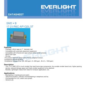
1. Product Overview
17-21/R6C-AP1Q2L/3T is a surface-mount device (SMD) LED that utilizes AIGaInP semiconductor technology to emit bright red light. This component is specifically designed for high-density PCB applications where space and weight are critical constraints. Its primary advantages include a significantly reduced footprint compared to lead-frame type LEDs, enabling more compact board designs, higher packaging density, and ultimately smaller end-user devices. Its lightweight construction makes it particularly suitable for miniature and portable electronic equipment.
该 LED 以 8mm 载带包装,卷绕在直径为 7 英寸的卷盘上,完全兼容标准自动化贴片组装设备。其配方为无铅,并符合包括 RoHS、欧盟 REACH 和无卤标准(Br <900 ppm,Cl <900 ppm,Br+Cl < 1500 ppm)在内的主要环保法规。该器件兼容红外和气相回流焊接工艺。
2. Detailed Technical Specifications
2.1 Absolute Maximum Ratings
The device is rated to operate under the following absolute maximum conditions. Exceeding these conditions may cause permanent damage. All ratings are specified at an ambient temperature (Ta) of 25°C.
- Reverse Voltage (VR):5 V. Exceeding this voltage under reverse bias may cause junction breakdown.
- Continuous Forward Current (IF):25 mA. This is the maximum DC current for reliable operation.
- Peak Forward Current (IFP):60 mA. This rating applies under pulse conditions with a duty cycle of 1/10 and a frequency of 1 kHz.
- Power Dissipation (Pd):60 mW. This is the maximum power that the package can dissipate.
- Electrostatic Discharge (ESD) Human Body Model (HBM):2000 V. ESD handling procedures must be followed during assembly.
- Operating temperature range (Topr):-40°C to +85°C.
- Storage temperature range (Tstg):-40°C to +90°C.
- Soldering Temperature (Tsol):This device can withstand reflow soldering with a peak temperature of 260°C for 10 seconds, or hand soldering at 350°C per pin for 3 seconds.
2.2 Electro-Optical Characteristics
Key performance parameters are measured at Ta=25°C and standard test current IF=20 mA. These parameters define the core light output and electrical behavior of the LED.
- Luminous Intensity (Iv):Range from minimum 45.0 mcd to maximum 112.0 mcd. Typical value falls within this range according to specific binning code.
- Viewing Angle (2θ1/2):Typical wide viewing angle is 140 degrees, providing broad and uniform illumination.
- Peak Wavelength (λp):The typical value is 632 nm, representing the wavelength at which the spectral power distribution is highest.
- Dominant Wavelength (λd):The range is from 617.5 nm to 633.5 nm. This is the single wavelength at which the human eye perceives the LED color and is a key parameter for color consistency.
- Spectral Bandwidth (Δλ):The typical value is 20 nm, defining the spectral purity of the emitted red light.
- Forward Voltage (VF):At IF=20mA, the range is from 1.7 V to 2.3 V. This parameter is crucial for circuit design and current-limiting resistor calculation.
- Reverse Current (IR):When a 5V reverse voltage is applied, the maximum is 10 μA. This device is not designed for reverse bias operation.
Important Note:Tolerance is specified as: Luminous Intensity ±11%, Dominant Wavelength ±1nm, Forward Voltage ±0.05V. Reverse voltage condition is for IR test only; LED should not be operated under reverse bias.
3. Grading System Description
Kada ake tabbatar da daidaiton aiki a cikin samarwa, ana rarraba LED zuwa matakai daban-daban bisa ga ma'auni masu mahimmanci. Wannan yana ba masu zane damar zaɓar na'urorin da suka dace da buƙatun haske da launi na takamaiman aikace-aikace.
3.1 Luminous Intensity Binning
Ana rarraba a cikin IF=20mA. Lambobin rarrabuwa (misali P1, Q2) suna ayyana mafi ƙarancin da mafi girman ƙarfin haskakawa.
- P1:45.0 - 57.0 mcd
- P2:57.0 - 72.0 mcd
- Q1:72.0 - 90.0 mcd
- Q2:90.0 - 112.0 mcd
3.2 Dominant Wavelength Binning
Binning at IF=20mA. The binning code (E4-E7) defines the chromaticity coordinates for red emission.
- E4:617.5 - 621.5 nm
- E5:621.5 - 625.5 nm
- E6:625.5 - 629.5 nm
- E7:629.5 - 633.5 nm
3.3 Forward Voltage Binning
Binning at IF=20mA. The binning code (19-24) defines the electrical characteristics required for power supply design.
- 19:1.7 - 1.8 V
- 20:1.8 - 1.9 V
- 21:1.9 - 2.0 V
- 22:2.0 - 2.1 V
- 23:2.1 - 2.2 V
- 24:2.2 - 2.3 V
4. Performance Curve Analysis
The datasheet provides several characteristic curves that illustrate the device's behavior under different conditions. These are crucial for robust system design.
4.1 Luminous Intensity vs. Forward Current
This curve shows a roughly linear relationship between forward current (IF) and relative luminous intensity up to the maximum rated current. It confirms that within the operating range, the light output is proportional to the drive current.
4.2 Luminous Intensity vs. Ambient Temperature
This curve illustrates the temperature dependence of light output. Luminous intensity typically decreases as the ambient temperature (Ta) increases, especially above room temperature. This derating must be considered in applications with high ambient temperatures or poor thermal management.
4.3 Forward Current Derating Curve
This graph defines the functional relationship between the maximum allowable continuous forward current and the ambient temperature. As the temperature increases, the maximum allowable current must be reduced to stay within the device's power dissipation limits, prevent thermal runaway, and ensure long-term reliability.
4.4 Spectral Distribution
The spectral output curve shows a narrow single peak centered at 632 nm, characteristic of AIGaInP-based red LEDs. The typical 20 nm bandwidth indicates good color saturation.
4.5 Forward Voltage vs. Forward Current
This IV curve shows the typical exponential relationship of a diode. The forward voltage increases with current, and its value at 20mA is a key parameter for binning and circuit design.
4.6 Radiation Pattern
The polar plot illustrates the spatial distribution of light intensity, confirming a wide viewing angle of 140 degrees. The light intensity is highest at 0 degrees (perpendicular to the LED surface) and decreases towards the edges.
5. Mechanical and Packaging Information
5.1 Package Dimensions
The 17-21 SMD LED uses a compact rectangular package. Key dimensions (unit: mm, tolerance ±0.1mm unless otherwise specified) include: body length 1.6 mm, width 0.8 mm, height 0.6 mm. The datasheet provides a detailed drawing showing all key dimensions, including pad pitch and pad recommendations.
5.2 Polarity Marking
The cathode is clearly marked on the package. During PCB layout and assembly, the correct polarity orientation is crucial to ensure proper operation. The diagram in the datasheet indicates the position of this mark relative to the package geometry.
6. Soldering and Assembly Guide
6.1 Overcurrent Protection
An external current limiting resistor must be used. The forward voltage has a negative temperature coefficient, which means that as the junction temperature increases, VF decreases. If driven by a constant voltage source, this can lead to a sharp increase in current. This can cause thermal runaway and device failure. A series resistor provides linear, stable current drive.
6.2 Storage and Moisture Sensitivity
LEDs are packed in moisture barrier bags with desiccant to prevent moisture absorption, which can cause "popcorn" phenomenon (package cracking) during reflow soldering.
- Do not open the bag before use.
- After opening, use within 168 hours (7 days) if stored at ≤30°C and ≤60% RH.
- If not used within this period, or if the desiccant indicator shows saturation, the component must be baked at 60 ±5°C for 24 hours before use.
6.3 Reflow Soldering Temperature Profile
Specified the lead-free reflow soldering temperature profile:
- Preheating:150-200°C, for 60-120 seconds.
- Time Above Liquidus (TAL):Above 217°C, for 60-150 seconds.
- Peak Temperature:Maximum 260°C, hold time up to 10 seconds.
- Heating Rate:Maximum 6°C/s up to 255°C, then maximum 3°C/s up to the peak temperature.
- Reflow soldering should not exceed two times.
- Avoid applying mechanical stress to the package during heating and cooling.
6.4 Manual soldering and rework
如果必须进行手工焊接,请使用烙铁头温度 <350°C 的烙铁,对每个引脚加热 <3 秒,并使用功率 <25W 的烙铁。焊接每个引脚之间至少间隔 2 秒。强烈不建议在初次焊接后进行返修。如果绝对不可避免,请使用双头烙铁同时加热两个引脚并取下元件,以避免对焊点施加应力。在任何返修尝试后,务必验证器件功能。
7. Packaging and ordering information
7.1 Reel and Carrier Tape Specifications
Components are supplied in embossed carrier tape on 7-inch diameter reels. The carrier tape width is 8 mm. Each reel contains 3000 components. Detailed drawings of reel dimensions, carrier tape pocket dimensions, and cover tape specifications are provided to ensure compatibility with automated assembly equipment.
7.2 Label Description
The reel label contains several key identifiers:
- CPN:Customer Part Number (optional).
- P/N:Manufacturer's full part number (e.g., 17-21/R6C-AP1Q2L/3T).
- QTY:QTY per roll (3000 pcs).
- CAT:Luminous intensity bin grade (e.g., Q2).
- HUE:Chromaticity/Dominant wavelength bin grade (e.g., E6).
- REF:Forward voltage bin grade (e.g., 21).
- LOT No:Traceable production lot number.
8. Application Suggestions
8.1 Typical Application Scenarios
- Backlight Illumination:Due to its small size and uniform viewing angle, it is very suitable for dashboard indicator lights, switch illumination, and symbol backlighting.
- Communication Equipment:Status indicator lights and keyboard backlighting in telephones, fax machines, and other communication equipment.
- LCD Flat Backlight:Can be used in arrays for small, thin LCD displays.
- General Indicator Light:Widely used in consumer and industrial electronic products for power status, mode indication, and alarm signals.
8.2 Design Considerations
- Current Drive:Always use a constant current source or a voltage source with a series resistor. Calculate the resistor value using the formula R = (Vsupply - VF) / IF, using the maximum VF from the binning or datasheet to ensure the current does not exceed 20mA (or the selected operating point) under worst-case conditions.
- Thermal Management:Although the package is small, ensure sufficient PCB copper area or thermal vias to keep the junction temperature within limits when operating at high ambient temperatures or near the maximum current.
- Optical Design:The 140-degree wide viewing angle provides broad illumination. For focused light, external lenses or light guides may be required.
- ESD Protection:Implement standard ESD precautions during operation and assembly. If the LED is connected to a user-accessible port, consider adding a transient voltage suppressor on the input line.
9. Technical Comparison and Differentiation
17-21 package has significant advantages in the indicator LED field.
- Compared with leaded LEDs (e.g., 3mm, 5mm):The main advantages are a significantly reduced board footprint and height, enabling a modern, miniaturized design. It also eliminates the steps of manual insertion and cutting/bending leads, simplifying automated assembly.
- Compared to other SMD LEDs (e.g., 0402, 0603):The 17-21 package (1.6x0.8mm) is slightly larger than the smallest chip LEDs, making it easier to handle and solder manually when needed, while still being very compact. It may also offer higher light output due to the potential for larger chip sizes within the package.
- Material Technology (AIGaInP):Compared to older technologies such as GaAsP, AIGaInP provides higher efficiency, brighter output, and better color purity (saturated red) at the same input current.
10. Frequently Asked Questions (Based on Technical Specifications)
10.1 When using a 5V power supply, what resistance value should be selected?
Using a maximum VF of 2.3V (from the 24th bin) and a safe target IF of 20mA: R = (5V - 2.3V) / 0.020A = 135 ohms. The closest standard values are 130 or 150 ohms. The resistor's power rating should be at least P = I^2 * R = (0.02^2)*150 = 0.06W, so a 1/8W (0.125W) resistor is sufficient.
10.2 Can I drive this LED with 30mA to achieve higher brightness?
A'a. Matsakaicin ƙayyadaddun ƙimar halin yanzu na ci gaba shine 25 mA. Yin aiki da 30 mA ya wuce wannan ƙimar, wannan zai rage amincin, hanzarta raguwar haske, kuma yana iya haifar da gazawar nan take. Idan ana buƙatar haske mafi girma, zaɓi LED daga matakin ƙarfin haske mafi girma (misali Q2), ko jerin samfuran da ke da ƙimar halin yanzu mafi girma.
10.3 Why is there a 7-day usage limit after opening the moisture barrier bag?
Plastic packaging materials absorb moisture from the air. During high-temperature reflow soldering, this absorbed moisture rapidly turns into steam, creating internal pressure that can lead to package delamination or epoxy lens cracking (the "popcorn" phenomenon). The 7-day period under controlled humidity ensures moisture absorption remains below the critical level.
10.4 What does the binning code "R6C-AP1Q2L/3T" in the part number represent?
While the full decoding may be proprietary, it typically encodes the product family (17-21), color (R for red, 6C likely specifies a particular chromaticity), and performance bins for intensity, wavelength, and voltage (implied by elements like Q2). "3T" may refer to tape-and-reel packaging. For exact binning information, refer to the CAT, HUE, and REF codes on the reel label.
11. Practical Design and Usage Cases
Scenario: Designing a multi-indicator status panel for a portable medical device.
The device requires the placement of 5 independent red status LEDs (low battery, charging, error, mode 1, mode 2) on a highly integrated PCB. Space is extremely limited, and the device must be lightweight.
Solution Implementation:
- Component Selection:Select the 17-21/R6C-AP1Q2L/3T LED for its ultra-compact 1.6x0.8mm footprint, which saves valuable board space compared to larger alternatives.
- Circuit Design:The system microcontroller operates at 3.3V. Using a typical VF of 2.0V (21 grades) and a design IF of 15mA to ensure long life and account for minor temperature variations: R = (3.3V - 2.0V) / 0.015A = 86.7 ohms. A 1% 82-ohm resistor is selected, resulting in a slightly higher IF of approximately ~16mA, which is well within the 25mA limit.
- PCB Layout:LEDs are placed with a 3.0mm center-to-center pitch for clear visual distinction. The cathode pad is connected to the microcontroller GPIO pin (configured as open-drain output) to switch the LED. The anode pad is connected to 3.3V via a current-limiting resistor. A small keep-out area is maintained beneath the LED to prevent solder wicking.
- Assembly:LED supplied on 8mm carrier tape reels, compatible with pick-and-place machines. Program the lead-free reflow temperature profile from Section 6.3 into the reflow oven. The factory floor follows humidity control procedures; reels opened for sample inspection more than 7 days before a production run are baked.
- Results:A cimma a yanki mafi ƙanƙanta, an samar da saitin fitilun jihohi masu dogaro, masu haske, kuma masu daidaito, wanda ya ba da gudummawa ga gabaɗaya ƙaramin girman na'urar likita ta ƙarshe da amincinta.
12. Introduction to Technical Principles
Wannan LED ya dogara ne akan kayan semiconductor na aluminum-indium-gallium-phosphide (AIGaInP) da ke girma akan substrate. Lokacin da aka yi amfani da ƙarfin lantarki mai kyau akan mahaɗin p-n, electrons daga yankin n-type da ramuka daga yankin p-type ana shigar da su cikin yanki mai aiki. Lokacin da waɗannan masu ɗaukar kaya suka haɗu, suna sakin makamashi a cikin nau'in photon (haske). Takamaiman tsawon raƙuman hasken da aka fitar—a cikin wannan misali, ja mai haske mai kusan 632 nm—ana ƙaddara shi ta hanyar makamashin tazarar band na abun da ke cikin gawa na AIGaInP. Ta hanyar sarrafa daidai gwargwado na aluminum, indium, gallium, da phosphorus yayin girma crystal, masana'antun na iya daidaita tazarar band, don samar da takamaiman launuka a cikin bakan ja, orange, da rawaya tare da ingantacciyar inganci da tsaftar launi mai girma. Kayan rufi na epoxy ana amfani dashi don kare ƙwaƙƙwaran guntu na semiconductor, a matsayin ruwan tabarau don siffata fitarwar haske (don haka samar da kusurwar hangen nesa na digiri 140), da kuma samar da tsarin injiniya don walda.
13. Industry Trends and Development
The trend for indicator and backlight LEDs continues strongly towards miniaturization, increased efficiency, and higher reliability. Packages like 17-21 are part of this evolution, filling the gap between the smallest chip-scale packages and larger traditional SMDs. To meet the needs of applications requiring a uniform appearance (such as indicator arrays and backlight panels), tighter binning tolerances for color and luminous flux are receiving increasing emphasis. Furthermore, the pursuit of higher efficiency (more lumens per watt) is ongoing, driving material science to improve internal quantum efficiency and the package's light extraction efficiency. Integration is another trend, with multi-LED packages and LEDs with built-in ICs for control or protection becoming increasingly common, although discrete components like 17-21 remain crucial for flexible, cost-effective designs. Environmental compliance (RoHS, REACH, halogen-free) is now a standard requirement across the industry, as reflected in the component's specifications.
Detailed Explanation of LED Specification Terminology
Complete Interpretation of LED Technical Terminology
I. Core Indicators of Photoelectric Performance
| Terminology | Unit/Representation | Popular Explanation | Why It Matters |
|---|---|---|---|
| Luminous Efficacy | lm/W (lumens per watt) | The luminous flux emitted per watt of electrical power; higher values indicate greater energy efficiency. | It directly determines the energy efficiency rating of the luminaire and the electricity cost. |
| Luminous Flux | lm (lumen) | The total amount of light emitted by a light source, commonly known as "brightness". | Determines whether the luminaire is bright enough. |
| Viewing Angle | ° (degree), e.g., 120° | The angle at which luminous intensity drops to half, determining the beam width. | Affects the range and uniformity of illumination. |
| Color Temperature (CCT) | K (Kelvin), such as 2700K/6500K | Launin haske mai dumi ko sanyi, ƙananan ƙima sun karkata zuwa rawaya/dumi, manyan ƙima sun karkata zuwa fari/sanyi. | Yana ƙayyade yanayin hasken wuta da kuma yanayin da ya dace. |
| Color Rendering Index (CRI / Ra) | Unitless, 0–100 | The ability of a light source to reproduce the true colors of objects, with Ra≥80 being preferable. | Affects color fidelity, used in high-demand places such as shopping malls and art galleries. |
| Color tolerance (SDCM) | MacAdam ellipse steps, such as "5-step" | A quantitative indicator of color consistency; a smaller step number indicates better color consistency. | Ensure no color difference among luminaires from the same batch. |
| Dominant Wavelength | nm (nanometer), e.g., 620nm (red) | Wavelength values corresponding to the colors of colored LEDs. | Determines the hue of monochromatic LEDs such as red, yellow, and green. |
| Spectral Distribution | Wavelength vs. Intensity Curve | Shows the intensity distribution of light emitted by an LED at each wavelength. | Affects color rendering and color quality. |
II. Electrical Parameters
| Terminology | Symbols | Popular Explanation | Design Considerations |
|---|---|---|---|
| Forward Voltage (Forward Voltage) | Vf | The minimum voltage required to light up an LED, similar to a "starting threshold". | The driving power supply voltage must be ≥ Vf, and the voltages add up when multiple LEDs are connected in series. |
| Forward Current | If | The current value that makes the LED emit light normally. | Constant current drive is often used, as the current determines brightness and lifespan. |
| Maximum Pulse Current | Ifp | The peak current that can be withstood for a short period of time, used for dimming or flashing. | Pulse width and duty cycle must be strictly controlled to prevent overheating damage. |
| Reverse Voltage | Vr | Maximum reverse voltage that an LED can withstand; exceeding it may cause breakdown. | Reverse connection or voltage surges must be prevented in the circuit. |
| Thermal Resistance (Thermal Resistance) | Rth (°C/W) | The resistance to heat flow from the chip to the solder joint. A lower value indicates better heat dissipation. | High thermal resistance requires stronger heat dissipation design, otherwise junction temperature will rise. |
| Electrostatic Discharge Immunity (ESD Immunity) | V (HBM), such as 1000V | Electrostatic discharge immunity; a higher value indicates greater resistance to damage from static electricity. | Anti-static measures must be implemented during production, especially for high-sensitivity LEDs. |
III. Thermal Management and Reliability
| Terminology | Key Indicators | Popular Explanation | Impact |
|---|---|---|---|
| Junction Temperature | Tj (°C) | The actual operating temperature inside the LED chip. | For every 10°C reduction, the lifespan may double; excessively high temperatures lead to lumen depreciation and color shift. |
| Lumen Depreciation | L70 / L80 (hours) | The time required for the brightness to drop to 70% or 80% of its initial value. | Directly define the "useful life" of an LED. |
| Lumen Maintenance | % (e.g., 70%) | The percentage of remaining brightness after a period of use. | Characterizes the ability to maintain brightness after long-term use. |
| Color Shift | Δu′v′ or MacAdam ellipse | The degree of color change during use. | Affects the color consistency of the lighting scene. |
| Thermal Aging | Material performance degradation | Degradation of packaging materials due to long-term high temperature. | Zai iya haifar da raguwar haske, canjin launi ko gazawar bude hanya. |
IV. Kullewa da Kayan aiki
| Terminology | Nau'o'in gama gari | Popular Explanation | Characteristics and Applications |
|---|---|---|---|
| Package Types | EMC, PPA, Ceramic | The housing material that protects the chip and provides optical and thermal interfaces. | EMC offers good heat resistance and low cost; ceramic provides superior heat dissipation and long lifespan. |
| Chip Structure | Front-side, Flip Chip | Chip electrode arrangement method. | Flip-chip offers better heat dissipation and higher luminous efficacy, suitable for high-power applications. |
| Phosphor coating. | YAG, silicate, nitride | Coated on the blue LED chip, partially converted to yellow/red light, mixed to form white light. | Different phosphors affect luminous efficacy, color temperature, and color rendering. |
| Lens/Optical Design | Flat, microlens, total internal reflection | Optical structure on the packaging surface, controlling light distribution. | Determines the emission angle and light distribution curve. |
V. Quality Control and Grading
| Terminology | Grading Content | Popular Explanation | Purpose |
|---|---|---|---|
| Luminous Flux Binning | Codes such as 2G, 2H | Group by brightness level, each group has a minimum/maximum lumen value. | Ensure consistent brightness for products in the same batch. |
| Voltage binning | Codes such as 6W, 6X | Grouped by forward voltage range. | Ease of matching the driving power supply, improving system efficiency. |
| Color binning | 5-step MacAdam ellipse | Group by color coordinates to ensure colors fall within a minimal range. | Ensure color consistency to avoid uneven color within the same luminaire. |
| Color temperature grading | 2700K, 3000K, etc. | Group by color temperature, each group has a corresponding coordinate range. | Meet the color temperature requirements of different scenarios. |
VI. Testing and Certification
| Terminology | Standard/Test | Popular Explanation | Meaning |
|---|---|---|---|
| LM-80 | Lumen Maintenance Test | Long-term operation under constant temperature conditions, recording luminance attenuation data. | For estimating LED lifetime (in conjunction with TM-21). |
| TM-21 | Lifetime projection standard | Projecting lifespan under actual use conditions based on LM-80 data. | Providing scientific life prediction. |
| IESNA Standard | Illuminating Engineering Society Standard | Covers optical, electrical, and thermal test methods. | Industry-recognized testing basis. |
| RoHS / REACH | Environmental Certification | Ensure the product does not contain harmful substances (e.g., lead, mercury). | Entry requirements for the international market. |
| ENERGY STAR / DLC | Energy efficiency certification | Energy efficiency and performance certification for lighting products. | Commonly used in government procurement and subsidy programs to enhance market competitiveness. |