Table of Contents
- 1. Product Overview
- 2. Cikakken bayani na sigogi na fasaha
- 2.1 Absolute Maximum Ratings
- 2.2 Halayen haske da lantarki
- 3. Bayani na tsarin rarrabawa
- 3.1 Rarrabawar Ƙarfin Haskakawa
- 3.2 Rarrabawar Babban Tsawon Zango
- 3.3 Rarrabawar Ƙarfafawar Gaba
- 4. Bincike kan Lankwilar Aiki
- 4.1 Relative Luminous Intensity vs. Forward Current
- 4.2 Relative Luminous Intensity vs. Ambient Temperature
- 4.3 Forward Current Derating Curve
- 4.4 Forward Voltage vs. Forward Current
- 4.5 Radiation Pattern and Spectral Distribution
- 5. Mechanical and Packaging Information
- 5.1 Package Dimensions
- 5.2 Polarity Identification
- 6. Welding and Assembly Guide
- 6.1 Reflow Soldering Profile
- 6.2 Manual Soldering
- 6.3 Storage and Moisture Sensitivity
- 6.4 Key Considerations
- 7. Packaging and Ordering Information
- 7.1 Reel and Carrier Tape Specifications
- 7.2 Label Description
- 8. Application Recommendations
- 8.1 Typical Application Scenarios
- 8.2 Design Considerations
- 9. Technical Comparison and Differentiation
- 10. Frequently Asked Questions (Based on Technical Parameters)
- 10.1 When using a 5V power supply, what resistor value should I use?
- 10.2 Can I drive this LED with 30mA for higher brightness?
- 10.3 Why does the brightness decrease when the circuit board heats up?
- 10.4 Jakar an bude ta tun wata daya da suka wuce. Shin zan iya amfani da waɗannan LED ɗin?
- 11. Ƙira ta Ainihi da Misalan Amfani
- 12. Gabatarwa ga Ka'idoji
- 13. Hanyoyin Ci Gaba
- Detailed Explanation of LED Specification Terminology
- I. Core Indicators of Photoelectric Performance
- II. Electrical Parameters
- III. Thermal Management and Reliability
- IV. Packaging and Materials
- V. Quality Control and Binning
- VI. Testing and Certification
1. Product Overview
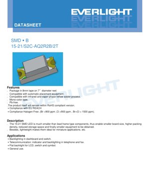
The 15-21/S2C-AQ2R2B/2T is a surface-mount device (SMD) LED utilizing AlGaInP (aluminum gallium indium phosphide) semiconductor technology, emitting bright orange light. This component is specifically designed for high-density PCB applications where space and weight are critical constraints. Compared to traditional lead-frame type LEDs, its compact form factor can significantly reduce board size and equipment volume.
该 LED 以 8mm 载带包装,卷绕在直径为 7 英寸的卷盘上,完全兼容自动化贴片组装设备。它是单色类型,符合无铅、RoHS、欧盟 REACH 和无卤素法规(Br <900 ppm,Cl <900 ppm,Br+Cl < 1500 ppm)。该器件适用于红外和气相回流焊接工艺。
2. Cikakken bayani na sigogi na fasaha
2.1 Absolute Maximum Ratings
These ratings define the limits beyond which permanent damage to the device may occur. Operation under these conditions is not guaranteed.
- Reverse Voltage (VR):5 V. Exceeding this voltage under reverse bias may cause junction breakdown.
- Continuous Forward Current (IF):25 mA. The maximum DC current for reliable operation.
- Peak Forward Current (IFP):60 mA. This is only permitted under pulse conditions with a duty cycle of 1/10 and a frequency of 1 kHz. It must not be used for continuous operation.
- Power Dissipation (Pd):60 mW. The maximum power that the package can dissipate at an ambient temperature (Ta) of 25°C. This value decreases with increasing temperature.
- Electrostatic Discharge (ESD) Human Body Model (HBM):2000 V. This indicates the device's sensitivity to static electricity. Proper ESD handling procedures must be followed.
- Operating Temperature (Topr):-40°C to +85°C. The specified ambient temperature range within which the device can operate.
- Storage Temperature (Tstg):-40°C to +90°C.
- Soldering Temperature:This device can withstand reflow soldering with a peak temperature of 260°C for up to 10 seconds, or hand soldering at 350°C per terminal for up to 3 seconds.
2.2 Halayen haske da lantarki
Unless otherwise specified, these parameters are measured under standard test conditions Ta=25°C and IF=20 mA. They define the optical and electrical performance of the LED.
- Luminous Intensity (Iv):Ranges from 90.0 mcd (minimum) to 180.0 mcd (maximum), with a typical tolerance of ±11%. This is the perceived brightness of the light source.
- Viewing Angle (2θ1/2):The typical value is 130 degrees. This is the full angle at which the luminous intensity is half of the intensity at 0 degrees (on-axis).
- Peak Wavelength (λp):The typical value is 611 nm. The wavelength at which the spectral power distribution reaches its maximum.
- Dominant Wavelength (λd):Ranges from 600.5 nm to 612.5 nm. This is the single wavelength that best matches the perceived color of the LED, with a tolerance of ±1 nm.
- Spectral Bandwidth (Δλ):Typical value is 17 nm. The spectral width at half of the maximum intensity (Full Width at Half Maximum).
- Forward Voltage (VF):At 20 mA, ranges from 1.75 V (min) to 2.35 V (max), with a tolerance of ±0.1V.
- Reverse Current (IR):Maximum 10 μA when a reverse voltage (VR) of 5V is applied. This device is not designed for reverse bias operation.
3. Bayani na tsarin rarrabawa
To ensure color and brightness consistency in production, LEDs are sorted into different bins based on key parameters. Model 15-21/S2C-AQ2R2B/2T includes bin codes (A, Q2, R2, B).
3.1 Rarrabawar Ƙarfin Haskakawa
LEDs are classified based on their luminous intensity measured at IF=20mA.
- Q2 Bin:90.0 mcd to 112.0 mcd
- R1 bin:112.0 mcd to 140.0 mcd
- R2 bin:140.0 mcd to 180.0 mcd
The "R2" in the model number indicates that the device belongs to the highest brightness bin of this series.
3.2 Rarrabawar Babban Tsawon Zango
LEDs are sorted according to their dominant wavelength to control hue.
- D8 bin:600.5 nm to 603.5 nm
- D9 bin:603.5 nm to 606.5 nm
- D10 bin:606.5 nm to 609.5 nm
- D11 bin:609.5 nm to 612.5 nm
The "A" in the model number most likely corresponds to one of these wavelength bins (e.g., for typical orange, it might be D10 or D11).
3.3 Rarrabawar Ƙarfafawar Gaba
Binning by forward voltage helps in designing consistent current drive circuits.
- Bin 0:1.75 V to 1.95 V
- Bin 1:1.95 V zuwa 2.15 V
- 2 mataki:2.15 V zuwa 2.35 V
"B" a cikin samfurin yana nuna matakin ƙarfin lantarki mai zuwa.
4. Bincike kan Lankwilar Aiki
Takaddar ƙayyadaddun bayanai ta ba da wasu lanƙwan halaye, waɗanda ke da mahimmanci don fahimtar yadda LED ke aiki a ƙarƙashin yanayi daban-daban.
4.1 Relative Luminous Intensity vs. Forward Current
Wannan lanƙwasa tana nuna fitar da haske ba ta daidaita daidai da ƙarfin lantarki ba. A cikin ƙarfin lantarki mafi girma, saboda raguwar inganci da tasirin zafi, fitar da haske yana haɓaka ƙasa da layi. Yin aiki da ƙarfin lantarki da ya fi shawarar 20mA na iya haifar da raguwar ribar haske da rage tsawon rayuwa.
4.2 Relative Luminous Intensity vs. Ambient Temperature
Ƙarfin haske yana raguwa yayin da yanayin zafin muhalli ya tashi. Wannan sifa ce ta LED na semiconductor. Wannan lanƙwasa tana ba masu ƙira damar kimanta asarar haske a cikin yanayin zafi, wanda ke da mahimmanci ga aikace-aikace kamar dashboard na mota.
4.3 Forward Current Derating Curve
Wannan zane yana ayyana matsakaicin ƙarfin lantarki na gaba da aka yarda da shi a matsayin aikin yanayin zafin muhalli. Yayin da zafin jiki ya tashi, dole ne a rage matsakaicin ƙarfin lantarki don ci gaba da kasancewa cikin iyakokin ƙarfin na'urar da hana kutsawar zafi.
4.4 Forward Voltage vs. Forward Current
Wannan IV (Current-Voltage) curve yana nuna alaƙar ma'auni ta diode na yau da kullun. Ƙarfin lantarki yana ƙaruwa da logarithm na kwarara. Wannan lanƙwasa yana da mahimmanci don ƙira na'urar iyakance kwarara ko mai tuka kwarara mai dorewa.
4.5 Radiation Pattern and Spectral Distribution
Taswirar Radiation (Taswirar Polar) ta nuna kusurwar hangen nesa na digiri 130 a sarari. Taswirar rarraba spectrum ta tabbatar da halayen launi ɗaya na AlGaInP LED, tana nuna kololuwa guda a kusa da 611 nm, tare da faɗin rabin tsayi na yau da kullun na 17 nm.
5. Mechanical and Packaging Information
5.1 Package Dimensions
15-21 SMD LED yana amfani da ƙunsa mai siffar rectangular mai ƙarami. Muhimman girmomi (naúrar: mm, sai dai an faɗi, ƙimar ƙima ita ce ±0.1mm) sun haɗa da tsayin gabaɗaya, faɗi da tsayi. Takardar ƙayyadaddun bayanai ta ba da cikakken zane, yana nuna wurin guntu, siffar ruwan tabarau da tsarin igiya. An yiwa alamar cathode a fili akan kunshe don gano alkiblar polarity daidai yayin haɗawa.
5.2 Polarity Identification
Correct polarity is crucial. Applying a reverse voltage exceeding 5V will immediately damage the LED. The package has a clear cathode mark (usually a green dot, notch, or cut corner), as shown in the dimension drawing. Designers must ensure the PCB pad layout matches this orientation.
6. Welding and Assembly Guide
6.1 Reflow Soldering Profile
Specifies the lead-free reflow soldering profile:
- Preheat:150–200°C, for 60–120 seconds.
- Time Above Liquidus (TAL):Above 217°C, for 60–150 seconds.
- Peak Temperature:Maximum 260°C, hold time up to 10 seconds.
- Ramp-up Rate:Maximum 6°C/second.
- Time Above 255°C:Maximum 30 seconds.
- Cooling rate:Maximum 3°C per second.
6.2 Manual Soldering
If manual soldering is necessary, extreme caution is required:
- Use a soldering iron with a tip temperature below 350°C.
- Limit the contact time for each terminal to a maximum of 3 seconds.
- Use a soldering iron rated at 25W or lower.
- Allow at least 2 seconds between soldering each terminal.
6.3 Storage and Moisture Sensitivity
LEDs are packaged in a moisture barrier bag with desiccant.
- Do not open the bag until ready for use.
- After opening, unused LEDs should be stored at ≤30°C and ≤60% relative humidity.
- The "floor life" after opening the bag is 168 hours (7 days).
- If the exposure time is exceeded or the desiccant indicator has changed color, it is necessary to bake at 60 ±5°C for 24 hours before reflow soldering to drive out absorbed moisture and prevent "popcorn" damage during high-temperature soldering.
6.4 Key Considerations
- Current Limiting:An external current-limiting resistor must be used. The exponential V-I characteristic of the LED means that small voltage changes cause large current changes; without a resistor, immediate burnout will occur.
- Mechanical Stress:Avoid applying stress to the LED body during soldering or in the final application. Do not twist the PCB after assembly.
- Repair:It is strongly not recommended to perform maintenance after soldering. If absolutely necessary, use a dual-head soldering iron to simultaneously heat both terminals and lift the component evenly to avoid pad damage. After any repair attempt, verify LED functionality.
7. Packaging and Ordering Information
7.1 Reel and Carrier Tape Specifications
The device is supplied in embossed carrier tape, wound on a reel with a diameter of 7 inches (178mm).
- Carrier tape width:8 mm.
- Pocket pitch:Refer to the dimension drawing.
- Quantity per reel:2000 pieces.
7.2 Label Description
The reel label contains key information for traceability and correct application:
- CPN:Customer Part Number.
- P/N:Manufacturer's product number (e.g., 15-21/S2C-AQ2R2B/2T).
- QTY:Packaging quantity.
- CAT:Luminous intensity grade (e.g., R2).
- HUE:Chromaticity/Dominant wavelength grade (e.g., A).
- REF:Forward voltage grade (e.g., B).
- LOT No:Manufacturing lot number for traceability.
8. Application Recommendations
8.1 Typical Application Scenarios
- Automotive Interior:Backlighting for dashboard instruments, switches, and control panels.
- Telecommunication Equipment:Status indicators and keyboard backlighting in telephones and fax machines.
- Consumer Electronics:Flat backlighting for small LCD displays, switch illumination, and symbol indicators.
- General Indicators:Any application requiring a compact, bright, orange status indicator.
8.2 Design Considerations
- Drive Circuit:Always use a series resistor or constant current driver. Calculate the resistor value using the formula R = (Vsupply - VF) / IF, where VF should be selected at the maximum rating (2.35V) to ensure a robust design.
- Thermal Management:Although the package is small, ensure sufficient PCB copper area or thermal vias if operating near the maximum current or in high ambient temperatures, as heat reduces light output and lifespan.
- Optical Design:The 130-degree viewing angle provides a wide beam. For more focused light, an external lens or light guide may be required.
- ESD Protection:Even though the device has a 2kV HBM rating, implement ESD protection on the input lines if the LED is in a user-accessible location.
9. Technical Comparison and Differentiation
Compared to older through-hole LEDs or larger SMD packages, the 15-21 offers distinct advantages:
- Size and Weight:Its miniature package allows for higher packaging density and lighter end products, which is crucial for portable and miniaturized devices.
- Automation Compatibility:The tape and reel packaging is optimized for high-speed automated assembly, reducing manufacturing costs.
- Performance:Compared to older technologies, the use of AlGaInP material provides higher luminous efficiency in the orange/red spectrum range.
- Compliance:Integra la piena conformità con le normative ambientali moderne (RoHS, alogeni liberi, REACH), semplificando il processo di conformità del prodotto finale.
10. Frequently Asked Questions (Based on Technical Parameters)
10.1 When using a 5V power supply, what resistor value should I use?
Utilizzando la massima tensione diretta del bin 2 (2.35V) e la corrente raccomandata (20mA): R = (5V - 2.35V) / 0.020A = 132.5 ohm. I valori standard più vicini, 130 ohm o 150 ohm, sono appropriati. Verificare sempre la corrente effettiva nel circuito.
10.2 Can I drive this LED with 30mA for higher brightness?
No. Il valore massimo assoluto per la corrente diretta continua (IF) è 25 mA. Operare a 30 mA supererebbe questa specifica, riducendo significativamente l'affidabilità e la durata, e potrebbe causare un guasto immediato. Utilizzare la corrente di picco (60mA impulsiva) solo per rapporti di ciclo molto brevi, se necessario.
10.3 Why does the brightness decrease when the circuit board heats up?
Nke a bụ njirimara bụ isi nke semiconductor LED, dị ka egosiri na usoro "Relative Luminous Intensity vs. Ambient Temperature". Mmụba okpomọkụ na-abawanye njikọta na-enweghị radieshon n'ime semiconductor, si otú a na-ebelata arụmọrụ. Nhazi okpomọkụ kwesịrị ekwesị nwere ike ibelata mmetụta a.
10.4 Jakar an bude ta tun wata daya da suka wuce. Shin zan iya amfani da waɗannan LED ɗin?
Ọ gaghị ekwe omume ma ọ bụrụ na e nweghị usoro mgbochi. Ọkwa mmetụta iru mmiri chọrọ ka ejiri LED n'ime awa 168 (ụbọchị 7) ka emepechara akpa ahụ. Ọ bụrụ na gafere oge a, a ga-esi LED n'ọkụ 60°C ruo awa 24 tupu ịgbanye ya, iji wepụ mmiri a na-amịkọrọ, iji gbochie nkewa dị n'ime n'oge usoro ịgbado ọkụ dị elu.
11. Ƙira ta Ainihi da Misalan Amfani
Ihe Nlereanya: Nhazi Panel Ngosipụta Ọnọdụ
A designer is creating a control panel with 20 orange status indicators. They selected the 15-21/S2C-AQ2R2B/2T for its high brightness (R2 grade) and compact size.
- Circuit Design:Using a common 5V power rail. Adopting a conservative VF value of 2.35V, a 150-ohm current-limiting resistor was chosen for each LED, resulting in a current of approximately 17.7mA, safely below the 25mA maximum.
- PCB Layout:The compact package size allows all 20 LEDs to be arranged in a single row. The cathode markings on the pad layout are clearly aligned with the package drawing to prevent assembly errors.
- Manufacturing:The tape and reel packaging allows the PCB assembler to use an automated pick-and-place machine, ensuring fast, accurate, and reliable placement of all 20 components.
- Result:Wannan panel yana da haske mai haske mai haske mai launin ruwan lemu, launi (saboda rarrabawar tsayin daka) da haske (saboda rarrabawar ƙarfi) sun yi daidai, samarwa yana da inganci kuma abin dogaro.
12. Gabatarwa ga Ka'idoji
15-21 LED sun dogara ne akan kayan semiconductor na AlGaInP (aluminum gallium indium phosphide). Lokacin da aka yi amfani da ƙarfin lantarki mai kyau akan mahaɗin p-n, ana shigar da electrons da ramuka cikin yanki mai aiki. Haɗuwarsu tana sakin makamashi a cikin nau'in photon (haske). Takamaiman abun da ke cikin gawa na AlGaInP yana ƙayyade makamashin tazarar band, wanda kai tsaye yana ayyana tsayin daka na hasken da ake fitarwa (launi) - a cikin wannan misali, mai haske mai launin ruwan lemu (kimanin 611 nm). Ruwan tabarau na epoxy yana haɗa guntu na semiconductor, yana ba da kariya ta injiniya, kuma yana tsara yanayin fitar da haske don cimma kusurwar hangen nesa na digiri 130 da aka kayyade.
13. Hanyoyin Ci Gaba
Ci gaban SMD LED kamar 15-21 yana bin wasu mahimman trends na masana'antu:
- Ƙananan Girma:Girman kunshe yana ci gaba da raguwa (misali, daga 0603 zuwa 0402 zuwa 0201 ma'aunin metric), don samar da ƙananan na'urorin lantarki.
- Efficiency Improvement:Continuous improvements in epitaxial growth and chip design lead to higher luminous efficacy (more light output per watt of electricity), thereby reducing power consumption and thermal load.
- Reliability Enhancement:Improvements in packaging materials and chip mounting technology result in longer operational lifespans and better performance under harsh conditions (high temperature, high humidity).
- Advanced Binning:Tighter binning tolerances for color (wavelength) and luminous flux are becoming standard, driven by applications requiring high color consistency, such as full-color displays and automotive lighting clusters.
- Integration:The trend of integrating multiple LED chips (RGB, or white + color) into a single package, or integrating control ICs to achieve "smart LED" modules.
Detailed Explanation of LED Specification Terminology
Cikakken Bayani game da Kalmomin Fasahar LED
I. Core Indicators of Photoelectric Performance
| Kalmomi | Rukuni/Nuni | Bayani a cikin harshe na yau da kullun | Me ya sa yake da muhimmanci |
|---|---|---|---|
| Tasirin haske (Luminous Efficacy) | lm/W (lumen/watt) | Yawan hasken da ake fitarwa da kowace wutar lantarki, mafi girma yana nufin mafi ƙarancin amfani da wutar lantarki. | Yana ƙayyadaddun matakin ingancin amfani da wutar lantarki na fitila da farashin wutar lantarki kai tsaye. |
| Yawan haske (Luminous Flux) | lm (lumen) | The total amount of light emitted by a light source, commonly known as "brightness". | Determines if a luminaire is bright enough. |
| Viewing Angle | ° (degree), e.g., 120° | The angle at which light intensity drops to half, determining the width of the light beam. | Yana rinjayar yankin haske da daidaito. |
| Yanayin zafin launi (CCT) | K (Kelvin), kamar 2700K/6500K | Launin haske mai dumi ko sanyi, ƙananan ƙima ja zuwa rawaya/dumi, manyan ƙima ja zuwa fari/sanyi. | Yana ƙayyade yanayin haskakawa da wurin da ya dace. |
| Ma'auni na nuna launi (CRI / Ra) | Unitless, 0–100 | The ability of a light source to reproduce an object's true color. Ra≥80 is considered good. | Affects color fidelity. Used in high-demand places like shopping malls and art galleries. |
| Chromaticity Tolerance (SDCM) | MacAdam ellipse steps, e.g., "5-step" | A quantitative indicator of color consistency. A smaller step number indicates better color consistency. | Ensure no color difference among the same batch of luminaires. |
| Dominant Wavelength | nm (nanometer), e.g., 620nm (red) | Wavelength value corresponding to the color of a colored LED. | Determines the hue of monochromatic LEDs such as red, yellow, and green. |
| Spectral Distribution | Wavelength vs. Intensity Curve | Shows the intensity distribution of light emitted by an LED at each wavelength. | Affects color rendering and color quality. |
II. Electrical Parameters
| Kalmomi | Symbol | Bayani a cikin harshe na yau da kullun | Design Considerations |
|---|---|---|---|
| Forward Voltage | Vf | The minimum voltage required to light up an LED, similar to a "starting threshold". | The driving power supply voltage must be ≥ Vf; the voltage adds up when multiple LEDs are connected in series. |
| Forward Current | If | The current value that makes the LED emit light normally. | Constant current drive is often used, as the current determines brightness and lifespan. |
| Maximum Pulse Current | Ifp | The peak current that can be withstood for a short time, used for dimming or flashing. | Pulse width and duty cycle must be strictly controlled, otherwise overheating damage will occur. |
| Reverse Voltage | Vr | The maximum reverse voltage an LED can withstand; exceeding it may cause breakdown. | The circuit must be protected against reverse connection or voltage surges. |
| Thermal Resistance | Rth (°C/W) | The resistance to heat transfer from the chip to the solder joint; a lower value indicates better heat dissipation. | High thermal resistance requires a stronger heat dissipation design; otherwise, the junction temperature will increase. |
| Electrostatic Discharge Immunity (ESD Immunity) | V (HBM), e.g., 1000V | The ability to withstand electrostatic discharge; a higher value means it is less susceptible to damage from static electricity. | Anti-static measures must be implemented during production, especially for high-sensitivity LEDs. |
III. Thermal Management and Reliability
| Kalmomi | Key Indicators | Bayani a cikin harshe na yau da kullun | Impact |
|---|---|---|---|
| Junction Temperature | Tj (°C) | The actual operating temperature inside the LED chip. | For every 10°C reduction, the lifespan may double; excessively high temperatures cause lumen depreciation and color shift. |
| Lumen Depreciation | L70 / L80 (hours) | The time required for brightness to drop to 70% or 80% of its initial value. | Directly defines the "service life" of an LED. |
| Lumen Maintenance | % (e.g., 70%) | The percentage of remaining luminous flux after a period of use. | Characterizes the ability to maintain luminous flux after long-term use. |
| Color Shift | Δu′v′ or MacAdam Ellipse | The degree of color change during operation. | Affects the color consistency of the lighting scene. |
| Thermal Aging | Material performance degradation. | Deterioration of packaging materials due to long-term high temperature. | May lead to decreased brightness, color change, or open-circuit failure. |
IV. Packaging and Materials
| Kalmomi | Common Types | Bayani a cikin harshe na yau da kullun | Characteristics and Applications |
|---|---|---|---|
| Encapsulation Types | EMC, PPA, Ceramic | The housing material that protects the chip and provides optical and thermal interfaces. | EMC offers good heat resistance and low cost; ceramic provides superior heat dissipation and long lifespan. |
| Chip structure | Front-side, flip-chip (Flip Chip) | Chip electrode arrangement method. | Flip-chip offers better heat dissipation and higher luminous efficacy, suitable for high power. |
| Phosphor coating | YAG, silicate, nitride | Applied over the blue LED chip, partially converts to yellow/red light, mixing to form white light. | Different phosphors affect luminous efficacy, color temperature, and color rendering. |
| Lens/Optical Design | Planar, microlens, total internal reflection | Optical structure on the encapsulation surface, controls light distribution. | Determines the emission angle and light distribution curve. |
V. Quality Control and Binning
| Kalmomi | Binning Content | Bayani a cikin harshe na yau da kullun | Purpose |
|---|---|---|---|
| Luminous Flux Binning | Codes such as 2G, 2H | Grouped according to brightness levels, each group has a minimum/maximum lumen value. | Ensure consistent brightness within the same batch of products. |
| Voltage binning | Codes such as 6W, 6X | Group by forward voltage range. | Facilitates driver matching and improves system efficiency. |
| Color binning | 5-step MacAdam ellipse | Group by color coordinates to ensure colors fall within a minimal range. | Ensure color consistency to avoid color variation within the same luminaire. |
| CCT binning | 2700K, 3000K, etc. | Group by CCT, each group has a corresponding coordinate range. | Meet the color temperature requirements of different scenarios. |
VI. Testing and Certification
| Kalmomi | Standard/Test | Bayani a cikin harshe na yau da kullun | Significance |
|---|---|---|---|
| LM-80 | Lumen Maintenance Test | Long-term illumination under constant temperature conditions, recording brightness attenuation data. | Used to estimate LED lifespan (combined with TM-21). |
| TM-21 | Life Projection Standard | Estimating lifespan under actual usage conditions based on LM-80 data. | Providing scientific life prediction. |
| IESNA Standard | Illuminating Engineering Society Standard | Cover optical, electrical, and thermal testing methods. | Industry-recognized testing basis. |
| RoHS / REACH | Environmental certification. | Ensure products do not contain harmful substances (e.g., lead, mercury). | Entry requirements for the international market. |
| ENERGY STAR / DLC | Energy Efficiency Certification | Energy efficiency and performance certification for lighting products. | Commonly used in government procurement and subsidy programs to enhance market competitiveness. |