Jerin abubuwan ciki
- 1. Product Overview
- 1.1 Core Features and Compliance
- 1.2 Target Applications
- 2. Technical Parameters: An In-depth Objective Interpretation
- 2.1 Absolute Maximum Ratings
- 2.2 Photoelectric Characteristics
- 3. Binning System Description
- 3.1 Luminous Intensity Binning
- 3.2 Dominant Wavelength Binning
- 3.3 Forward Voltage Binning
- 4. Performance Curve Analysis
- 5. Mechanical and Packaging Information
- 5.1 Package Dimensions and Polarity
- 5.2 Moisture Sensitivity and Packaging
- 5.3 Reel and Tape Specifications
- 6. Welding and Assembly Guide
- 6.1 Storage and Operation
- 6.2 Reflow Soldering Temperature Profile
- 6.3 Manual Soldering and Rework
- 7. Application Recommendations and Design Considerations
- 7.1 Rate limiting must be used.
- 7.2 Thermal management.
- 7.3 Optical Design
- 8. Technical Comparison and Differentiation
- 8.1 Working Principle
- 9. Frequently Asked Questions (Based on Technical Parameters)
- 10. Practical Design and Usage Cases
- 11. Technology Trends
1. Product Overview
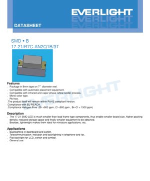
This document details the specifications of a surface-mount deep red LED utilizing a compact 17-21 package. This component is designed for modern electronic assembly, offering a significant reduction in size and weight compared to traditional lead-frame LEDs. Its primary advantages include: enabling smaller printed circuit board (PCB) designs, higher component assembly density, and ultimately contributing to more compact and lightweight end-user devices.
1.1 Core Features and Compliance
该 LED 以 8mm 载带形式提供,卷绕在 7 英寸直径的卷盘上,完全兼容自动化贴片组装设备。它适用于红外(IR)和气相回流焊工艺。该器件为单色类型,发射深红光。采用无铅材料制造,并符合关键的环境与安全法规,包括欧盟 RoHS 指令、欧盟 REACH 法规以及无卤素要求(Br <900 ppm,Cl <900 ppm,Br+Cl < 1500 ppm)。
1.2 Target Applications
Wannan LED ya dace da aikace-aikacen nuna alama da hasken baya da yawa. Amfanin gama gari sun haɗa da: hasken baya na dashboard da maɓalli, alamun yanayi da hasken maɓalli a cikin na'urorin sadarwa kamar waya da na'urar fax, hasken baya na LCD mai lebur, da aikace-aikacen nuna alama na gama gari waɗanda ke buƙatar ƙaramin hasken ja mai dogaro.
2. Technical Parameters: An In-depth Objective Interpretation
The following sections provide a detailed and objective analysis of the LED's electrical, optical, and thermal characteristics based on datasheet parameters. Unless otherwise specified, all ratings are specified at an ambient temperature (Ta) of 25°C.
2.1 Absolute Maximum Ratings
These ratings define the limits beyond which permanent damage to the device may occur. Operation at or beyond these conditions is not guaranteed and should be avoided in circuit design.
- Reverse Voltage (VR):5V. Exceeding this reverse voltage may cause junction breakdown.
- Continuous Forward Current (IF):25 mA. This is the maximum DC current recommended for reliable long-term operation.
- Peak Forward Current (IFP):60 mA. This current is only permitted under pulse conditions with a duty cycle of 1/10 and a frequency of 1 kHz, and cannot be used continuously.
- Power Dissipation (Pd):60 mW. This is the maximum power that can be dissipated by the package without exceeding its thermal limits.
- Electrostatic Discharge (ESD) Human Body Model (HBM):2000V. This indicates the device's sensitivity to static electricity; proper ESD handling procedures must be followed.
- Operating Temperature (Topr):-40°C to +85°C. This is the specified ambient temperature range in which the device can operate.
- Storage Temperature (Tstg):-40°C to +90°C. This is the storage temperature range for the device when it is not powered.
- Welding Temperature (Tsol):For reflow soldering, the peak temperature is specified as 260°C for a maximum of 10 seconds. For manual soldering, the soldering iron tip temperature should not exceed 350°C, with a maximum of 3 seconds per terminal.
2.2 Photoelectric Characteristics
These parameters define the optical output and electrical behavior of the LED under normal operating conditions (IF=20mA, Ta=25°C).
- Luminous Intensity (Iv):The range is from a minimum of 36.00 mcd to a maximum of 90.00 mcd. No typical value is specified, indicating performance is managed through a binning system (see Section 3).
- Viewing Angle (2θ1/2):The typical full viewing angle at half intensity is 140 degrees, providing a wide emission pattern.
- Peak Wavelength (λp):The typical wavelength for maximum optical power output is 639 nanometers (nm), located in the deep red region of the spectrum.
- Dominant Wavelength (λd):The perceived color wavelength range is from 625.5 nm to 637.5 nm. This is also managed through binning.
- Spectral Bandwidth (Δλ):The typical full width at half maximum (FWHM) of the emission spectrum is 20 nm.
- Forward Voltage (VF):At 20mA, the range is from 1.75V to 2.35V. This parameter is binned.
- Reverse Current (IR):Maximum 10 μA when a 5V reverse voltage is applied. The datasheet clearly states that this device is not designed for reverse operation; this test parameter is for quality assurance only.
Important Note:The datasheet specifies manufacturing tolerances: luminous intensity (±11%), dominant wavelength (±1nm), and forward voltage (±0.1V). These apply to the binned values.
3. Binning System Description
To ensure consistency in mass production, LEDs are sorted (binned) based on key performance parameters. This allows designers to select components that meet specific brightness and color requirements for their applications.
3.1 Luminous Intensity Binning
Based on the luminous intensity measured at IF=20mA, LEDs are sorted into four bins (N2, P1, P2, Q1). For example, the intensity of a Q1 bin LED will be between 72.00 and 90.00 mcd.
3.2 Dominant Wavelength Binning
Perceived color (hue) is controlled through three wavelength bins (E6, E7, E8). LEDs in the E6 bin have a dominant wavelength between 625.50 nm and 629.50 nm, producing a slightly different shade of red compared to the E8 bin (633.50 nm to 637.50 nm).
3.3 Forward Voltage Binning
Forward voltage is divided into three groups (0, 1, 2). This is crucial for designing current-limiting circuits, especially when driving multiple LEDs in series, to ensure uniform current distribution. The VF of grade 0 LEDs ranges from 1.75V to 1.95V, while that of grade 2 LEDs ranges from 2.15V to 2.35V.
4. Performance Curve Analysis
Although the provided PDF excerpt indicates the "Typical Electro-Optical Characteristics Curves" section, the specific charts (e.g., IV curve, relative intensity vs. current, relative intensity vs. temperature, spectral distribution) are not included in the text content. In the complete datasheet, these curves are essential for design. They typically show:
- Forward Current vs. Forward Voltage (IV Curve):It shows a non-linear relationship, which helps determine dynamic resistance and the required drive voltage for a given current.
- Relative Luminous Intensity vs. Forward Current:Shows how light output increases with current, typically exhibiting saturation effects at high currents.
- Relative luminous intensity vs. ambient temperature:Shows the decrease in light output as junction temperature rises, which is crucial for thermal management.
- Normalized Spectral Distribution:Plot the relative intensity versus wavelength to visually confirm the peak wavelength (639nm) and spectral bandwidth (20nm).
Designers should refer to the complete datasheet containing graphs to accurately simulate the LED's behavior under non-standard conditions (different current or temperature).
5. Mechanical and Packaging Information
5.1 Package Dimensions and Polarity
This LED uses a standard 17-21 SMD package outline. The key dimensions (in millimeters) are critical for PCB pad pattern design. The package is marked with a cathode for polarity identification. A typical pad pattern should have two pads corresponding to the anode and cathode terminals, with recommended pad sizes and spacing to ensure proper soldering and mechanical stability. The exact dimensions should be obtained from the "Package Dimensions" drawing in the datasheet.
5.2 Moisture Sensitivity and Packaging
An tattara wannan na'urar a cikin jakar shinge mai hana danshi tare da busassun abu, don hana shan danshin yanayi, wanda zai iya haifar da "fashewar gasa" (tsagewar kunshe) yayin aikin sake zafi mai zafi. Alamar da ke kan jakar ta ƙunshi mahimman bayanai don gano asali da aikace-aikace: Lambar Samfurin Abokin Ciniki (CPN), Lambar Samfura (P/N), Adadin Kunshe (QTY), da takamaiman lambobin rarrabuwa don Ƙarfin Haskakawa (CAT), Babban Tsawon Tsawon (HUE) da Ƙarfin Lantarki na Gaba (REF).
5.3 Reel and Tape Specifications
Components are supplied in embossed carrier tape, wound on 7-inch reels. The carrier tape dimensions (pocket size, pitch) and reel dimensions (hub diameter, flange diameter) are standardized for compatibility with automated assembly equipment. The quantity per reel is specified as 3000 pieces.
6. Welding and Assembly Guide
Adhering to these guidelines is crucial for assembly yield and long-term reliability.
6.1 Storage and Operation
- Do not open the moisture barrier bag until ready for use.
- After opening, unused LEDs should be stored in an environment of ≤30°C and ≤60% relative humidity (RH).
- The "floor life" after opening the bag is 168 hours (7 days). Unused components exceeding this period must be rebaked (60±5°C, 24 hours) and repacked with new desiccant before use.
- Always follow ESD (Electrostatic Discharge) safe handling procedures.
6.2 Reflow Soldering Temperature Profile
Defines the lead-free reflow soldering temperature profile. Key parameters include:
- Preheat:150-200°C, for 60-120 seconds.
- Time above liquidus (217°C):60-150 seconds.
- Peak temperature:Maximum 260°C.
- Time within peak temperature ±5°C:Maximum 10 seconds.
- Maximum heating rate:6°C/sec.
- Time above 255°C:Maximum 30 seconds.
- Maximum cooling rate:3°C per second.
Key rules:The same LED should not undergo reflow soldering more than twice.
6.3 Manual Soldering and Rework
If manual soldering is necessary, use a soldering iron with a tip temperature ≤350°C and heat each terminal for ≤3 seconds. Use a low-power soldering iron (≤25W) and allow a cooling interval of ≥2 seconds between terminals. The datasheet strongly advises against rework after LED soldering. If absolutely necessary, a dedicated dual-tip soldering iron must be used to simultaneously heat both terminals during removal to avoid mechanical stress, and the impact on LED characteristics must be verified.
7. Application Recommendations and Design Considerations
7.1 Rate limiting must be used.
LED is a current-driven device. The datasheet explicitly warns that a series current-limiting resistor must be used. The forward voltage has a negative temperature coefficient. Due to the exponential I-V characteristic of the diode, a small change can lead to a large variation in current, potentially causing thermal runaway and failure.MustUse. The forward voltage has a negative temperature coefficient. Due to the exponential IV characteristic of the diode, a small change may lead to a huge change in current, which may cause thermal runaway and failure.
7.2 Thermal management.
Although the package is small, the 60mW power dissipation limit must be observed. Operation at high ambient temperature or high current will reduce light output and lifetime. If operating near the maximum ratings, ensure sufficient PCB copper area or thermal vias are used.
7.3 Optical Design
The 140° viewing angle provides a wide, diffuse light pattern suitable for area lighting or indicator lights that need to be visible from all angles. For more focused light, an external lens or reflector is required.
8. Technical Comparison and Differentiation
The key differentiation of this 17-21 deep red LED lies in its combination of specific semiconductor material (AIGaInP) and a highly compact surface-mount package.
- Compared to old through-hole LEDs:Provide huge space savings, weight reduction, and compatibility with high-speed automated assembly, thereby lowering overall manufacturing costs.
- Compared to other SMD red LEDs:Compared to some other material systems used for red light emission, the use of AIGaInP technology typically offers higher efficiency and better stability in temperature performance. The choice of the specific 639nm peak/deep red color may be due to its visual distinctiveness or effectiveness in certain sensor applications.
- Compared to larger SMD packages (e.g., 3528, 5050):The 17-21 package is significantly smaller, enabling ultra-miniaturized designs, but total light output is generally lower due to its smaller chip size and thermal limitations.
8.1 Working Principle
Light is generated through the process of electroluminescence within an AIGaInP (aluminum gallium indium phosphide) semiconductor chip. When a forward voltage is applied, electrons and holes are injected into the active region of the semiconductor junction. As these charge carriers recombine, they release energy in the form of photons (light). The specific composition of the AIGaInP alloy determines the bandgap energy, which directly defines the wavelength (color) of the emitted light—in this case, a deep red light at approximately 639 nm.
9. Frequently Asked Questions (Based on Technical Parameters)
Q: Can I drive this LED directly with a 3.3V or 5V logic supply?
A: No. You must always use a series current-limiting resistor. The required resistor value is calculated using Ohm's Law: R = (Supply Voltage - LED Forward Voltage) / Desired Current. For a conservative design, using maximum VF (2.35V), a 3.3V supply, and a target current of 20mA: R = (3.3 - 2.35) / 0.02 = 47.5Ω. A standard 47Ω or 51Ω resistor is suitable.
Q: Why is luminous intensity given as a range and in bins?
A: Due to inherent variations in semiconductor manufacturing processes, the performance of individual LEDs differs slightly. Binning classifies them into groups with guaranteed minimum and maximum values, allowing designers to select the appropriate brightness grade based on their cost and performance requirements.
Q: What happens if the floor life exceeds 7 days after opening the bag?
A: Absorbed moisture can turn into steam during the reflow soldering process, potentially causing internal delamination or cracking. These components must be reprocessed by baking at 60°C for 24 hours before use.
Q: Is this LED suitable for automotive dashboard lighting?
A: Although "dashboard backlighting" is listed as an application, the datasheet includes an "Application Restrictions" section. It warns that high-reliability applications like automotive safety/security systems may require different, more rigorously certified products. For non-critical dashboard lighting, it might be suitable, but for safety-critical indicator lights, products specifically compliant with automotive standards (e.g., AEC-Q102) should be procured.
10. Practical Design and Usage Cases
Scenario: Designing a compact status indicator panel.A designer needs to use multiple deep red status LEDs on a component-dense control board. They selected the 17-21 LED for its small size. They specified the Q1 brightness bin and E7 wavelength bin to ensure all indicators have a bright, consistent color. For the PCB layout, they used the recommended land pattern from the datasheet. They designed the drive circuit using a 3.3V regulator, a 51Ω current-limiting resistor per LED (yielding approximately 18-20mA current), and placed small thermal relief pads. During assembly, they ensured factory-sealed reels were used within their workshop shelf life and followed the specified reflow soldering temperature profile. This resulted in a reliable, compact indicator system.
11. Technology Trends
The overall trend in LED technology (including indicator lights) is developing towards several key areas:
- Efficiency Enhancement:Ongoing improvements in materials science aim to produce more light (lumens) per unit of electrical input power (watts), thereby reducing energy consumption and thermal load.
- Miniaturization:Packaging continues to shrink (e.g., from 17-21 to smaller form factors like 10-05) to enable smaller electronic devices.
- Higher Reliability and Robustness:Improvements in packaging materials and die attach technology enhance lifespan and resistance to thermal cycling and moisture.
- Integration:The trend is to integrate multiple LEDs (e.g., RGB), control ICs, and even passive components into a single, smarter modular package.
- Standardization and Compliance:More stringent and extensive environmental regulations (RoHS, REACH, Halogen-Free) continue to drive material changes across the industry.
Detailed Explanation of LED Specification Terminology
Complete Explanation of LED Technical Terminology
I. Core Indicators of Optoelectronic Performance
| Terminology | Unit/Representation | Popular Explanation | Why It Is Important |
|---|---|---|---|
| Luminous Efficacy | lm/W (lumens per watt) | The luminous flux emitted per watt of electrical power; the higher the value, the more energy-efficient it is. | Directly determines the energy efficiency rating and electricity cost of the luminaire. |
| Luminous Flux | lm (lumen) | The total amount of light emitted by a light source, commonly known as "brightness". | Determines whether a luminaire is bright enough. |
| Viewing Angle | ° (degrees), such as 120° | The angle at which the light intensity drops to half determines the beam width. | Affects the illumination range and uniformity. |
| Correlated Color Temperature (CCT) | K (Kelvin), e.g., 2700K/6500K | The warmth or coolness of light color; lower values are yellowish/warm, higher values are whitish/cool. | Determines the lighting atmosphere and suitable application scenarios. |
| Color Rendering Index (CRI / Ra) | Unitless, 0–100 | The ability of a light source to restore the true color of an object, Ra≥80 is recommended. | Affects color authenticity, used in high-demand places such as shopping malls and art galleries. |
| SDCM (Standard Deviation of Color Matching) | MacAdam ellipse steps, e.g., "5-step" | A quantitative indicator of color consistency; a smaller step number indicates higher color consistency. | Ensure no color difference among the same batch of luminaires. |
| Dominant Wavelength | nm (nanometer), e.g., 620nm (red) | The wavelength values corresponding to the colors of colored LEDs. | Determines the hue of monochromatic LEDs such as red, yellow, and green. |
| Spectral Distribution | Wavelength vs. Intensity Curve | Display the intensity distribution of light emitted by the LED across various wavelengths. | Affects color rendering and color quality. |
II. Electrical Parameters
| Terminology | Symbol | Popular Explanation | Design Considerations |
|---|---|---|---|
| Forward Voltage | Vf | The minimum voltage required to light up an LED, similar to a "starting threshold". | The driving power supply voltage must be ≥ Vf; voltages add up when multiple LEDs are connected in series. |
| Forward Current | If | The current value that makes the LED emit light normally. | Constant current drive is often used, as the current determines brightness and lifespan. |
| Maximum Pulse Current (Pulse Current) | Ifp | Peak current that can be withstood for a short period, used for dimming or flashing. | Pulse width and duty cycle must be strictly controlled, otherwise overheating damage will occur. |
| Reverse Voltage | Vr | The maximum reverse voltage that an LED can withstand; exceeding it may cause breakdown. | Circuit ina buƙatar hana jujjuyawar baya ko ƙarfin wutar lantarki. |
| Thermal Resistance | Rth (°C/W) | The resistance to heat flow from the chip to the solder joint. A lower value indicates better heat dissipation. | High thermal resistance requires a more robust thermal design; otherwise, the junction temperature will increase. |
| ESD Immunity | V (HBM), e.g., 1000V | The higher the ESD immunity rating, the more resistant the device is to electrostatic damage. | Anti-static measures must be taken during production, especially for high-sensitivity LEDs. |
III. Thermal Management and Reliability
| Terminology | Key Metrics | Popular Explanation | Impact |
|---|---|---|---|
| Junction Temperature | Tj (°C) | The actual operating temperature inside the LED chip. | For every 10°C reduction, lifespan may double; excessively high temperatures cause lumen depreciation and color shift. |
| Lumen Depreciation | L70 / L80 (hours) | The time required for brightness to drop to 70% or 80% of its initial value. | Directly defines the "service life" of an LED. |
| Lumen Maintenance | % (e.g., 70%) | The percentage of remaining brightness after a period of use. | Characterizes the ability to maintain brightness after long-term use. |
| Color Shift | Δu′v′ or MacAdam ellipse | The degree of color change during use. | Affects the color consistency of the lighting scene. |
| Thermal Aging | Material performance degradation | Deterioration of packaging materials due to prolonged high temperatures. | May lead to decreased brightness, color shift, or open-circuit failure. |
IV. Packaging and Materials
| Terminology | Common Types | Popular Explanation | Characteristics and Applications |
|---|---|---|---|
| Packaging Type | EMC, PPA, Ceramic | The housing material that protects the chip and provides optical and thermal interfaces. | EMC tahan panas baik, biaya rendah; keramik pendinginan unggul, umur panjang. |
| Struktur chip | Face-up, Flip Chip | Chip electrode arrangement method. | Flip Chip offers better heat dissipation and higher luminous efficacy, suitable for high-power applications. |
| Phosphor coating | YAG, silicate, nitride | Covered on the blue light chip, partially converted into yellow/red light, mixed into white light. | Different phosphors affect luminous efficacy, color temperature, and color rendering. |
| Lens/Optical design | Flat, Microlens, Total Internal Reflection | Optical structure on the encapsulation surface, controlling light distribution. | Determine the beam angle and light distribution curve. |
V. Quality Control and Binning
| Terminology | Binning Content | Popular Explanation | Purpose |
|---|---|---|---|
| Luminous Flux Classification | Codes such as 2G, 2H | Group by brightness level, each group has a minimum/maximum lumen value. | Ensure consistent brightness for the same batch of products. |
| Voltage binning | Codes such as 6W, 6X | Group by forward voltage range. | Facilitates driver matching and improves system efficiency. |
| Color binning | 5-step MacAdam Ellipse | Group by color coordinates to ensure colors fall within a minimal range. | Ensure color consistency to avoid uneven color within the same luminaire. |
| Color temperature binning | 2700K, 3000K, etc. | Grouped by color temperature, each group has a corresponding coordinate range. | To meet the color temperature requirements of different scenarios. |
VI. Testing and Certification
| Terminology | Standards/Testing | Popular Explanation | Significance |
|---|---|---|---|
| LM-80 | Lumen Maintenance Test | Record brightness attenuation data under constant temperature conditions over a long period of illumination. | Used to estimate LED lifetime (in conjunction with TM-21). |
| TM-21 | Lifespan Projection Standard | Estimating lifespan under actual operating conditions based on LM-80 data. | Provide scientific life prediction. |
| IESNA Standard | Illuminating Engineering Society Standard | Covers optical, electrical, and thermal testing methods. | Industry-recognized basis for testing. |
| RoHS / REACH | Environmental Certification | Ensure products are free from hazardous substances (e.g., lead, mercury). | Market access requirements for entering the international market. |
| ENERGY STAR / DLC | Energy Efficiency Certification | Energy Efficiency and Performance Certification for Lighting Products. | Commonly used in government procurement and subsidy programs to enhance market competitiveness. |