Table of Contents
- 1. Product Overview
- 1.1 Core Features and Applications
- 2. Technical Specifications and In-Depth Interpretation
- 2.1 Absolute Maximum Ratings
- 2.2 Electro-Optical Characteristics (Ta=25°C)
- 3. Binning System Explanation
- 3.1 Luminous Intensity Binning
- 3.2 Forward Voltage Binning
- 3.3 Chromaticity Coordinate Binning
- 4. Performance Curve Analysis
- 4.1 Forward Current vs. Forward Voltage (I-V Curve)
- 4.2 Luminous Intensity vs. Forward Current
- 4.3 Luminous Intensity vs. Ambient Temperature
- 4.4 Forward Current Derating Curve
- 4.5 Spectral Distribution
- 5. Mechanical and Package Information
- 5.1 Package Dimensions
- 5.2 Recommended Pad Layout
- 6. Soldering and Assembly Guidelines
- 6.1 Current Limiting Requirement
- 6.2 Storage and Moisture Sensitivity
- 6.3 Bayanin Siffar Solder Reflow
- 6.4 Solder da Hannu
- 7. Bayanin Marufi da Oda
- 7.1 Ƙayyadaddun Reel da Tepe
- 7.2 Label Explanation
- 8. Application Design Considerations
- 8.1 Circuit Design
- 8.2 Thermal Management
- 8.3 Optical Design
- 9. Technical Comparison and Differentiation
- 10. Frequently Asked Questions (FAQs)
- 10.1 Can I drive this LED without a current-limiting resistor?
- 10.2 Me ya sa kewayon ƙarfin haske ya yi fadi sosai (90-180 mcd)?
- 10.3 Sau nawa zan iya sake yin reflow solder akan wannan LED?
- 10.4 Me ake nufi da "Pb-free" a cikin mahallin solder?
- 11. Misalai na Zane da Amfani na Aiki
- 11.1 Misali na 1: Mai Nuna Matsayi Mai Sauƙi
- 11.2 Misali na 2: Tsarin Hasken Baya don LCD Ƙarami
- 12. Ka'idar Aiki
- 13. Trends na Fasaha
- LED Specification Terminology
- Photoelectric Performance
- Electrical Parameters
- Thermal Management & Reliability
- Packaging & Materials
- Quality Control & Binning
- Testing & Certification
1. Product Overview
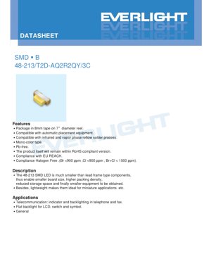
The 48-213/T2D-AQ2R2QY/3C is a surface-mount device (SMD) LED in a compact 1206 package format. This mono-color, pure white LED is designed for modern electronic applications requiring high-density component placement and reliable performance. Its primary advantages include a significantly reduced footprint compared to leaded LEDs, enabling smaller printed circuit board (PCB) designs and higher packing density. The component is lightweight, making it suitable for miniature and portable applications. It is compliant with RoHS, EU REACH, and halogen-free standards (Br <900 ppm, Cl <900 ppm, Br+Cl < 1500 ppm), ensuring environmental and safety compliance for global markets.
1.1 Core Features and Applications
The LED is supplied on 8mm tape mounted on a 7-inch diameter reel, making it fully compatible with high-speed automatic pick-and-place assembly equipment. It is designed to withstand standard infrared (IR) and vapor phase reflow soldering processes, which are common in volume manufacturing.
Typical Applications:
- Telecommunication Equipment: Alamomin nuna da haske na baya don maɓallai ko nunawa a cikin wayoyi da na'urorin fakis.
- Kayan Lantarki na Masu Amfani: Haske na baya mai lebur don nunin ruwa mai santsi (LCDs), haske na baya don maɓalli da alamomi akan filayen sarrafawa.
- Nuni na Gabaɗaya: Duk aikace-aikacen da ke buƙatar ƙaramin, amintaccen, da haske mai haske na nuni.
2. Technical Specifications and In-Depth Interpretation
Wannan sashe yana ba da cikakken bincike na cikakkun ƙididdiga na iyaka da halayen lantarki da haske da aka ayyana a cikin takardar bayanai. Fahimtar waɗannan sigogi yana da mahimmanci don ƙirar da'ira mai dogaro da kuma tabbatar da dadewar LED.
2.1 Absolute Maximum Ratings
These ratings define the limits beyond which permanent damage to the device may occur. Operation under or at these limits is not guaranteed.
- Reverse Voltage (VR): 5V. Exceeding this voltage in reverse bias can cause immediate junction breakdown.
- Continuous Forward Current (IF): 25mA. The DC current that can be continuously passed through the LED.
- Peak Forward Current (IFP): 100mA. This is the maximum pulsed current, permissible only under specific conditions (duty cycle of 1/10 at 1kHz). It is useful for brief, high-brightness pulses but must not be used for continuous operation.
- Power Dissipation (Pd): 95mW. This is the maximum amount of power the package can dissipate as heat, calculated as VF * IF. Exceeding this limit risks overheating and accelerated degradation.
- Operating & Storage Temperature: -40°C to +85°C (operating), -40°C to +90°C (storage). These wide ranges make the LED suitable for industrial and automotive environments.
- Electrostatic Discharge (ESD): 150V (Human Body Model). This is a relatively low ESD tolerance, indicating the device is sensitive to static electricity. Proper ESD handling procedures are mandatory.
- Soldering Temperature: LED na iya jurewa haɗaɗɗiyar sake kunnawa tare da zafin jiki mai girma na 260°C har zuwa dakika 10, ko haɗaɗɗiyar hannu a 350°C har zuwa dakika 3 a kowace tasha.
2.2 Electro-Optical Characteristics (Ta=25°C)
Waɗannan su ne madaidaicin sigogin aiki a ƙarƙashin daidaitattun yanayin gwaji. Masu ƙira yakamata su yi amfani da madaidaicin (Typ.) ko ƙimar iyaka/iƙƙa a matsayin tushen ƙirar su.
- Ƙarfin Haskakawa (Iv): 90 zuwa 180 millicandela (mcd) a gaba mai gudana (IF) na 5mA. Ana sarrafa faɗin kewayon ta hanyar tsarin rarrabawa (cikakke a Sashe na 3). Kusurwar kallo (2θ1/2) yawanci digiri 130 ne, yana ba da faɗaɗaɗɗen tsarin haske.
- Ƙarfin Wutar Gaba (VF): 2.7V zuwa 3.2V a IF=5mA. Wannan siga yana da jurewar ±0.05V. Ƙarfin lantarki na gaba yana da mahimmanci don ƙididdige ƙimar resistor mai iyakancewar halin yanzu: R = (Vwadata - VF) / IF.
- Halin Yanzu na Baya (IR): Matsakaicin 50µA a VR=5V. Takardar bayanai ta bayyana a sarari cewa yanayin ƙarfin lantarki na baya don dalilai na gwaji ne kawai, kuma bai kamata a yi amfani da LED a cikin karkatar da baya a cikin da'ira ta ainihi ba.
3. Binning System Explanation
Don tabbatar da daidaito a cikin samar da yawa, ana rarraba LED zuwa "kwantena" bisa mahimman sigogi na aiki. Wannan yana ba masu zane damar zaɓar sassa waɗanda suka dace da takamaiman buƙatun haske da ƙarfin lantarki don aikace-aikacensu.
3.1 Luminous Intensity Binning
An rarraba ƙarfin haskakawa zuwa manyan kwantena guda uku a IF=5mA:
- Kwanten Q2: 90 mcd (Mafi ƙanƙanta) zuwa 112 mcd (Mafi girma)
- Kwanten R1: 112 mcd (Mafi ƙanƙanta) zuwa 140 mcd (Mafi girma)
- Kwanten R2: 140 mcd (Min) to 180 mcd (Max)
The product code "AQ2R2QY" indicates this specific part is from intensity bin Q2 and R2. A tolerance of ±11% applies within each bin.
3.2 Forward Voltage Binning
The forward voltage is grouped and binned to help with power supply design and current regulation. The bins (Group Q) are defined in 0.1V steps:
- Bin 29: 2.7V to 2.8V
- Bin 30: 2.8V zuwa 2.9V
- Bin 31: 2.9V zuwa 3.0V
- Bin 32: 3.0V zuwa 3.1V
- Bin 33: 3.1V zuwa 3.2V
Iyakar jurewa don ƙarfin lantarki na gaba a cikin bin shine ±0.05V.
3.3 Chromaticity Coordinate Binning
For white LEDs, color consistency is critical. The chromaticity coordinates (CIE x, y) define the precise color point on the CIE 1931 diagram. The datasheet defines six bins (A1 through A6), each representing a small quadrilateral area on the color chart. The product's color is guaranteed to fall within the specified polygon with a tolerance of ±0.01 in both x and y coordinates. This tight control ensures minimal visible color variation between different LEDs in an array or backlight.
4. Performance Curve Analysis
The datasheet provides several characteristic curves that illustrate the LED's behavior under varying conditions. These are essential for advanced design considerations.
4.1 Forward Current vs. Forward Voltage (I-V Curve)
This curve shows the non-linear relationship between current and voltage. The forward voltage increases logarithmically with current. For stable operation, a constant current driver or a current-limiting resistor is mandatory, as a small increase in voltage beyond the nominal VF can cause a large, potentially destructive increase in current.
4.2 Luminous Intensity vs. Forward Current
The light output is approximately proportional to the forward current. However, efficiency (lumens per watt) may drop at very high currents due to increased heat generation within the chip. Operating near the maximum continuous current (25mA) may reduce long-term reliability.
4.3 Luminous Intensity vs. Ambient Temperature
The light output of an LED decreases as the junction temperature rises. This curve quantifies that derating. For applications operating in high ambient temperatures, the drive current may need to be reduced to maintain brightness or to prevent overheating.
4.4 Forward Current Derating Curve
This is a critical curve for thermal management. It defines the maximum allowable continuous forward current as a function of the ambient temperature. As temperature increases, the maximum safe current decreases to keep the junction temperature within safe limits and prevent thermal runaway.
4.5 Spectral Distribution
Lanƙwasa bakan yana nuna ƙarfin dangi da aka fitar a cikin tsayin daban-daban. LED mai tsantsar fari yawanci yana amfani da guntuwar InGaN shuɗi da aka haɗa da phosphor rawaya. Bakan zai nuna kololuwa a yankin shuɗi (kusan 450nm) da faɗaɗɗen fitarwa a yankin rawaya/kore daga phosphor, suna haɗuwa don samar da haske fari.
5. Mechanical and Package Information
5.1 Package Dimensions
LED ya yi daidai da daidaitaccen girman kunshin 1206 (inci) ko 3216 (awo). Muhimman girma (a cikin mm) sune:
- Tsawon Gabaɗaya: 2.25 ±0.20
- Tsawir Faɗi Daya: 1.85 ±0.20
- Tsawir Tsayi Daya: 1.45 ±0.10
- Girman Terminal: 0.72 ±0.10 (tsayi), 1.20 x 0.60 (tabo)
Tolerances are ±0.1mm unless otherwise specified. A cathode mark is clearly indicated on the package for correct polarity orientation during assembly.
5.2 Recommended Pad Layout
The datasheet includes a suggested land pattern (pad design) for PCB layout. The recommended pad size is 1.40mm x 1.10mm. It is emphasized that this is for reference only, and the pad dimensions should be optimized based on the specific solder paste, stencil, and assembly process used by the manufacturer.
6. Soldering and Assembly Guidelines
Sarrafa da solder daidai yana da mahimmanci ga yawan amfanin ƙasa da amincin aiki.
6.1 Current Limiting Requirement
Tilas: Dole ne a koyaushe a yi amfani da resistor mai iyakancewar halin yanzu na waje a jere tare da LED. LED na'urar da aka tuƙa ta halin yanzu ce, kuma ƙarfinta na gaba yana da ma'auni mara kyau na zafin jiki. Ba tare da resistor ba, ko da ƙaramin ƙaruwa a cikin ƙarfin wadata ko faɗuwar VF saboda dumama zai iya haifar da haɓakar halin yanzu da ba a sarrafa ba, wanda zai haifar da gazawar nan take.
6.2 Storage and Moisture Sensitivity
The components are packaged in a moisture-resistant bag with desiccant.
- Before Opening: Store at ≤30°C and ≤90% Relative Humidity (RH).
- After Opening: The "floor life" is 1 year at ≤30°C and ≤60% RH. Unused parts should be resealed in a moisture-proof bag.
- Baking: If the desiccant indicator changes color or the storage time is exceeded, the LEDs must be baked at 60 ±5°C for 24 hours before reflow soldering to remove absorbed moisture and prevent "popcorning" damage during reflow.
6.3 Bayanin Siffar Solder Reflow
A lead-free reflow profile is specified:
- Pre-heating: 150-200°C for 60-120 seconds.
- Time Above Liquidus (TAL): 60-150 seconds above 217°C.
- Peak Temperature: 260°C maximum, held for no more than 10 seconds.
- Ramp Rates: Maximum 6°C/sec heating, 3°C/sec cooling.
Critical Notes:
- Reflow soldering should not be performed more than two times.
- Avoid mechanical stress on the LED body during heating and cooling.
- Do not warp the PCB after soldering, as this can crack the LED or its solder joints.
6.4 Solder da Hannu
If hand soldering is necessary, use a soldering iron with a tip temperature below 350°C. Contact time per terminal should be less than 3 seconds. Use an iron with a power rating of 25W or less. Allow a minimum interval of 2 seconds between soldering each terminal to prevent excessive heat buildup.
7. Bayanin Marufi da Oda
7.1 Ƙayyadaddun Reel da Tepe
The LEDs are supplied in embossed carrier tape on 7-inch reels.
- Carrier Tape Width: 8mm.
- Pocket Pitch: 4mm.
- Quantity per Reel: 3000 pieces.
- Reel Dimensions: Standard 7-inch diameter with specific hub and flange dimensions as per EIA-481.
7.2 Label Explanation
The reel label contains critical information for traceability and verification:
- P/N: Full product number (48-213/T2D-AQ2R2QY/3C).
- CAT: Luminous Intensity Rank (e.g., Q2, R2).
- HUE: Chromaticity Coordinates and Dominant Wavelength Rank.
- REF: Forward Voltage Rank (e.g., from Group Q bins).
- LOT No: Manufacturing lot number for traceability.
8. Application Design Considerations
8.1 Circuit Design
Always calculate the series resistor using the maximum forward voltage from the datasheet (3.2V) to ensure sufficient current limiting under all conditions. For a 5V supply and a target current of 5mA: R = (5V - 3.2V) / 0.005A = 360Ω. The nearest standard value (360Ω or 390Ω) would be chosen. The resistor power rating should be I2R = (0.005)2 * 360 = 0.009W, so a standard 1/10W or 1/8W resistor is more than adequate.
8.2 Thermal Management
While the 1206 package has no dedicated thermal pad, heat is conducted away through the two solder terminals. Ensure the PCB has adequate copper area connected to the LED pads, especially if operating near the maximum current or in high ambient temperatures. Avoid placing the LED near other heat-generating components.
8.3 Optical Design
The wide 130-degree viewing angle makes this LED suitable for applications requiring broad, diffuse illumination rather than a focused beam. For indicator applications, consider the required luminous intensity at the viewing angle; brightness falls off towards the edges of the viewing cone.
9. Technical Comparison and Differentiation
The 48-213 LED, in its 1206 package, offers a balance between size, brightness, and ease of assembly.
- vs. Larger Packages (e.g., 3528, 5050): The 1206 is significantly smaller, saving board space but typically offering lower total light output due to its smaller chip size.
- vs. Smaller Packages (e.g., 0402, 0603): The 1206 is easier to handle and solder manually if needed, and often can handle slightly higher currents, resulting in higher brightness.
- vs. Non-binned LEDs: The defined binning structure for intensity, voltage, and color provides predictable performance, which is essential for applications requiring uniform appearance in multi-LED arrays or consistent brightness across production batches.
10. Frequently Asked Questions (FAQs)
10.1 Can I drive this LED without a current-limiting resistor?
A'a. Ana gargadin hakan a cikin takardar bayanan. Dole ne a tuka LED ta hanyar tushen halin yanzu na dawwama ko, a mafi yawan lokuta, tushen wutar lantarki a jere tare da resistor mai iyakancewar halin yanzu. Haɗa kai kai tsaye zuwa tushen wutar lantarki zai haifar da gazawa.
10.2 Me ya sa kewayon ƙarfin haske ya yi fadi sosai (90-180 mcd)?
Wannan shi ne cikakken kewayon da zai yiwu a cikin samarwa. Ana rarraba raka'o'i ɗaya-ɗaya zuwa ƙananan rukunoni masu matsi (Q2, R1, R2). Lokacin yin oda, kuna ƙayyadad da lambar rukunin (misali, AQ2R2QY) don samun LED daga takamaiman rukunoni na ƙarfi da launi, yana tabbatar da daidaito a cikin samfuran ku.
10.3 Sau nawa zan iya sake yin reflow solder akan wannan LED?
Takardar bayanan ta bayyana cewa bai kamata a yi reflow soldering fiye da sau biyu. Zagayowar sake kunnawa ta uku tana da haɗarin lalata ɗaurin waya na ciki ko guntun LED saboda matsanancin zafi mai tarawa.
10.4 Me ake nufi da "Pb-free" a cikin mahallin solder?
Yana nufin tashoshin waje na LED an kammala su tare da fakitin da ba shi da gubar (yawanci tin). Ƙayyadaddun bayanin sake kunnawa (kololuwar 260°C) an tsara shi don manna gami maras gubar (misali, SAC305), waɗanda ke da mafi girman wurin narkewa fiye da tsohuwar gami ta tin-lead.
11. Misalai na Zane da Amfani na Aiki
11.1 Misali na 1: Mai Nuna Matsayi Mai Sauƙi
Labari: Alamarar da'awar da'awar 3.3V logic board.
Design: Yi amfani da 5mA drive current don kyakkyawan gani tare da ƙarancin amfani da wutar lantarki. R = (3.3V - 3.2V) / 0.005A = 20Ω. Tunda 3.2V shine matsakaicin VF, ainihin halin yanzu na iya zama ɗan sama idan LED's VF ya fi ƙasa. 33Ω ko 47Ω resistor zai samar da mafi ra'ayi kuma tsayayye halin yanzu. Haɗa LED tare da cathode (alama gefe) zuwa ƙasa.
11.2 Misali na 2: Tsarin Hasken Baya don LCD Ƙarami
Labari: Uniform backlighting yana buƙatar 10 LEDs.
Design: Don tabbatar da daidaiton haske, duk LEDs yakamata su kasance daga rukunin ƙarfi ɗaya (misali, R2). Yakamata a haɗa su a layi daya, kowannensu yana da nasa na musamman mai iyakance halin yanzu. Haɗa LEDs da yawa a layi daya zuwa resistor guda ba a ba da shawarar ba saboda bambance-bambance a cikin VF, wanda zai iya haifar da rashin daidaiton raba halin yanzu da haske.
12. Ka'idar Aiki
This is a semiconductor photonic device. It is based on an Indium Gallium Nitride (InGaN) chip. When a forward voltage exceeding the diode's junction potential (VF) is applied, electrons and holes recombine within the active region of the semiconductor, releasing energy in the form of photons (light). In a "pure white" LED, the primary chip emits blue light. This blue light excites a layer of yellow phosphor coating the chip. The combination of the blue light from the chip and the yellow light from the phosphor is perceived by the human eye as white light. This method is known as phosphor-converted white light generation.
13. Trends na Fasaha
SMD LEDs in packages like the 1206 represent a mature and widely adopted technology. The general industry trend is towards:
- Increased Efficiency: Higher luminous efficacy (more lumens per watt) through improvements in chip design and phosphor technology.
- Miniaturization: Continued reduction in package size (e.g., 0402, 0201) for ultra-compact devices, though this often trades off maximum power handling.
- Improved Color Quality: Development of phosphors to achieve higher Color Rendering Index (CRI) values and more consistent color points across production batches.
- Integrated Solutions: Growth of LEDs with built-in current regulation (constant current LED drivers) or protection features (ESD, reverse polarity) within the package, simplifying circuit design.
The 48-213 LED, with its well-defined specifications, reliable performance, and standard package, remains a fundamental and versatile component in the optoelectronics landscape, suitable for a vast array of indicator and backlighting applications.
LED Specification Terminology
Cikakken bayanin kalmomin fasaha na LED
Photoelectric Performance
| Kalma | Naúrar/Wakilci | Bayani Mai Sauƙi | Me Ya Sa Yake Da Muhimmanci |
|---|---|---|---|
| Haske | lm/W (lumens kowane watt) | Haske da ake samu kowane watt na wutar lantarki, mafi girma yana nufin mafi inganci a amfani da makamashi. | Yana ƙayyadaddun matakin ingancin amfani da makamashi da farashin wutar lantarki kai tsaye. |
| Yawan Haske | lm (lumens) | Total light emitted by source, commonly called "brightness". | Determines if the light is bright enough. |
| Viewing Angle | ° (degrees), e.g., 120° | Angle where light intensity drops to half, determines beam width. | Affects illumination range and uniformity. |
| CCT (Color Temperature) | K (Kelvin), e.g., 2700K/6500K | Warmth/coolness of light, lower values yellowish/warm, higher whitish/cool. | Determines lighting atmosphere and suitable scenarios. |
| CRI / Ra | Unitless, 0–100 | Ability to render object colors accurately, Ra≥80 is good. | Affects color authenticity, used in high-demand places like malls, museums. |
| SDCM | MacAdam ellipse steps, e.g., "5-step" | Color consistency metric, smaller steps mean more consistent color. | Ensures uniform color across same batch of LEDs. |
| Wavelength ya Kuvutia | nm (nanometers), mfano, 620nm (nyekundu) | Wavelength inayolingana na rangi ya LEDs zenye rangi. | Huamua uonekano wa rangi ya LEDs za rangi moja nyekundu, manjano, kijani. |
| Usambazaji wa Spectral | Mkunjo wa Wavelength dhidi ya ukali | Yana nuna haske a tsakanin tsayin daddare. | Yana shafar yadda ake nuna launi da inganci. |
Electrical Parameters
| Kalma | Symbol | Bayani Mai Sauƙi | Design Considerations |
|---|---|---|---|
| Forward Voltage | Vf | Minimum voltage to turn on LED, like "starting threshold". | Driver voltage must be ≥Vf, voltages add up for series LEDs. |
| Forward Current | If | Current value for normal LED operation. | Usually constant current drive, current determines brightness & lifespan. |
| Matsakaicin Ƙarfin Halin Yanzu na Bugun Jini | Ifp | Matsakaicin ƙarfin halin yanzu da za a iya jurewa na ɗan lokaci, ana amfani dashi don dushewa ko walƙiya. | Pulse width & duty cycle must be strictly controlled to avoid damage. |
| Reverse Voltage | Vr | Max reverse voltage LED can withstand, beyond may cause breakdown. | Circuit must prevent reverse connection or voltage spikes. |
| Thermal Resistance | Rth (°C/W) | Resistance to heat transfer from chip to solder, lower is better. | High thermal resistance requires stronger heat dissipation. |
| ESD Immunity | V (HBM), e.g., 1000V | Ability to withstand electrostatic discharge, higher means less vulnerable. | Anti-static measures needed in production, especially for sensitive LEDs. |
Thermal Management & Reliability
| Kalma | Metric Muhimmi | Bayani Mai Sauƙi | Tasiri |
|---|---|---|---|
| Junction Temperature | Tj (°C) | Yanayin aiki na ainihi a cikin guntu LED. | Kowane raguwar 10°C na iya ninka tsawon rayuwa; yana da yawa yana haifar da lalacewar haske, canjin launi. |
| Lumen Depreciation | L70 / L80 (hours) | Time for brightness to drop to 70% or 80% of initial. | Directly defines LED "service life". |
| Lumen Maintenance | % (e.g., 70%) | Yawan haske da ya rage bayan lokaci. | Yana nuna riƙon haske a cikin dogon lokaci amfani. |
| Canjin Launi | Δu′v′ ko MacAdam ellipse | Matsayin canjin launi yayin amfani. | Yana shafar daidaiton launi a cikin yanayin haske. |
| Thermal Aging | Material degradation | Deterioration due to long-term high temperature. | May cause brightness drop, color change, or open-circuit failure. |
Packaging & Materials
| Kalma | Common Types | Bayani Mai Sauƙi | Features & Applications |
|---|---|---|---|
| Nau'in Kunshin | EMC, PPA, Ceramic | Kayan gini da ke kare guntu, yana samar da hanyar sadarwa ta gani/thermal. | EMC: mai kyau ga jure zafi, ƙarancin farashi; Ceramic: mafi kyau kawar da zafi, tsawon rai. |
| Tsarin Guntu | Front, Flip Chip | Chip electrode arrangement. | Flip chip: better heat dissipation, higher efficacy, for high-power. |
| Phosphor Coating | YAG, Silicate, Nitride | Covers blue chip, converts some to yellow/red, mixes to white. | Phosphors daban-daban suna tasiri aikin, CCT, da CRI. |
| Lens/Optics | Flat, Microlens, TIR | Tsarin gani a saman da ke sarrafa rarraba haske. | Yana ƙayyade kusurwar kallo da lanƙwasa rarraba haske. |
Quality Control & Binning
| Kalma | Binning Content | Bayani Mai Sauƙi | Purpose |
|---|---|---|---|
| Luminous Flux Bin | Code e.g., 2G, 2H | Grouped by brightness, each group has min/max lumen values. | Ensures uniform brightness in same batch. |
| Voltage Bin | Code e.g., 6W, 6X | Grouped by forward voltage range. | Facilitates driver matching, improves system efficiency. |
| Color Bin | 5-step MacAdam ellipse | An rarraba ta hanyar daidaitawar launi, tabbatar da ƙaramin kewayon. | Yana tabbatar da daidaiton launi, yana guje wa rashin daidaiton launi a cikin kayan aiki. |
| CCT Bin | 2700K, 3000K etc. | An rarraba ta CCT, kowanne yana da ƙayyadaddun kewayon daidaitawa. | Yana biyan buƙatun CCT na fage daban-daban. |
Testing & Certification
| Kalma | Standard/Test | Bayani Mai Sauƙi | Significance |
|---|---|---|---|
| LM-80 | Lumen maintenance test | Long-term lighting at constant temperature, recording brightness decay. | Ana amfani don kimanta rayuwar LED (tare da TM-21). |
| TM-21 | Ma'aunin kimanta rayuwa | Yana kiyasin rayuwa a ƙarƙashin yanayi na ainihi bisa bayanan LM-80. | Yana ba da hasashen rayuwa na kimiyya. |
| IESNA | Illuminating Engineering Society | Yana'anta gwamnatun haske, lantarki, da zafi. | Tushen gwaji da masana'antu suka amince da shi. |
| RoHS / REACH | Takaddun shaida na muhalli. | Yana tabbatar da babu abubuwa masu cutarwa (darma, mercury). | Manufar samun kasuwa a duniya. |
| ENERGY STAR / DLC | Takardar shaidar ingancin makamashi. | Takardar shaidar ingancin makamashi da aiki don hasken wuta. | Ana amfani da shi a cikin sayayyar gwamnati, shirye-shiryen tallafi, yana haɓaka gasa. |