Table of Contents
- 1. Product Overview
- 1.1 Core Advantages
- 1.2 Target Market and Applications
- 2. In-depth Technical Parameter Analysis
- 2.1 Photoelectric Characteristics
- 2.2 Absolute Maximum Ratings and Electrical Parameters
- 2.3 Thermal Characteristics
- 3. Grading System Description
- 3.1 Luminous Flux Grading
- 3.2 Bincike na ƙarfin lantarki mai gaba
- 3.3 Chromaticity and Correlated Color Temperature Grading
- 3.4 Color Rendering Index Grading
- 4. Performance Curve Analysis and Design Considerations
- 4.1 Relationship Between Current and Luminous Flux/Voltage
- 4.2 Temperature Dependence
- 4.3 Spectral Distribution
- 5. Mechanical Structure, Packaging and Assembly Information
- 5.1 Packaging and Dimensions
- 5.2 Soldering Guidelines
- 5.3 Polarity Identification
- 6. Ordering Information and Model Decoding
- 7. Application Suggestions and Design Considerations
- 7.1 Drive Circuit Design
- 7.2 Thermal Management Design
- 7.3 Optical Design
- 8. Technical Comparison and Market Background
- 9. Frequently Asked Questions
- 10. Practical Application Cases
- 11. Working Principles
- 12. Technical Trends and Background
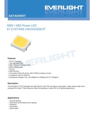
1. Product Overview
67-21ST is a surface-mount mid-power LED in a PLCC-2 package. It is a white LED designed to provide a balance of performance, efficiency, and reliability for general lighting applications. Its compact form factor and standardized package make it suitable for automated assembly processes.
1.1 Core Advantages
The main advantages of this LED package include:
- High luminous efficacy:It provides good light output relative to its power consumption.
- High Color Rendering Index:It provides a CRI rating of at least 60 to 90, ensuring good color reproduction. The standard mass-produced model is the CRI 80 (minimum) series.
- Wide Viewing Angle:Typical viewing angle is 120 degrees, providing broad and uniform illumination.
- Low power consumption:Standard operating current is 60mA, with high energy efficiency.
- Environmental Compliance:产品无铅,符合欧盟RoHS和REACH法规,并满足无卤标准(Br<900ppm,Cl<900ppm,Br+Cl<1500ppm)。
- ANSI Binning:Follow standardized chromaticity binning to ensure color consistency across different production batches.
1.2 Target Market and Applications
This LED is an ideal solution for numerous lighting applications requiring reliable, efficient, and compact light sources. The main application areas include:
- General Lighting:Integrated into residential, commercial, and industrial luminaires.
- Decorative and Entertainment Lighting:For accent lighting, signage, and stage lighting.
- Indicator lights and switch lights:Suitable for button backlighting, panels, and status indicator lights.
- General lighting:Suitable for any application requiring a diffuse, wide-angle white light source.
2. In-depth Technical Parameter Analysis
This section provides a detailed and objective interpretation of the key performance parameters of the LED, based on the definitions in the datasheet under standard test conditions.
2.1 Photoelectric Characteristics
The main performance indicators are summarized as follows. All values are specified at a forward current of 60mA.F) of 60mA.
- Luminous flux:Minimum luminous flux varies with correlated color temperature, ranging from 23 lumens at 2400K to 28 lumens from 4000K to 6500K. Typical maximum can reach up to 34 lumens depending on binning. Tolerance is ±11%.
- Forward voltage:F):Maximum forward voltage is 3.3V, typical range from 2.8V to 3.3V. Tolerance is ±0.1V. Selecting a lower Vf bin contributes to higher system efficiency.Fbins contribute to higher system efficiency.
- Color Rendering Index:a):The minimum CRI for standard products is 80, with a tolerance of ±2. The R9 value is specified as 0, which is typical for standard white LEDs, indicating limited deep red color rendering capability.
- Viewing Angle:/2):A typical value is 120 degrees, which is a wide viewing angle, suitable for applications requiring wide-angle light distribution.
- Reverse Current:R):Maximum 50 µA at a reverse voltage of 5V, indicating the leakage characteristics of the diode.
2.2 Absolute Maximum Ratings and Electrical Parameters
These ratings define the limits that may cause permanent damage. Operating conditions should always remain within these limits.
- Forward Current:F):75 mA.
- Peak forward current:FP):150 mA.
- Power consumption:d):250 mW.
- Forward voltage code:Encoded as "33" in the model number, corresponding to a maximum Vf of 3.3V.Fmax of 3.3V.
- Forward Current Code:Encoded as "Z6" in the model, corresponding to an If of 60mA.Fof 60mA.
2.3 Thermal Characteristics
Thermal management is crucial for the lifespan and performance stability of LEDs.
- Thermal Resistance:th J-S):The thermal resistance from junction to solder point is 21 °C/W. This value is crucial for calculating junction temperature based on power dissipation and board temperature.
- Junction Temperature:j):The maximum allowable temperature is 125 °C. Exceeding this limit accelerates light degradation and may lead to catastrophic failure.
- Operating Temperature:opr):-40 to +105 °C. This defines the ambient temperature range for reliable operation.
- Storage Temperature:stg):-40 to +100 °C.
3. Grading System Description
The product employs a comprehensive binning system to ensure consistency in luminous flux, forward voltage, and chromaticity.
3.1 Luminous Flux Grading
Luminous flux is binned using specific codes. For example:
- 2400K:The grades include 23L2, 25L2, 27L2.
- 2700K to 6500K:Grading includes 24L2, 26L2, 28L2, 30L2, 32L2.
3.2 Bincike na ƙarfin lantarki mai gaba
Forward voltage is grouped under code "2833" and further binned with a 0.1V step:
- 28A: 2.8 - 2.9V
- 29A: 2.9 - 3.0V
- 30A: 3.0 - 3.1V
- 31A: 3.1 - 3.2V
- 32A: 3.2 - 3.3V
3.3 Chromaticity and Correlated Color Temperature Grading
LED yana amfani da tsarin rarrabawar launi na ANSI wanda aka ayyana bisa ga zane na launi na CIE 1931. Takardar ƙayyadaddun bayanai tana ba da cikakkun akwatunan ma'auni na kowane CCT da ƙananan rarrabuwa. Wannan yana tabbatar da cewa hasken fari da ake fitarwa yana faɗowa cikin yankin launi da aka ayyana. Kewayon CCT na samarwa yana daga 2400K zuwa 6500K.
3.4 Color Rendering Index Grading
Ana nuna CRI a cikin nau'in samfur tare da lambar harafi ɗaya:
- M: CRI 60
- N: CRI 65
- L: CRI 70
- Q: CRI 75
- K: CRI 80
- P: CRI 85
- H: CRI 90
4. Performance Curve Analysis and Design Considerations
Although specific performance curves are not provided in the abstract, key relationships can be inferred from the parameters.
4.1 Relationship Between Current and Luminous Flux/Voltage
All main characteristics are specified at 60mA. Operating at lower currents reduces light output and forward voltage, while increasing the current up to a maximum of 75mA increases both. The relationship is typically linear within this range, but luminous efficacy may decrease at higher currents due to increased thermal load.
4.2 Temperature Dependence
LED performance is sensitive to temperature. As the junction temperature increases:
- Luminous flux decreases:Light output typically decreases. A thermal resistance of 21°C/W is key for estimating Tj.j.
- Forward voltage decreases: VFVf has a negative temperature coefficient.
- Chromaticity may shift:White point may shift slightly with temperature.
4.3 Spectral Distribution
Kama LED ya mwanga mweupe, inatumia chip ya InGaN ya bluu iliyochanganywa na safu ya fosforesensi kutoa mwanga mweupe. CCT inafafanua "joto" au "baridi" ya mwanga mweupe. CRI 80 inaonyesha uokoaji mzuri wa rangi katika anuwai nzima ya wigo unaoonekana, lakini kuna ukomo unaojulikana kuhusu thamani ya R9.
5. Mechanical Structure, Packaging and Assembly Information
5.1 Packaging and Dimensions
The LED uses a standard PLCC-2 surface mount package. Although the provided text does not detail the exact dimensions, this type of package typically has a low profile and is designed for SMT assembly. The top view shows the light-emitting surface.
5.2 Soldering Guidelines
Na'urar tana da hankali ga zubar da wutar lantarki, dole ne a ɗauki matakan rigakafi masu dacewa. Ƙa'idodin walda kamar haka:
- Walda mai sake dawowa:Peak temperature up to 260°C, lasting 10 seconds.
- Hand soldering:Soldering iron tip temperature not exceeding 350°C, lasting 3 seconds.
5.3 Polarity Identification
The PLCC-2 package has two pins. The cathode is typically identified by markings on the package, such as a notch, a green dot, or a cut corner. Correct polarity must be observed during assembly.
6. Ordering Information and Model Decoding
The model number follows a specific structure:67-21ST/KKE-HXXXX33Z6/2T
- 67-21ST/: Basic encapsulation code.
- KKEInternal code.
- HPerformance code prefix.
- XXThe first two digits represent CCT.
- XXThe next two digits indicate the minimum luminous flux bin.
- 33Forward voltage code.
- Z6: Forward current code.
- /2T: Package code.
. Application Suggestions & Design Notes
7. Application Suggestions and Design Considerations
7.1 Drive Circuit Design
For stable operation, please use a constant current driver set to 60mA. The driver must be capable of providing a voltage higher than the maximum forward voltage of the selected bin. Consider inrush current protection.
7.2 Thermal Management DesignjCalculate the expected junction temperature: Tj = Ts + (Rth J-S * Pd), where Ts is the solder point temperature, Pd = Vf * If. Ensure Tj is well below 125°C, ideally below 85°C for optimal lifespan. Use sufficient copper area on the PCB for heat dissipation.s+ (Rth J-S* Pd), where Tsis the soldering point temperature and Pd= VF* IF. Ensure Tjremains well below 125°C, ideally below 85°C for optimal lifetime. Use adequate copper area on the PCB for heat spreading.
7.3 Optical Design
The 120-degree viewing angle is inherently diffuse. For directional lighting, secondary optics are required. Transparent resin allows for good light extraction.
8. Technical Comparison and Market Background
67-21ST belongs to the popular mid-power LED category, competing with other PLCC-2 and similar package types. Its differentiation lies in the specific combination of luminous flux, CRI, and voltage binning, as well as its compliance certifications. Compared to high-power LEDs, it has a lower thermal density and is typically driven in arrays to achieve higher total light output. Compared to low-power LEDs, it offers significantly higher luminous efficacy and luminous flux.
9. Frequently Asked Questions
Q: What is the typical lifespan of this LED?
A: Although not explicitly stated in the summary, LED lifespan largely depends on operating conditions, primarily junction temperature. When operated within specifications and with good thermal management, the expected typical lifespan is 25,000 to 50,000 hours.
Q: Can I drive this LED continuously at 75mA?
A: Yes, 75mA is the absolute maximum continuous rating. However, driving at the maximum current generates more heat, reduces luminous efficacy, and may shorten lifespan. It is recommended to operate at the recommended 60mA for optimal performance and reliability.
Q: How to choose the appropriate CCT and CRI for my application?
A: For ambient lighting, models with 2700K-4000K and CRI 80+ are typically used. For retail or task lighting where color accuracy is critical, consider models with CRI 90+. For decorative lighting, the choice depends on the desired atmosphere.
Q: Is a single series resistor sufficient to drive this LED?
A: For basic, non-critical applications with stable voltage supply, a simple series resistor can be used. However, a constant current driver is strongly recommended for stable light output, higher efficiency, and protection against voltage variations and thermal runaway.
10. Practical Application Cases
Scenario: Designing a linear LED tube.
- Requirements:1200流明输出,4000K中性白,CRI >80,输入电压24V DC。
- Selection:Select model 67-21ST/KKE-H402833Z6/2T.F~3.1V typ).
- Array design:To achieve 1200 lumens, approximately 43 LEDs are required. Arrange them in a series-parallel configuration compatible with a 24V driver. Detailed design requires calculation.
- Thermal Design:Total power is about 8W. Ensure the metal core PCB or heat sink can dissipate heat to keep the LED junction temperature cool.
- Optical Design:A single LED point is blended into uniform light using a diffuser cover.
11. Working Principles
The 67-21ST LED operates based on the principle of semiconductor electroluminescence. When a forward current is applied to its p-n junction, the InGaN chip emits blue light. This blue light excites the yellow phosphor layer coated on or around the chip. The blue light from the chip mixes with the yellow/red light from the phosphor, creating the perception of white light. The precise ratio of blue light to phosphor-converted light determines the correlated color temperature of the emitted white light.
12. Technical Trends and Background
O LED e pei o le 67-21ST e fai ma sui o se vaega matua ma sili ona lelei ua fa'aleleia i tekinolosi LED. O fa'asologa o lo'o i ai nei i lenei matā'upu e taula'i i:
- Fa'aleleia atili le aoga o le malamalama:Continuous improvements in chip design and phosphor efficiency.
- Higher CRI with better R9:Developing phosphor systems that improve red color rendition without significant loss of luminous efficacy.
- Color Tuning:The growth of tunable white products, often using multiple LED chips in a single package.
- Miniaturization and Higher Density:Kufanya mwanga wa taa uwe mzuri zaidi kwa kutumia nafasi ndogo au sawa.
- Kuongeza uaminifu na maisha ya muda mrefu:Kuboresha nyenzo na mbinu za kufunga ili kustahimili joto la juu na mazingira magumu.
Detailed Explanation of LED Specification Terminology
Complete Explanation of LED Technical Terminology
I. Core Indicators of Photoelectric Performance
| Terminology | Unit/Representation | Popular Explanation | Why It Is Important |
|---|---|---|---|
| Luminous Efficacy | lm/W | The luminous flux emitted per watt of electrical power, the higher the value, the more energy efficient. | Directly determines the energy efficiency rating and electricity cost of the lighting fixture. |
| Luminous Flux | lm (Lumen) | Total light output from a light source, commonly known as "brightness". | Determines if a luminaire is bright enough. |
| Viewing Angle | ° (degrees), e.g., 120° | The angle at which luminous intensity drops to half, determining the width of the light beam. | Affects the illumination range and uniformity. |
| Color Temperature (CCT) | K (Kelvin), such as 2700K/6500K | The warmth or coolness of light color; lower values are more yellow/warm, higher values are more white/cool. | Determines the lighting ambiance and suitable application scenarios. |
| Color Rendering Index (CRI / Ra) | Unitless, 0–100 | The ability of a light source to restore the true color of an object, Ra≥80 is recommended. | Affects color authenticity, used in high-demand places such as shopping malls and art galleries. |
| Color tolerance (SDCM) | MacAdam ellipse steps, e.g., "5-step" | A quantitative metric for color consistency; a smaller step number indicates better consistency. | Ensure no color variation among luminaires from the same batch. |
| Dominant Wavelength | nm (nanometer), e.g., 620nm (red) | Thamani ya urefu wa wimbi inayolingana na rangi ya LED ya rangi. | Huamua ukoo wa rangi kwa LED za rangi moja kama nyekundu, njano, kijani. |
| Spectral Distribution | Wavelength vs. Intensity Curve | Shows the intensity distribution of light emitted by an LED across various wavelengths. | Affects color rendering and color quality. |
II. Electrical Parameters
| Terminology | Symbol | Popular Explanation | Design Considerations |
|---|---|---|---|
| Forward Voltage | Vf | The minimum voltage required to turn on an LED, similar to a "starting threshold". | The driving power supply voltage must be ≥ Vf, and the voltage accumulates when multiple LEDs are connected in series. |
| Forward Current | If | The current value that makes the LED emit light normally. | Constant current drive is often used, as current determines brightness and lifespan. |
| Maximum Pulse Current (Pulse Current) | Ifp | Peak current that can be withstood for a short period, used for dimming or flashing. | Pulse width and duty cycle must be strictly controlled to prevent overheating damage. |
| Reverse Voltage | Vr | The maximum reverse voltage that an LED can withstand; exceeding this may cause breakdown. | The circuit must be protected against reverse connection or voltage surges. |
| Thermal Resistance | Rth (°C/W) | The resistance to heat transfer from the chip to the solder joint; a lower value indicates better heat dissipation. | High thermal resistance requires a stronger heat dissipation design; otherwise, the junction temperature will increase. |
| Electrostatic Discharge Immunity (ESD Immunity) | V (HBM), e.g., 1000V | ESD strike resistance, the higher the value, the less susceptible to ESD damage. | Anti-static measures must be implemented during production, especially for high-sensitivity LEDs. |
III. Thermal Management and Reliability
| Terminology | Key Indicators | Popular Explanation | Impact |
|---|---|---|---|
| Junction Temperature | Tj (°C) | The actual operating temperature inside the LED chip. | For every 10°C reduction, the lifespan may double; excessively high temperatures lead to lumen depreciation and color shift. |
| Lumen Depreciation | L70 / L80 (hours) | Time required for brightness to drop to 70% or 80% of its initial value. | Directly define the "useful life" of an LED. |
| Lumen Maintenance | % (e.g., 70%) | The percentage of remaining brightness after a period of use. | Characterization of luminance maintenance capability after long-term use. |
| Color Shift | Δu′v′ or MacAdam ellipse | The degree of color change during use. | Affects the color consistency of the lighting scene. |
| Thermal Aging | Material performance degradation | Degradation of packaging materials due to prolonged high temperatures. | May lead to decreased brightness, color changes, or open-circuit failure. |
IV. Packaging and Materials
| Terminology | Common Types | Popular Explanation | Features and Applications |
|---|---|---|---|
| Package Types | EMC, PPA, Ceramic | The housing material that protects the chip and provides optical and thermal interfaces. | EMC has good heat resistance and low cost; ceramic has excellent heat dissipation and long lifespan. |
| Chip Structure | Front Side, Flip Chip | Chip electrode arrangement method. | Flip Chip offers better heat dissipation and higher luminous efficacy, suitable for high-power applications. |
| Phosphor coating | YAG, silicate, nitride | Coated on the blue LED chip, partially converted to yellow/red light, mixed to form white light. | Different phosphors affect luminous efficacy, color temperature, and color rendering. |
| Lens/Optical Design | Planar, microlens, total internal reflection | Optical structure on the package surface, controlling light distribution. | Determines the emission angle and light distribution curve. |
V. Quality Control and Binning
| Terminology | Binning Content | Popular Explanation | Purpose |
|---|---|---|---|
| Luminous Flux Binning | Codes such as 2G, 2H | Group by brightness level, each group has a minimum/maximum lumen value. | Ensure consistent brightness for products within the same batch. |
| Voltage binning | Codes such as 6W, 6X | Grouped by forward voltage range. | Facilitates driver power matching and improves system efficiency. |
| Color binning. | 5-step MacAdam ellipse | Group by color coordinates to ensure colors fall within an extremely small range. | Ensure color consistency to avoid color unevenness within the same luminaire. |
| Color temperature binning | 2700K, 3000K, etc. | Group by color temperature, each group has a corresponding coordinate range. | Meet the color temperature requirements of different scenarios. |
VI. Testing and Certification
| Terminology | Standard/Test | Popular Explanation | Significance |
|---|---|---|---|
| LM-80 | Lumen Maintenance Test | Long-term operation under constant temperature conditions, recording data on luminance attenuation. | Used to estimate LED lifespan (combined with TM-21). |
| TM-21 | Life Prediction Standard | Estimating lifespan under actual operating conditions based on LM-80 data. | Providing scientific life prediction. |
| IESNA Standard | Illuminating Engineering Society Standard | Covering optical, electrical, and thermal testing methods. | Industry-recognized testing basis. |
| RoHS / REACH | Environmental Certification | Ensure the product does not contain hazardous substances (e.g., lead, mercury). | Conditions for entry into the international market. |
| ENERGY STAR / DLC | Energy efficiency certification. | Energy Efficiency and Performance Certification for Lighting Products. | Commonly used in government procurement and subsidy programs to enhance market competitiveness. |