Table of Contents
- 1. Product Overview
- 1.1 Target Applications
- 2. In-depth Analysis of Technical Parameters
- 2.1 Absolute Maximum Ratings
- 2.2 Luminous and Electrical Characteristics
- 2.3 Thermal Management
- 3. Grading System Description
- 3.1 Luminous Flux Binning
- 3.2 Color/Chromaticity Binning
- 3.3 Forward Voltage Binning
- 4. Performance Curve Analysis
- 4.1 Typical Light Output vs. Thermal Pad Temperature
- 4.2 Typical Relative Luminous Flux vs. Forward Current
- 4.3 Current Derating Curve
- 5. Mechanical and Packaging Information
- 5.1 Pad Configuration
- 5.2 Polarity Marking
- 5.3 Device Packaging
- 6. Soldering and Assembly Guide
- 6.1 Reflow Soldering Parameters
- 6.2 Humidity Sensitivity
- 6.3 Storage Conditions
- 7. Ordering Information and Product Label
- 7.1 Model Naming Rules
- 7.2 Product Label
- 8. Application Design Considerations
- 8.1 Drive Selection
- 8.2 Thermal Design
- 8.3 Optical Design
- 9. Compliance and Environmental Standards
- 10. Reliability and Service Life
- 11. Technical Comparison and Differentiation
- 12. Frequently Asked Questions (Based on Technical Parameters)
- 13. Practical Design and Usage Examples
- 14. Introduction to Working Principles
- 15. Teknoloji Trendleri ve Gelişmeler
1. Product Overview
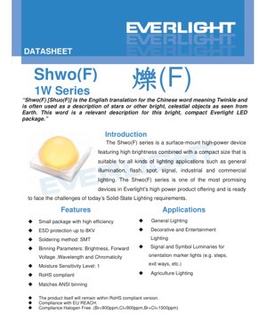
Shwo(F) series is a surface-mount high-power LED device designed to achieve high luminous flux output in a compact form factor. This product line is specifically engineered to meet the stringent demands of modern Solid-State Lighting (SSL) applications, striking an excellent balance between performance and reliability. The series name derives from a word meaning "twinkle," aptly describing its bright and focused light output, comparable to stars.
The core advantage of this series lies in the perfect combination of its small-size package and high luminous efficacy. This makes it an ideal solution for applications where space is limited but high light output is required. The device features a robust structure, integrates ESD protection, and complies with major environmental and safety standards.
1.1 Target Applications
The versatility of the Shwo(F) series enables its wide application in various lighting scenarios. Its main applications include:
- General Lighting:Providing efficient and bright light sources for daily use.
- Decorative and Entertainment Lighting:For occasions requiring the creation of aesthetic lighting effects.
- Signal and Signage Luminaires:Suitable for exit signs, step lights, and other applications requiring clear, stable illumination for guidance or safety lighting, where consistency of lighting is crucial.
- Agricultural Lighting:Supports specialized lighting requirements in horticultural and agricultural environments.
- Flash and Spotlight Illumination:Suitable for applications requiring directional, high-intensity light beams.
2. In-depth Analysis of Technical Parameters
This section provides a detailed and objective analysis of the key technical specifications that define the performance and operational limits of the Shwo(F) series LEDs.
2.1 Absolute Maximum Ratings
These ratings define the stress limits beyond which permanent damage to the device may occur. Continuous operation at or near these limits is not recommended.
- Maximum DC Forward Current (IF):The standard Shwo(F) series has a rated current of 1000mA at a heat sink pad temperature of 25°C. The "High Luminous Flux" and "Ultra High Luminous Flux" variants in the series have an increased rated current of 1500mA under the same conditions.
- Maximum Peak Pulse Current (IPulse):For pulse operation (duty cycle 1/10 @ 1kHz), the standard series can withstand 1250mA, while the high luminous flux version is rated for 1500mA.
- Maximum junction temperature (TJ):The semiconductor junction temperature must not exceed 150°C. Proper thermal management is crucial to ensure the operating temperature remains below this limit.
- Operating and Storage Temperature (TOperating, TStorage):The device's specified ambient temperature range is -40°C to +100°C.
- Thermal resistance (Rth):The key parameter of 5 °C/W indicates the temperature rise per watt of power dissipation. A lower value signifies better heat dissipation performance.
- ESD Protection (VB):The device provides electrostatic discharge protection up to 8000V (Human Body Model), enhancing robustness during handling.
- Soldering:The maximum soldering temperature allowed during reflow soldering is 260°C, and it is recommended to perform a maximum of 2 reflow cycles.
2.2 Luminous and Electrical Characteristics
The performance of the LED is characterized under specific test conditions, typically with the thermal pad temperature stabilized at 25°C.
Luminous Flux:The datasheet provides detailed minimum luminous flux binning information. For example, for Cool White LEDs driven at 350mA, the binning ranges from 130 lm (J41CX) to 175 lm (JJ1CX). Neutral White and Warm White variants have their corresponding luminous flux bins. Due to phosphor conversion efficiency, Warm White typically exhibits a slightly lower output value at the same drive current.
Forward Voltage (VF):Although not listed in the provided excerpt, the product naming convention includes a "V" code for forward voltage binning. This parameter is crucial for driver design as it determines the required supply voltage for a given current.
Karakteristik Warna:LED cahaya putih diklasifikasikan berdasarkan Correlated Color Temperature (CCT): cahaya putih dingin (4745-7050K), cahaya putih netral (3710-4745K), dan cahaya putih hangat (2580-3710K). Kutipan yang diberikan juga menyebutkan biru safir (445-460nm) sebagai pilihan LED berwarna. Binning kromatis memastikan konsistensi warna dalam rentang yang ditentukan pada diagram kromatisitas CIE.
2.3 Thermal Management
Effective thermal management is crucial for the performance and lifespan of LEDs. A thermal resistance rating of 5 °C/W indicates the efficiency of heat transfer from the LED junction to the thermal pad. To maintain a safe junction temperature, the thermal path from this pad to the ambient environment (through the PCB and any potential heat sinks) must be designed with low thermal impedance. Exceeding the maximum junction temperature will accelerate lumen depreciation and may lead to catastrophic failure.
3. Grading System Description
The Shwo(F) series employs a comprehensive binning structure to ensure end-users receive consistent performance and color. Binning is the grouping of LEDs based on specific measured parameters.
3.1 Luminous Flux Binning
LEDs are binned according to their minimum light output at the standard test current (350mA). The bin code (e.g., JJ, J8, JH for cool white) directly corresponds to a guaranteed minimum luminous flux value in lumens. This allows designers to select the required brightness level for their application with certainty.
3.2 Color/Chromaticity Binning
For white LEDs, the primary binning criterion is the Correlated Color Temperature (CCT), as defined in the "Color Options" table (C, N, M). Within each CCT range, further chromaticity binning (the "1234" code in the model number) ensures that the emitted white light falls within a tightly controlled region on the chromaticity diagram, thereby minimizing visible color differences between individual LEDs within a luminaire.
3.3 Forward Voltage Binning
LEDs are also binned according to their forward voltage drop at a specified current. This is indicated by the "V" code in the model number. By VFGrouping LEDs in this way helps in designing more efficient and consistent drive circuits, especially when multiple LEDs are connected in series.
4. Performance Curve Analysis
Graphical data is crucial for understanding device behavior under actual conditions, although the excerpt does not fully elaborate.
4.1 Typical Light Output vs. Thermal Pad Temperature
The light output of an LED decreases as the temperature of the thermal pad (and thus the junction temperature) increases. The derating curve typically shows the relative luminous flux dropping from 100% at 25°C to a lower percentage at high temperatures (e.g., 85°C). This curve is essential for calculating the actual light output in applications where the LED cannot be maintained at 25°C.
4.2 Typical Relative Luminous Flux vs. Forward Current
This curve shows how light output varies with drive current. While output generally increases with current, the relationship is not perfectly linear, and lumens-per-watt efficiency typically decreases at higher currents due to increased thermal load and efficiency droop effects. The datasheet provides this graph to help designers optimize the trade-off between brightness and efficacy.
4.3 Current Derating Curve
To prevent overheating, the maximum allowable forward current must be reduced as the ambient temperature or the temperature of the thermal pad increases. The derating curve specifies the safe operating current at temperatures above 25°C, ensuring that the maximum junction temperature is never exceeded.
5. Mechanical and Packaging Information
5.1 Pad Configuration
The device uses a surface-mount technology (SMT) pad layout. Although the excerpt does not include specific dimensional drawings, the pad configuration is a critical part of the datasheet. It defines the package dimensions for PCB design, including the location and size of the electrical connection pads, as well as the crucial, large-area thermal pad used to transfer heat from the LED chip to the printed circuit board.
5.2 Polarity Marking
SMT LED must have a clear polarity mark (typically the cathode mark) on the package or in the package dimension drawing to ensure correct orientation during assembly. Incorrect polarity will cause the device to fail to illuminate.
5.3 Device Packaging
LEDs are supplied in tape-and-reel packaging suitable for automatic placement machines. The "P" code in the model number indicates "Tape and Reel" packaging. This form protects the devices and ensures efficient handling during high-volume manufacturing.
6. Soldering and Assembly Guide
6.1 Reflow Soldering Parameters
The maximum soldering temperature rating of the device is 260°C, and it can withstand up to two reflow soldering cycles. The standard lead-free reflow soldering profile (with a peak temperature typically between 240-260°C) is applicable. When developing the reflow soldering profile, the thermal capacity of the package, especially that of the thermal pad, must be considered to ensure proper reflow of all solder joints.
6.2 Humidity Sensitivity
According to JEDEC standards, the Moisture Sensitivity Level (MSL) for the Shwo(F) series is Level 1. This is the most robust level, indicating unlimited floor life at ≤30°C/85% RH. If the packaging seal remains intact, no baking is required before use. This simplifies storage and handling logistics.
6.3 Storage Conditions
Recommended storage temperature is -40°C to +100°C. Although MSL Level 1 requirements are lenient, it is still good practice to store components in a dry, controlled environment to prevent any potential contamination or degradation.
7. Ordering Information and Product Label
7.1 Model Naming Rules
The model follows a detailed structure: ELSWF–ABCDE–FGHIJ–V1234. Each segment conveys specific information:
- AB:Minimum luminous flux or radiant power code.
- C:Radiation pattern (e.g., "1" indicates Lambertian type).
- D:Color code (C, N, M, L).
- E:Recommended operating power ("1" indicates 1W).
- H:Packaging type ("P" indicates tape and reel).
- V:Forward voltage binning.
- 1234:Color chromaticity or CCT binning.
7.2 Product Label
Reel and tape packaging will include labels printed with the full model number, quantity, date code, and other traceability information to ensure correct material handling and inventory control.
8. Application Design Considerations
8.1 Drive Selection
The drive power LED must use a constant current driver. The current output of the driver must match the intended operating point of the LED (e.g., 350mA, 700mA, or the maximum rated current). The voltage adaptation range of the driver must be sufficiently large to accommodate the sum of the forward voltages of all LEDs in the series circuit, while also considering the voltage bin (V code) and the effect of temperature on VF.
8.2 Thermal Design
This is the most critical aspect in high-power LED design. The PCB must be designed as a heat sink. This includes:
- Using a PCB with sufficient copper thickness (e.g., 2 ounces).
- Designing large-area copper pour regions, connected to the LED's thermal pad via multiple thermal vias.
- For high-power applications, it may be necessary to connect the PCB to an external aluminum heat sink.
- Use thermal interface material to minimize thermal resistance between layers.
8.3 Optical Design
The Lambertian radiation pattern provides a wide, uniform viewing angle. For applications requiring a focused beam, secondary optical elements (lenses or reflectors) must be used. The small form factor package of the Shwo(F) series allows for compact optical assembly design.
9. Compliance and Environmental Standards
The design of this product complies with several key international standards:
- RoHS (Restriction of Hazardous Substances):The device contains no lead, mercury, cadmium, or other restricted substances.
- Halogen-free:符合对溴(Br<900ppm)、氯(Cl<900ppm)及其总和(Br+Cl<1500ppm)的严格限制。
- EU REACH:Compliance with the Registration, Evaluation, Authorisation and Restriction of Chemicals regulation.
10. Reliability and Service Life
Although the excerpt does not provide specific L70 or L90 life data (the time when light output drops to 70% or 90% of its initial value), the lifetime of an LED is directly related to its operating conditions. The primary factor is junction temperature. Operating the LED well within its maximum ratings, particularly maintaining a low junction temperature through effective thermal management, is the most important measure to ensure a long operating life and slow lumen depreciation. The rated maximum junction temperature of 150°C is a limit, not a target; for reliability, the lower the junction temperature, the better.
11. Technical Comparison and Differentiation
The Shwo(F) series positions itself in the competitive landscape of SMT high-power LEDs through the following key attributes:
- High Brightness in a Compact Size:It offers excellent lumens per unit package area ratio.
- Robust ESD Protection:8kV HBM protection enhances durability during handling and assembly compared to devices with lower or no protection rating.
- Comprehensive Binning:Detailed luminous flux, voltage, and chromaticity binning provide designers with a high degree of predictability and consistency.
- Favorable Moisture Sensitivity:MSL Level 1 rating provides significant logistics and storage advantages compared to higher MSL grade components that require dry packaging and baking.
- Extensive Compliance:Out-of-the-box compliance with RoHS, halogen-free, and REACH standards simplifies the compliance process for end-product manufacturers.
12. Frequently Asked Questions (Based on Technical Parameters)
Q: Can I drive this LED with a constant voltage source?
A: No. LEDs are current-driven devices. A constant voltage power supply cannot regulate current, which can lead to thermal runaway and damage the LED. Always use a constant current drivers.
Q: The datasheet shows performance at 25°C. What output can I expect at 60°C?
A: You must refer to the "Typical Luminous Output vs. Thermal Pad Temperature" curve. Luminous output decreases with increasing temperature. At 60°C, the relative luminous flux will be a percentage of the 25°C value (e.g., approximately 85-90%). Your thermal design must account for this derating.
Q: What are the differences between the Standard, High Luminous Flux, and Ultra-High Luminous Flux series?
A: The main differences are the maximum allowable drive current (1000mA vs. 1500mA) and the corresponding higher available luminous flux bins. The High Luminous Flux versions may utilize more advanced chip technology or packaging to handle the higher power density.
Q: Is a heatsink always required?
A: It depends on the drive current and application environment. At full rated current (1000mA/1500mA), a dedicated heatsink is almost certainly required. At lower currents (e.g., 350mA) and with good PCB thermal design, a separate heatsink may not be necessary, but careful thermal analysis is still required.
13. Practical Design and Usage Examples
Example 1: Exit Sign Luminaires
An engineer is designing a slim, energy-efficient exit sign. He selects a neutral white Shwo(F) LED (e.g., ELSWF-J71NX-...), driven at 350mA, to achieve the required brightness while maintaining high luminous efficacy. The compact SMT package allows for a very thin light source module. The MSL Level 1 rating simplifies the assembly process at his factory. He designs a two-layer PCB where a large-area copper pour on the bottom layer is connected to the LED's thermal pad via a set of vias, ensuring the junction temperature remains low for long-term reliability.
Example 2: High-Bay Industrial Lighting
For a high-output industrial luminaire, the designer selected the ultra-high luminous flux series variant, driven at 1200mA. Multiple LEDs are arranged on a Metal Core Printed Circuit Board (MCPCB), which is then attached to a large aluminum profile heatsink. The chosen driver provides a constant 1200mA current, with a voltage range sufficiently high to power 12 LEDs connected in series. It is specified in detail that the chromaticity binning ("1234" code) for all procured LEDs must be identical to ensure the luminaire emits uniform white light without visible color differences.
14. Introduction to Working Principles
A Light Emitting Diode (LED) is a semiconductor device that emits light through electroluminescence. When a forward voltage is applied across the p-n junction, electrons and holes recombine within the semiconductor material, releasing energy in the form of photons. The wavelength (color) of the emitted light is determined by the energy band gap of the semiconductor material. For white LEDs like the Shwo(F) series, a blue LED chip is coated with a phosphor layer. Part of the blue light is converted by the phosphor into light of longer wavelengths (yellow, red), and the mixture of blue and converted light is perceived by the human eye as white light. The specific formulation of the phosphor determines the white light's Correlated Color Temperature (CCT).
15. Teknoloji Trendleri ve Gelişmeler
Katı Hal Aydınlatma endüstrisi, Shwo(F) serisi gibi bileşenlerle ilgili birkaç önemli yörünge boyunca gelişmeye devam etmektedir:
- Işık Verimliliğinin Artırılması (lümen/vat):LED chip design, phosphor technology, and packaging efficiency continue to improve, driving higher light output under the same electrical input power.
- Higher power density:Packaging is becoming capable of handling higher drive currents and dissipating more heat from smaller sizes, as seen in "high luminous flux" and "ultra-high luminous flux" variants.
- Improved color quality and consistency:Stricter chromaticity binning, and phosphors developed for high Color Rendering Index (CRI) and specific spectral power distributions (e.g., for horticulture).
- Enhanced reliability and robustness:Improvements in materials and packaging technology to withstand higher temperatures and harsher environmental conditions, extending operational lifetime.
- Integration and Intelligent Functions:Although this discrete component does not possess them, the broader trend includes integrating LEDs with drivers, sensors, and communication interfaces for intelligent lighting systems.
Detailed Explanation of LED Specification Terminology
Complete Interpretation of LED Technical Terminology
I. Core Indicators of Photoelectric Performance
| Terminology | Unit/Representation | Popular Explanation | Me ya sa yake da muhimmanci |
|---|---|---|---|
| Tasirin haske (Luminous Efficacy) | lm/W (lumens per watt) | The luminous flux emitted per watt of electrical power, higher values indicate greater energy efficiency. | It directly determines the energy efficiency rating of the luminaire and the electricity cost. |
| Luminous Flux | lm (lumen) | The total amount of light emitted by a light source, commonly known as "brightness". | Determines whether a luminaire is bright enough. |
| Viewing Angle | ° (degree), e.g., 120° | The angle at which luminous intensity drops to half, determining the beam width. | Affects the range and uniformity of illumination. |
| Color Temperature (CCT) | K (Kelvin), such as 2700K/6500K | Launin haske mai dumi ko sanyi, ƙananan ƙima suna karkata zuwa rawaya/dumi, manyan ƙima suna karkata zuwa fari/sanyi. | Yana ƙayyade yanayin hasken wuta da kuma yanayin da ya dace. |
| Color Rendering Index (CRI / Ra) | Unitless, 0–100 | The ability of a light source to reproduce the true colors of objects, with Ra≥80 being preferable. | Affects color authenticity, used in high-demand places such as shopping malls and art galleries. |
| Color tolerance (SDCM) | MacAdam ellipse step, such as "5-step" | A quantitative metric for color consistency; a smaller step number indicates better color consistency. | Ensure no color variation among luminaires from the same batch. |
| Dominant Wavelength | nm (nanometer), e.g., 620nm (red) | Wavelength values corresponding to the colors of colored LEDs. | Determines the hue of monochromatic LEDs such as red, yellow, and green. |
| Spectral Distribution | Wavelength vs. Intensity Curve | Shows the intensity distribution of light emitted by an LED at each wavelength. | Affects color rendering and color quality. |
II. Electrical Parameters
| Terminology | Symbol | Popular Explanation | Design Considerations |
|---|---|---|---|
| Forward Voltage | Vf | The minimum voltage required to light up an LED, similar to a "starting threshold". | The driving power supply voltage must be ≥ Vf; the voltages add up when multiple LEDs are connected in series. |
| Forward Current | If | The current value that makes the LED emit light normally. | Constant current drive is often used, as the current determines brightness and lifespan. |
| Maximum Pulse Current | Ifp | The peak current that can be withstood for a short period of time, used for dimming or flashing. | Pulse width and duty cycle must be strictly controlled, otherwise overheating damage will occur. |
| Reverse Voltage | Vr | Maximum reverse voltage that an LED can withstand; exceeding it may cause breakdown. | Reverse connection or voltage surges must be prevented in the circuit. |
| Thermal Resistance (Thermal Resistance) | Rth (°C/W) | The resistance to heat flow from the chip to the solder joint. A lower value indicates better heat dissipation. | High thermal resistance requires stronger heat dissipation design, otherwise junction temperature rises. |
| Electrostatic Discharge Immunity (ESD Immunity) | V (HBM), e.g., 1000V | Electrostatic discharge immunity; a higher value indicates greater resistance to electrostatic damage. | Anti-static measures must be implemented during production, especially for high-sensitivity LEDs. |
III. Thermal Management and Reliability
| Terminology | Key Indicators | Popular Explanation | Impact |
|---|---|---|---|
| Junction Temperature | Tj (°C) | The actual operating temperature inside the LED chip. | For every 10°C reduction, the lifespan may double; excessively high temperatures cause lumen depreciation and color shift. |
| Lumen Depreciation | L70 / L80 (hours) | The time required for the brightness to drop to 70% or 80% of its initial value. | Directly define the "useful life" of an LED. |
| Lumen Maintenance | % (e.g., 70%) | The percentage of remaining brightness after a period of use. | Characterizes the ability to maintain brightness after long-term use. |
| Color Shift | Δu′v′ or MacAdam ellipse | The degree of color change during use. | Affects the color consistency of the lighting scene. |
| Thermal Aging | Material performance degradation | Degradation of packaging materials due to prolonged high temperatures. | Zai iya haifar da raguwar haske, canjin launi ko gazawar bude hanya. |
IV. Kullewa da Kayan aiki
| Terminology | Nau'o'in gama gari | Popular Explanation | Characteristics and Applications |
|---|---|---|---|
| Package Types | EMC, PPA, Ceramics | The housing material that protects the chip and provides optical and thermal interfaces. | EMC offers good heat resistance and low cost; ceramics provide superior heat dissipation and long lifespan. |
| Chip Structure | Front-side, Flip Chip | Chip electrode arrangement method. | Flip-chip offers better heat dissipation and higher luminous efficacy, suitable for high-power applications. |
| Phosphor coating. | YAG, silicate, nitride | Coated on the blue LED chip, partially converted to yellow/red light, mixed to form white light. | Different phosphors affect luminous efficacy, color temperature, and color rendering. |
| Lens/Optical Design | Flat, microlens, total internal reflection | Optical structure on the packaging surface, controlling light distribution. | Determines the emission angle and light distribution curve. |
V. Quality Control and Grading
| Terminology | Grading Content | Popular Explanation | Purpose |
|---|---|---|---|
| Luminous Flux Binning | Codes such as 2G, 2H | Group by brightness level, each group has a minimum/maximum lumen value. | Ensure consistent brightness for products in the same batch. |
| Voltage binning | Code such as 6W, 6X | Grouped by forward voltage range. | Ease of matching the drive power supply, improving system efficiency. |
| Color binning | 5-step MacAdam ellipse | Group by color coordinates to ensure colors fall within a minimal range. | Ensure color consistency to avoid uneven color within the same luminaire. |
| Color temperature grading | 2700K, 3000K, etc. | Group by color temperature, each group has a corresponding coordinate range. | Meet the color temperature requirements of different scenarios. |
VI. Testing and Certification
| Terminology | Standard/Test | Popular Explanation | Meaning |
|---|---|---|---|
| LM-80 | Lumen Maintenance Test | Long-term operation under constant temperature conditions, recording data on luminance attenuation. | For estimating LED lifetime (in conjunction with TM-21). |
| TM-21 | Lifetime projection standard | Estimating lifespan under actual usage conditions based on LM-80 data. | Providing scientific life prediction. |
| IESNA Standard | Illuminating Engineering Society Standard | Covers optical, electrical, and thermal test methods. | Industry-recognized testing basis. |
| RoHS / REACH | Environmental Certification | Ensure the product does not contain harmful substances (e.g., lead, mercury). | Entry requirements for the international market. |
| ENERGY STAR / DLC | Energy efficiency certification | Energy efficiency and performance certification for lighting products. | Commonly used in government procurement and subsidy programs to enhance market competitiveness. |