Table of Contents
- 1. Product Overview
- 2. Technical Parameter Deep Dive
- 2.1 Absolute Maximum Ratings
- 2.2 Electro-Optical Characteristics
- 3. Binning System Explanation
- 3.1 Luminous Intensity Binning (CAT Code)
- 3.2 Dominant Wavelength Binning (HUE Code - Group A)
- 3.3 Forward Voltage Binning (REF Code - Group N)
- 4. Performance Curve Analysis
- 4.1 Forward Current vs. Forward Voltage (I-V Curve)
- 4.2 Relative Luminous Intensity vs. Forward Current
- 4.3 Relative Luminous Intensity vs. Ambient Temperature
- 4.4 Spectrum Distribution
- 4.5 Radiation Pattern
- 4.6 Forward Current Derating Curve
- 5. Mechanical and Package Information
- 5.1 Package Dimensions (P-LCC-2)
- 5.2 Polarity Identification
- 5.3 Recommended PCB Footprint
- 6. Soldering and Assembly Guidelines
- 6.1 Reflow Soldering Profile
- 6.2 Hand Soldering
- 6.3 Moisture Sensitivity and Storage
- 7. Packaging and Ordering Information
- 7.1 Tape and Reel Specifications
- 7.2 Label Information
- 8. Application Suggestions
- 8.1 Typical Application Scenarios
- 8.2 Light Pipe Design Considerations
- 8.3 Circuit Design Notes
- 9. Technical Comparison and Differentiation
- 10. Frequently Asked Questions (Based on Technical Parameters)
- 10.1 What resistor value should I use with a 5V supply?
- 10.2 Can I drive this LED with a 3.3V supply?
- 10.3 Why does the luminous intensity have such a wide range (225-565 mcd)?
- 10.4 Yaya zafi ke shafi aiki?
- 11. Zane na Aiki da Misalin Amfani
- 11.1 Designing a Multi-LED Status Indicator Panel
- 12. Operating Principle Introduction
- 13. Technology Trends and Context
1. Product Overview
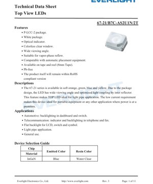
The 67-21 series represents a family of Top View LEDs housed in a compact P-LCC-2 surface-mount package. This series is engineered to deliver reliable performance as an optical indicator across a diverse range of electronic applications. The device features a colorless clear window and a white package body, which contributes to its optical efficiency and aesthetic versatility.
The core design philosophy centers on providing a wide viewing angle, achieved through an optimized package geometry and an internal reflector. This characteristic makes the LED particularly suitable for applications employing light pipes, where uniform light distribution is critical. Furthermore, the device operates at low current levels, making it an excellent choice for power-sensitive applications such as portable and battery-operated equipment.
The series is available in multiple emitted colors including soft orange, green, blue, and yellow, with the specific model detailed in this document being a blue LED utilizing an InGaN chip. It is fully compatible with automated pick-and-place equipment and standard vapor-phase reflow soldering processes, supporting high-volume manufacturing. The product is Pb-free and conforms to RoHS compliance standards.
2. Technical Parameter Deep Dive
2.1 Absolute Maximum Ratings
These ratings define the stress limits beyond which permanent damage to the device may occur. Operation under or at these limits is not guaranteed and should be avoided in circuit design.
- Reverse Voltage (VR): 5 V. Exceeding this voltage in reverse bias can cause junction breakdown.
- Continuous Forward Current (IF): 30 mA. The maximum DC current that can be applied continuously.
- Peak Forward Current (IFP): 100 mA. This is permissible only under pulsed conditions with a duty cycle of 1/10 at 1 kHz.
- Power Dissipation (Pd): 110 mW. The maximum power the package can dissipate, calculated as VF * IF.
- Electrostatic Discharge (ESD) HBM: 1000 V. The device's sensitivity to electrostatic discharge; proper handling procedures are required.
- Operating Temperature (Topr): -40°C to +85°C. The ambient temperature range for reliable operation.
- Storage Temperature (Tstg): -40°C to +90°C.
- Soldering Temperature: The device can withstand reflow soldering with a peak temperature of 260°C for 10 seconds, or hand soldering at 350°C for 3 seconds.
2.2 Electro-Optical Characteristics
These parameters are measured at a standard test condition of an ambient temperature (Ta) of 25°C and a forward current (IF) of 20 mA, unless otherwise specified. Tolerances are applied as noted.
- Luminous Intensity (Iv): Ranges from a minimum of 225 mcd to a maximum of 565 mcd, with a typical tolerance of ±11%. This defines the perceived brightness of the LED.
- Viewing Angle (2θ1/2): 120 degrees (typical). This is the full angle at which the luminous intensity drops to half of its peak value, indicating a very wide emission pattern.
- Peak Wavelength (λP): 468 nm (typical). The wavelength at which the spectral power distribution is maximum.
- Dominant Wavelength (λd): Ranges from 464.5 nm to 476.5 nm, with a tolerance of ±1 nm. This wavelength corresponds to the perceived color of the light.
- Spectral Bandwidth (Δλ): 25 nm (typical). The width of the emitted spectrum at half its maximum power.
- Forward Voltage (VF): Ranges from 2.70 V to 3.70 V at 20 mA, with a tolerance of ±0.1 V. This is the voltage drop across the LED when conducting.
- Reverse Current (IR): Maximum of 50 μA at a reverse voltage of 5V.
3. Binning System Explanation
To ensure consistency in brightness, color, and electrical characteristics, the LEDs are sorted into bins. The specific device code (e.g., /B7C-AS2U1N/2T) incorporates these bin codes.
3.1 Luminous Intensity Binning (CAT Code)
LEDs are grouped based on their measured luminous intensity at 20 mA.
- S2: 225 - 285 mcd
- T1: 285 - 360 mcd
- T2: 360 - 450 mcd
- U1: 450 - 565 mcd
3.2 Dominant Wavelength Binning (HUE Code - Group A)
For blue LEDs, the dominant wavelength is binned as follows:
- A9: 464.5 - 467.5 nm
- A10: 467.5 - 470.5 nm
- A11: 470.5 - 473.5 nm
- A12: 473.5 - 476.5 nm
3.3 Forward Voltage Binning (REF Code - Group N)
LEDs are also binned by their forward voltage drop at 20 mA.
- 10: 2.70 - 2.90 V
- 11: 2.90 - 3.10 V
- 12: 3.10 - 3.30 V
- 13: 3.30 - 3.50 V
- 14: 3.50 - 3.70 V
4. Performance Curve Analysis
The typical characteristic graphs provide insight into the LED's behavior under varying conditions.
4.1 Forward Current vs. Forward Voltage (I-V Curve)
The graph shows a non-linear relationship, typical of a diode. The forward voltage increases with current, starting around 2.6V at very low current and reaching approximately 3.4V at 20mA. This curve is essential for designing the current-limiting circuitry.
4.2 Relative Luminous Intensity vs. Forward Current
Luminous intensity increases with forward current but not linearly. The curve tends to roll off at higher currents due to increased junction temperature and efficiency droop. This highlights the importance of driving the LED at or near its recommended current (20mA) for optimal efficiency.
4.3 Relative Luminous Intensity vs. Ambient Temperature
The light output decreases as the ambient temperature rises. The graph shows that at the maximum operating temperature of +85°C, the output may be significantly lower than at 25°C. This thermal derating must be accounted for in applications with high ambient temperatures.
4.4 Spectrum Distribution
The spectral plot confirms a blue emission with a peak around 468nm and a typical bandwidth of 25nm. The spectrum is monochromatic, as expected from an InGaN-based blue LED.
4.5 Radiation Pattern
The polar diagram visually confirms the wide 120° viewing angle, showing a Lambertian-like emission pattern where intensity is fairly uniform across a broad angle before falling off.
4.6 Forward Current Derating Curve
This curve dictates the maximum allowable continuous forward current as a function of ambient temperature. As temperature increases, the maximum safe current decreases to prevent exceeding the 110mW power dissipation limit and to ensure long-term reliability.
5. Mechanical and Package Information
5.1 Package Dimensions (P-LCC-2)
LED yana cikin fakitin da ake hawa a saman. Ma'auni mafi muhimmanci sun haɗa da girman jiki, tazarar jagora, da tsayin gaba ɗaya. Duk ƙayyadaddun da ba a bayyana ba ±0.1mm ne. An ƙera fakitin don kwanciyar hankali yayin sayar da reflow da dacewa da madaidaicin kaset ɗin 8mm.
5.2 Polarity Identification
Ana gano cathode yawanci ta hanyar alamar gani akan fakitin, kamar tsaga, ɗigo, ko koren launi a gefen cathode na rami na guntu. Dole ne a kiyaye polarity daidai yayin haɗawa don hana lalacewar karkatar da baya.
5.3 Recommended PCB Footprint
A land pattern design that accommodates the package dimensions and allows for proper solder fillet formation is recommended. The footprint should align with the package's thermal pad (if present) and electrical pads to ensure reliable mechanical and electrical connection.
6. Soldering and Assembly Guidelines
6.1 Reflow Soldering Profile
The device is suitable for vapor-phase and infrared reflow soldering. A standard lead-free profile with a peak temperature not exceeding 260°C for a duration of 10 seconds is specified. The time above liquidus (e.g., 217°C) should be controlled to minimize thermal stress on the component.
6.2 Hand Soldering
If hand soldering is necessary, the iron tip temperature should be limited to 350°C, and the contact time per lead should not exceed 3 seconds. Use a low-power iron and avoid applying mechanical stress to the package.
6.3 Moisture Sensitivity and Storage
The LEDs are packaged in moisture-resistant barrier bags with desiccant to prevent moisture absorption, which can cause "popcorning" during reflow. Once the sealed bag is opened, the components should be used within a specified time frame (e.g., 168 hours at <30°C/60%RH) or rebaked according to standard IPC/JEDEC guidelines.
7. Packaging and Ordering Information
7.1 Tape and Reel Specifications
Ana kayan suna isar da su a kan tef ɗin ɗaukar kaya mai faɗin milimita 8 da aka zana. Girman reel da tazarar aljihu an daidaita su don dacewa da na'urorin ciyarwa ta atomatik. Ƙididdiga na yau da kullun na kaya shine guda 2000 a kowace reel, tare da mafi ƙarancin adadin oda na 250, 500, 1000, ko guda 2000 da ake samu.
7.2 Label Information
The reel label contains critical information for traceability and identification, including: Part Number (PN), Customer Part Number (CPN), Quantity (QTY), Lot Number, and the specific Binning Codes for Luminous Intensity (CAT), Dominant Wavelength (HUE), and Forward Voltage (REF).
8. Application Suggestions
8.1 Typical Application Scenarios
- Automotive Electronics: Backlighting for dashboard instruments, switches, and control panels.
- Telecommunication Equipment: Status indicators and keypad backlighting in telephones, fax machines, and networking hardware.
- Consumer Electronics: Power/status indicators, backlighting for LCD displays, symbols, and membrane switches in appliances, audio/video equipment, and computing peripherals.
- General Indication: Any application requiring a bright, reliable, low-power status indicator.
8.2 Light Pipe Design Considerations
The wide 120° viewing angle is a key asset for light pipe applications. For optimal coupling efficiency:
- Position the LED as close as possible to the entrance of the light pipe.
- Ensure the light pipe material has high transmittance and is designed to guide and disperse light effectively.
- Consider the LED's radiation pattern when designing the pipe's input surface geometry.
8.3 Circuit Design Notes
- Always use a series current-limiting resistor. Calculate its value based on the supply voltage (VCC), the LED's forward voltage (VF - use max value for reliability), and the desired forward current (IF). Formula: R = (VCC - VF) / IF.
- For constant brightness across a range of supply voltages or temperatures, consider using a constant current driver instead of a simple resistor.
- Observe the absolute maximum ratings, especially for reverse voltage. Incorporate protection (e.g., a parallel diode in reverse polarity) if the circuit is prone to voltage spikes or reverse connection.
9. Technical Comparison and Differentiation
The 67-21 series differentiates itself in the market of SMD indicator LEDs through several key features:
- Superior Viewing Angle: The 120° viewing angle is notably wider than many standard SMD LEDs (which may be 60-80°), providing more uniform visibility from off-axis perspectives, crucial for panel indicators.
- Optimized for Light Pipes: The package design with an internal reflector is specifically tuned to couple light efficiently into light guides, a common requirement in modern industrial and consumer product design.
- Low Current Operation: Its specification at 20mA (with good brightness) makes it more energy-efficient compared to LEDs requiring higher drive currents for similar output, benefiting battery life.
- Robust Binning: The detailed binning system for intensity, wavelength, and voltage allows designers to select parts with tight performance tolerances, ensuring consistency in end products, especially in multi-LED arrays.
10. Frequently Asked Questions (Based on Technical Parameters)
10.1 What resistor value should I use with a 5V supply?
Using the maximum VF of 3.7V for a conservative design and a target IF of 20mA: R = (5V - 3.7V) / 0.02A = 65 Ohms. The nearest standard value is 68 Ohms. Recalculating: IF = (5V - 3.7V) / 68Ω ≈ 19.1 mA, which is safe and within specification. Always verify actual current in the circuit.
10.2 Can I drive this LED with a 3.3V supply?
Yes, but careful calculation is needed. Using a typical VF of 3.2V: R = (3.3V - 3.2V) / 0.02A = 5 Ohms. This very low resistance value makes the current highly sensitive to variations in VF and VCC. A slight drop in VCC or increase in VF could extinguish the LED. Using a constant current driver is strongly recommended for low headroom voltage situations.
10.3 Why does the luminous intensity have such a wide range (225-565 mcd)?
This is the total possible range across the entire product series and all bins. Individual LEDs are binned into specific groups (S2, T1, T2, U1). When ordering, you specify the desired intensity bin (e.g., U1 for highest brightness) to get a much tighter range (450-565 mcd). This allows for cost optimization and performance matching.
10.4 Yaya zafi ke shafi aiki?
As shown in the performance curves, increasing ambient temperature reduces light output (efficiency droop) and increases the forward voltage slightly. At high temperatures, the maximum allowable continuous current also decreases. For applications operating at high ambient temperatures (e.g., inside an automotive dashboard), design should be based on performance data at the expected operating temperature, not just at 25°C.
11. Zane na Aiki da Misalin Amfani
11.1 Designing a Multi-LED Status Indicator Panel
Scenario: A control panel requires 10 blue status indicators. Uniform brightness and color are critical for user experience.
Implementation:
- Binning Selection: Specify the same intensity bin (e.g., T2: 360-450 mcd) and dominant wavelength bin (e.g., A10: 467.5-470.5 nm) for all 10 LEDs to ensure visual consistency.
- Circuit Design: Use a 12V supply. To drive 10 LEDs in parallel with individual resistors: Calculate resistor for max VF=3.7V, IF=20mA. R = (12V - 3.7V) / 0.02A = 415 Ohms. Use 430 Ohms (standard value). Power per resistor: P = I2R = (0.02)2 * 430 = 0.172W. Use 1/4W resistors. Total current from supply: 10 * 20mA = 200mA.
- PCB Layout: Sanya LEDs tare da daidaitaccen alkibla. Tabbatar da alamar cathode akan silkscreen na PCB ta dace da kunshin LED. Bayar da isasshen jan karfe don ginshiƙan wutar lantarki na gama gari masu ɗaukar 200mA.
- Jagorar Haske: Idan ana amfani da bututun haske, ƙirƙira ƙofar bututu don ɗaukar mazugi na fitar da haske na LED na 120°. Yi amfani da PC na matakin gani ko acrylic.
12. Operating Principle Introduction
The 67-21 series LED is a solid-state light source based on a semiconductor p-n junction. The active region utilizes an Indium Gallium Nitride (InGaN) compound semiconductor material, which is epitaxially grown on a substrate. When a forward voltage exceeding the diode's threshold is applied, electrons and holes are injected into the active region where they recombine. In a direct bandgap semiconductor like InGaN, this recombination event releases energy in the form of photons (light). The specific wavelength (color) of the emitted light, in this case blue (~468 nm), is determined by the bandgap energy of the InGaN material, which can be tuned by varying the indium content during crystal growth. The generated light is then extracted through the package's colorless clear epoxy dome, which also acts as a lens, and the internal reflector helps direct the light into a wide emission pattern.
13. Technology Trends and Context
LEDs in P-LCC and similar surface-mount packages represent the mainstream for indicator applications, having largely replaced through-hole LEDs in modern electronics due to their compatibility with automated assembly and smaller footprint. The trend within this segment is towards:
- Higher Efficiency: Improving lumen-per-watt output, allowing for adequate brightness at even lower drive currents, further reducing power consumption.
- Miniaturization: Continued reduction in package size (e.g., from 0603 to 0402 metric) while maintaining or improving optical performance.
- Enhanced Optical Control: More sophisticated package designs with integrated lenses, reflectors, and diffusers to produce specific beam patterns (ultra-wide, side-view, focused) directly from the package, reducing the need for secondary optics.
- Broader Color Gamut and Stability: Tighter binning tolerances and improved phosphor technology (for white LEDs) ensure consistent color points across production batches and over the device's lifetime.
- Improved Reliability and Robustness: Enhanced materials and packaging techniques to withstand higher soldering temperatures, harsher environmental conditions, and provide better ESD protection.
The 67-21 series, with its focus on wide viewing angle and light pipe compatibility, aligns well with the trend of integrating discreet indicators into sleek, modern product designs where the light source itself is often hidden from direct view.
LED Specification Terminology
Complete explanation of LED technical terms
Photoelectric Performance
| Term | Unit/Representation | Simple Explanation | Why Important |
|---|---|---|---|
| Luminous Efficacy | lm/W (lumens per watt) | Light output per watt of electricity, higher means more energy efficient. | Directly determines energy efficiency grade and electricity cost. |
| Luminous Flux | lm (lumens) | Total light emitted by source, commonly called "brightness". | Determines if the light is bright enough. |
| Viewing Angle | ° (degrees), e.g., 120° | Angle where light intensity drops to half, determines beam width. | Affects illumination range and uniformity. |
| CCT (Color Temperature) | K (Kelvin), misal, 2700K/6500K | Moto wa mwanga, thamani ndogo huwa na rangi ya manjano/moto, thamani kubwa huwa nyeupe/baridi. | Huamua mazingira ya taa na matukio yanayofaa. |
| CRI / Ra | Unitless, 0–100 | Ability to render object colors accurately, Ra≥80 is good. | Affects color authenticity, used in high-demand places like malls, museums. |
| SDCM | MacAdam ellipse steps, e.g., "5-step" | Color consistency metric, smaller steps mean more consistent color. | Ensures uniform color across same batch of LEDs. |
| Dominant Wavelength | nm (nanometers), e.g., 620nm (red) | Wavelength corresponding to color of colored LEDs. | Determines hue of red, yellow, green monochrome LEDs. |
| Spectral Distribution | Wavelength vs intensity curve | Shows intensity distribution across wavelengths. | Affects color rendering and quality. |
Electrical Parameters
| Term | Symbol | Simple Explanation | Design Considerations |
|---|---|---|---|
| Forward Voltage | Vf | Minimum voltage to turn on LED, like "starting threshold". | Driver voltage must be ≥Vf, voltages add up for series LEDs. |
| Forward Current | If | Current value for normal LED operation. | Usually constant current drive, current determines brightness & lifespan. |
| Max Pulse Current | Ifp | Peak current tolerable for short periods, used for dimming or flashing. | Pulse width & duty cycle must be strictly controlled to avoid damage. |
| Reverse Voltage | Vr | Max reverse voltage LED can withstand, beyond may cause breakdown. | Circuit must prevent reverse connection or voltage spikes. |
| Thermal Resistance | Rth (°C/W) | Resistance to heat transfer from chip to solder, lower is better. | High thermal resistance requires stronger heat dissipation. |
| ESD Immunity | V (HBM), e.g., 1000V | Ability to withstand electrostatic discharge, higher means less vulnerable. | Anti-static measures needed in production, especially for sensitive LEDs. |
Thermal Management & Reliability
| Term | Key Metric | Simple Explanation | Impact |
|---|---|---|---|
| Junction Temperature | Tj (°C) | Actual operating temperature inside LED chip. | Every 10°C reduction may double lifespan; too high causes light decay, color shift. |
| Kupungua kwa Lumen | L70 / L80 (masaa) | Time for brightness to drop to 70% or 80% of initial. | Directly defines LED "service life". |
| Lumen Maintenance | % (e.g., 70%) | Percentage of brightness retained after time. | Indicates brightness retention over long-term use. |
| Color Shift | Δu′v′ or MacAdam ellipse | Degree of color change during use. | Affects color consistency in lighting scenes. |
| Thermal Aging | Material degradation | Deterioration due to long-term high temperature. | May cause brightness drop, color change, or open-circuit failure. |
Packaging & Materials
| Term | Common Types | Simple Explanation | Features & Applications |
|---|---|---|---|
| Package Type | EMC, PPA, Ceramic | Housing material protecting chip, providing optical/thermal interface. | EMC: yana da kyau mai jure zafi, farashi mai rahusa; Ceramic: mafi kyau zubar da zafi, tsawon rai. |
| Tsarin Chip | Gaba, Flip Chip | Chip electrode arrangement. | Flip chip: better heat dissipation, higher efficacy, for high-power. |
| Phosphor Coating | YAG, Silicate, Nitride | Covers blue chip, converts some to yellow/red, mixes to white. | Different phosphors affect efficacy, CCT, and CRI. |
| Lens/Optics | Flat, Microlens, TIR | Optical structure on surface controlling light distribution. | Determines viewing angle and light distribution curve. |
Quality Control & Binning
| Term | Binning Content | Simple Explanation | Purpose |
|---|---|---|---|
| Luminous Flux Bin | Code e.g., 2G, 2H | Grouped by brightness, each group has min/max lumen values. | Ensures uniform brightness in same batch. |
| Voltage Bin | Code e.g., 6W, 6X | Grouped by forward voltage range. | Facilitates driver matching, improves system efficiency. |
| Color Bin | 5-step MacAdam ellipse | An rarraba ta hanyar daidaitawar launi, tabbatar da kewayon matsi. | Yana ba da tabbacin daidaiton launi, ya guji rashin daidaiton launi a cikin kayan haske. |
| CCT Bin | 2700K, 3000K etc. | Grouped by CCT, each has corresponding coordinate range. | Meets different scene CCT requirements. |
Testing & Certification
| Term | Standard/Test | Simple Explanation | Significance |
|---|---|---|---|
| LM-80 | Lumen maintenance test | Long-term lighting at constant temperature, recording brightness decay. | Used to estimate LED life (with TM-21). |
| TM-21 | Standard ya kukadiria maisha | Inakadiria maisha chini ya hali halisi kulingana na data ya LM-80. | Inatoa utabiri wa kisayansi wa maisha. |
| IESNA | Illuminating Engineering Society | Covers optical, electrical, thermal test methods. | Industry-recognized test basis. |
| RoHS / REACH | Takardun muhalli | Tabbatar da babu abubuwa masu cutarwa (gubar, mercury). | Market access requirement internationally. |
| ENERGY STAR / DLC | Energy efficiency certification | Energy efficiency and performance certification for lighting. | Used in government procurement, subsidy programs, enhances competitiveness. |