Table of Contents
- 1. Product Overview
- 1.1 Core Advantages and Target Market
- 1.2 Device Selection and Variants
- 2. Technical Parameters: In-Depth Objective Interpretation
- 2.1 Absolute Maximum Ratings
- 2.2 Electro-Optical Characteristics (Ta=25°C)
- 3. Binning System Explanation
- 3.1 Luminous Intensity Binning
- 3.2 Dominant Wavelength Binning
- 4. Performance Curve Analysis
- 4.1 Forward Current vs. Forward Voltage (I-V Curve)
- 4.2 Relative Luminous Intensity vs. Forward Current
- 4.3 Relative Luminous Intensity vs. Ambient Temperature
- 4.4 Forward Current Derating Curve
- 4.5 Spectrum Distribution
- 4.6 Radiation Diagram (Polar Plot)
- 5. Mechanical and Packaging Information
- 5.1 Package Dimensions
- 5.2 Polarity Identification
- 6. Soldering and Assembly Guidelines
- 6.1 Reflow Soldering Parameters
- 6.2 Hand Soldering
- 6.3 Storage and Moisture Sensitivity
- 7. Packaging and Ordering Information
- 7.1 Tape and Reel Specifications
- 7.2 Label Explanation
- 8. Application Suggestions
- 8.1 Typical Application Scenarios
- 8.2 Critical Design Considerations
- 9. Technical Comparison and Differentiation
- 10. Frequently Asked Questions (Based on Technical Parameters)
- 10.1 Why is a series resistor required?
- 10.2 Can I drive the LED with a 3.3V supply?
- 10.3 What does the "binning" mean for my design?
- 10.4 Yaya zan fassara zanen hasken radiyo?
- 11. Practical Design and Usage Case
- 12. Principle Introduction
- 13. Development Trends
1. Product Overview
The 67-22 series represents a family of surface-mount, top-view light-emitting diodes (LEDs) designed for indicator and backlighting applications. These devices utilize a compact P-LCC-4 (Plastic Leaded Chip Carrier) package, offering a balance of performance, reliability, and ease of assembly in automated production environments.
1.1 Core Advantages and Target Market
The primary design advantages of this series include a wide viewing angle of 120 degrees, optimized light coupling facilitated by an internal reflector, and a colorless clear window. These features make the LEDs particularly well-suited for light pipe applications, where efficient light transmission and uniform illumination are critical. The low forward current requirement (typical operation at 20mA) renders these devices ideal for power-sensitive applications, such as portable consumer electronics, telecommunications equipment, and industrial control panels. The series is compliant with lead-free (Pb-free) soldering processes and RoHS directives, aligning with modern environmental and manufacturing standards.
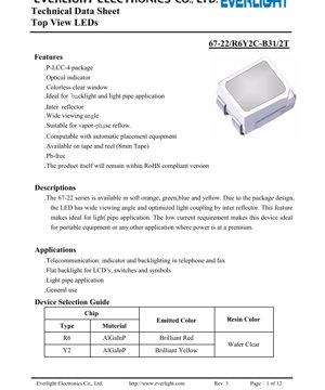
1.2 Device Selection and Variants
The series is offered in multiple emitted colors, with this datasheet detailing two specific chip types: R6 and Y2. The R6 chip, based on AlGaInP (Aluminum Gallium Indium Phosphide) material, produces a brilliant red light. The Y2 chip, also utilizing AlGaInP technology, emits a brilliant yellow light. Both variants are encapsulated in a water-clear resin, which does not alter the inherent color of the chip, ensuring high color purity and luminous intensity.
2. Technical Parameters: In-Depth Objective Interpretation
This section provides a detailed analysis of the key electrical, optical, and thermal parameters that define the operational boundaries and performance of the LED.
2.1 Absolute Maximum Ratings
These ratings specify the limits beyond which permanent damage to the device may occur. They are not intended for normal operation.
- Reverse Voltage (VR): 5V. Exceeding this voltage in reverse bias can cause junction breakdown.
- Continuous Forward Current (IF): 25mA for both R6 and Y2. This is the maximum DC current for reliable long-term operation.
- Peak Forward Current (IFP): 60mA (duty cycle 1/10, 1kHz). This rating allows for short pulses of higher current, useful for multiplexing or achieving higher instantaneous brightness.
- Power Dissipation (Pd): 60mW. This is the maximum power the package can dissipate without exceeding its thermal limits, calculated as Forward Voltage (VF) multiplied by Forward Current (IF).
- Electrostatic Discharge (ESD): 2000V (Human Body Model). This indicates a moderate level of ESD protection; proper handling procedures are still recommended.
- Operating & Storage Temperature: -40°C to +85°C and -40°C to +95°C, respectively, ensuring functionality in a wide range of environments.
2.2 Electro-Optical Characteristics (Ta=25°C)
These are the typical performance parameters under specified test conditions, usually at 20mA forward current.
- Luminous Intensity (IV): The R6 (red) variant has a typical value of 285 mcd (millicandela), while the Y2 (yellow) also reaches 285 mcd. Minimum values start from 72 mcd, with the actual delivered intensity determined by the bin code (see Section 3). A tolerance of ±11% applies.
- Viewing Angle (2θ1/2): 120 degrees. This is the full angle at which the luminous intensity drops to half of its peak value, confirming the wide-angle emission profile.
- Peak & Dominant Wavelength: For R6: Peak (λp) is 632nm, Dominant (λd) ranges from 621-631nm. For Y2: Peak is 591nm, Dominant ranges from 586-594nm. Dominant wavelength is the single-wavelength perception of color by the human eye.
- Spectrum Bandwidth (Δλ): Approximately 20nm for R6 and 15nm for Y2, indicating the spectral purity of the yellow chip is slightly higher.
- Forward Voltage (VF): For R6: 1.75V to 2.35V. For Y2: 1.8V to 2.4V (inferred from curves). The typical VF is lower for red AlGaInP LEDs compared to some other colors. A current-limiting resistor is mandatory in series to set the operating point.
- Reverse Current (IR): Maximum 10µA at VR=5V, indicating good junction quality.
3. Binning System Explanation
To ensure color and brightness consistency in production, LEDs are sorted into bins. This system allows designers to select parts that meet specific application requirements.
3.1 Luminous Intensity Binning
Dukansu R6 da Y2 guntayen an haɗa su cikin kwandon shara iri ɗaya na ƙarfi, waɗanda aka yiwa lakabi Q1, Q2, R1, R2, S1, S2. Ƙarfin haskakawa ya bambanta daga mafi ƙanƙanta 72-90 mcd (Q1) zuwa mafi girma 225-285 mcd (S2). Za a yiwa alamar lambar kwandon shara (misali, S2) akan marufi, wanda zai ba da damar zaɓar takamaiman matakin haske.
3.2 Dominant Wavelength Binning
Wannan binning yana tabbatar da daidaiton launi.
- R6 (Red): Binned into FF1 (621-626nm) and FF2 (626-631nm).
- Y2 (Yellow): Binned into DD1 (586-588nm), DD2 (588-590nm), DD3 (590-592nm), and DD4 (592-594nm).
A tighter wavelength bin (e.g., DD1 vs DD4) provides more consistent color appearance across multiple LEDs in an array.
4. Performance Curve Analysis
The datasheet provides characteristic curves that illustrate device behavior under varying conditions.
4.1 Forward Current vs. Forward Voltage (I-V Curve)
Zane-zanen ya nuna alaƙar ƙima ta yau da kullun na diode. Ƙarfin lantarki na gaba don R6 chip yana ƙaruwa daga ~1.8V zuwa ~2.2V yayin da ƙarfin lantarki ya tashi daga 1mA zuwa 30mA. Y2 chip yana nuna kewayon ƙarfin lantarki mai ɗan girma. Wannan lanƙwasa yana da mahimmanci don ƙirƙirar da'irar tuƙi da lissafin ɓarnawar wutar lantarki.
4.2 Relative Luminous Intensity vs. Forward Current
Luminous intensity increases sub-linearly with current. For both types, intensity rises sharply at low currents but the rate of increase diminishes above ~20-30mA, indicating reduced efficiency at higher drive levels. Operating at or below the recommended 20mA provides a good balance of brightness and efficiency.
4.3 Relative Luminous Intensity vs. Ambient Temperature
Luminous output decreases as ambient temperature increases. The output can drop by approximately 20-25% when the temperature rises from 25°C to 85°C. This thermal derating must be accounted for in designs where high ambient temperatures are expected, potentially requiring a lower drive current or thermal management.
4.4 Forward Current Derating Curve
This graph defines the maximum allowable continuous forward current as a function of ambient temperature. As temperature increases, the maximum permissible current decreases to prevent overheating. For example, at 85°C, the maximum current is significantly lower than the 25mA rating at 25°C.
4.5 Spectrum Distribution
The graphs display the relative radiant power versus wavelength. The R6 spectrum is centered around 632nm with a broader bandwidth. The Y2 spectrum is centered around 591nm and is narrower, confirming the data in the table.
4.6 Radiation Diagram (Polar Plot)
The polar plots visually confirm the 120-degree viewing angle. The intensity pattern is roughly Lambertian (cosine distribution), which is common for LEDs with a dome-less, planar package and an internal reflector.
5. Mechanical and Packaging Information
5.1 Package Dimensions
The P-LCC-4 package has a compact footprint. Key dimensions (in mm) are: Length: 2.0, Width: 1.25, Height: 1.1. The lead spacing is 1.0mm. A tolerance of ±0.1mm applies unless otherwise noted. Detailed drawings with all critical dimensions are provided in the datasheet for PCB land pattern design.
5.2 Polarity Identification
Kunshin yana da alamar cathode. Yawanci, wannan tsaga ce, kore kore, ko kusurwar da aka yanka a jikin kayan. Silkscreen ɗin ƙafar PCB ya kamata ya yiwa alamar kushin cathode a fili don hana sanya shi ba daidai ba.
6. Soldering and Assembly Guidelines
6.1 Reflow Soldering Parameters
The LEDs are suitable for vapor-phase or infrared reflow soldering. The recommended profile includes: Pre-heating at 150-200°C for 60-120 seconds, a time above liquidus (217°C) of 60-150 seconds, with a peak temperature not exceeding 260°C for a maximum of 10 seconds. The cooling rate should be controlled.
6.2 Hand Soldering
If hand soldering is necessary, the iron tip temperature should not exceed 350°C, and contact time should be limited to 3 seconds or less per lead to prevent thermal damage to the plastic package and the semiconductor die.
6.3 Storage and Moisture Sensitivity
The components are packaged in a moisture-resistant bag with desiccant. Before opening, they should be stored at ≤30°C and ≤90% RH. After opening the bag, the "floor life" (time components can be exposed to ambient factory conditions) is 168 hours at ≤30°C and ≤60% RH. Unused parts should be re-bagged with desiccant or stored in a dry cabinet.
7. Packaging and Ordering Information
7.1 Tape and Reel Specifications
The LEDs are supplied on 8mm wide embossed carrier tape for compatibility with automated pick-and-place equipment. The reel dimensions are standardized. Each reel contains 2000 pieces. The carrier tape dimensions (pocket size, pitch) are specified to ensure proper feeding in placement machines.
7.2 Label Explanation
The reel label contains codes for Luminous Intensity Rank (CAT), Dominant Wavelength Rank (HUE), and Forward Voltage Rank (REF). These codes correspond directly to the binning information in Sections 3.1 and 3.2, allowing traceability and precise selection.
8. Application Suggestions
8.1 Typical Application Scenarios
- Telecommunications Equipment: Status indicators, keypad backlights, and message waiting lights in phones, fax machines, and modems.
- Consumer Electronics: Power, battery, and function indicators in portable devices, audio/video equipment, and home appliances.
- Industrial & Automotive: Panel indicators, switch illumination, and fault signaling where wide viewing angle is beneficial.
- Light Pipe Applications: The internal reflector and wide angle make this series an excellent choice for coupling light into acrylic or polycarbonate light guides to remotely indicate status or backlight symbols.
8.2 Critical Design Considerations
- Current Limiting: An external series resistor is absolutely mandatory. The LED's exponential I-V characteristic means a small increase in supply voltage can cause a large, destructive increase in current. The resistor value is calculated as R = (Vsupply - VF) / IF.
- Thermal Management: Adhere to the power dissipation and current derating curves. Ensure adequate PCB copper area or thermal vias if operating at high ambient temperatures or near maximum ratings.
- ESD Precautions: Use standard ESD controls during handling and assembly.
- Optical Design: For light pipes, consider the LED's radiation pattern and coupling efficiency. The wide viewing angle is advantageous for capturing more light into the pipe.
9. Technical Comparison and Differentiation
The 67-22 series differentiates itself through its specific combination of package and performance attributes. Compared to smaller chip LEDs (e.g., 0402), it offers higher light output and better viewing angle. Compared to dome-lens LEDs, the flat-top P-LCC package provides a more directional beam suitable for coupling into light pipes and a lower profile. The use of AlGaInP technology for red and yellow provides higher efficiency and better color saturation compared to older technologies like GaAsP. The internal reflector is a key feature not found in all SMD LEDs, specifically enhancing performance in light guide applications.
10. Frequently Asked Questions (Based on Technical Parameters)
10.1 Why is a series resistor required?
LEDs are current-driven devices, not voltage-driven. Their forward voltage has a tolerance and a negative temperature coefficient (decreases as temperature rises). A fixed voltage source without a current limiter would lead to thermal runaway and failure. The resistor provides a simple, linear method to set the operating current.
10.2 Can I drive the LED with a 3.3V supply?
Yes. For example, with a red (R6) LED having a typical VF of 2.0V at 20mA, the required series resistor would be R = (3.3V - 2.0V) / 0.020A = 65 Ohms. A standard 68 Ohm resistor would be suitable, resulting in a current of approximately 19.1mA.
10.3 What does the "binning" mean for my design?
If your application requires uniform appearance (e.g., multiple LEDs in a row), you should specify a tight wavelength bin (e.g., DD2 only) and a specific intensity bin (e.g., R2 or higher). For less critical applications, a broader bin selection may be acceptable and more cost-effective.
10.4 Yaya zan fassara zanen hasken radiyo?
The diagram shows light intensity as a function of angle. The 0.5 (50%) points on the curve correspond to the ±60° points from the center axis, defining the 120° viewing angle. The shape tells you how light is distributed; a smoother, broader curve is better for wide-area illumination.
11. Practical Design and Usage Case
Case: Designing a Status Indicator Panel with Light Pipes. A control panel requires four status indicators (Power, Active, Warning, Fault) to be visible from a wide angle. Space behind the panel is limited. The designer selects the 67-22 series for its wide viewing angle and internal reflector. Red LEDs (R6, bin S2 for high brightness) are chosen for Warning and Fault. Yellow LEDs (Y2, bin R1) are chosen for Active. A green variant (from the series family) is chosen for Power. The LEDs are mounted on a PCB directly behind the panel. Acrylic light pipes are positioned over each LED to channel the light to the front panel cutouts. The internal reflector of the LED efficiently couples light into the pipe's entrance. A microcontroller GPIO pin, through a 100Ω series resistor per LED (for a 5V supply), drives each indicator. The wide viewing angle ensures the indicators are visible even when the operator is not directly in front of the panel.
12. Principle Introduction
Light Emitting Diodes (LEDs) are semiconductor devices that emit light through electroluminescence. When a forward voltage is applied across the p-n junction, electrons from the n-type material recombine with holes from the p-type material in the active region. This recombination releases energy in the form of photons (light). The specific wavelength (color) of the emitted light is determined by the bandgap energy of the semiconductor material used. The 67-22 series utilizes AlGaInP (Aluminum Gallium Indium Phosphide) for its red and yellow chips, a material system known for high efficiency in the red-to-yellow spectral range. The P-LCC package protects the fragile semiconductor die, provides electrical connections via four leads, and incorporates a clear epoxy resin that acts as a lens and environmental seal. The internal reflector, typically a molded plastic feature with a reflective coating, helps redirect side-emitted light towards the top viewing direction, increasing the effective luminous intensity and shaping the radiation pattern.
13. Development Trends
The general trend in indicator-type SMD LEDs continues towards several key areas: Increased Efficiency: Ongoing material and epitaxial growth improvements yield higher luminous efficacy (more light output per electrical watt), allowing for lower power consumption or higher brightness at the same current. Miniaturization: While the P-LCC-4 is a standard package, there is demand for even smaller footprints (e.g., 0402, 0201) for space-constrained portable devices, though often at the expense of maximum light output. Enhanced Reliability and Robustness: Improvements in packaging materials (epoxy, leadframe plating) aim to increase resistance to thermal cycling, moisture, and sulfur-containing environments. Integration: Some trends include integrating current-limiting resistors or protection diodes within the LED package to simplify circuit design and save board space. Color Consistency and Binning: Manufacturing processes are continually refined to produce tighter wavelength and intensity distributions, reducing the need for extensive binning and improving visual uniformity in multi-LED applications. The core advantages of the 67-22 series—its balanced package size, good output, and specialized features like the internal reflector—ensure its relevance in applications where these specific attributes are valued over extreme miniaturization or ultra-high power.
LED Specification Terminology
Complete explanation of LED technical terms
Photoelectric Performance
| Term | Unit/Representation | Simple Explanation | Why Important |
|---|---|---|---|
| Luminous Efficacy | lm/W (lumens per watt) | Haske a kowane watt na wutar lantarki, mafi girma yana nufin mafi inganci na makamashi. | Kai tsaye yana ƙayyade matakin ingancin makamashi da farashin wutar lantarki. |
| Luminous Flux | lm (lumens) | Total light emitted by source, commonly called "brightness". | Determines if the light is bright enough. |
| Viewing Angle | ° (degrees), e.g., 120° | Angle where light intensity drops to half, determines beam width. | Affects illumination range and uniformity. |
| CCT (Color Temperature) | K (Kelvin), e.g., 2700K/6500K | Hasken dumi/sanyi, ƙananan ƙimomi suna rawaya/dumi, mafi girma fari/sanyi. | Yana ƙayyade yanayin haske da yanayin da ya dace. |
| CRI / Ra | Unitless, 0–100 | Ability to render object colors accurately, Ra≥80 is good. | Affects color authenticity, used in high-demand places like malls, museums. |
| SDCM | MacAdam ellipse steps, e.g., "5-step" | Color consistency metric, smaller steps mean more consistent color. | Ensures uniform color across same batch of LEDs. |
| Dominant Wavelength | nm (nanometers), e.g., 620nm (red) | Wavelength corresponding to color of colored LEDs. | Determines hue of red, yellow, green monochrome LEDs. |
| Spectral Distribution | Wavelength vs intensity curve | Shows intensity distribution across wavelengths. | Affects color rendering and quality. |
Electrical Parameters
| Term | Symbol | Simple Explanation | Design Considerations |
|---|---|---|---|
| Forward Voltage | Vf | Minimum voltage to turn on LED, like "starting threshold". | Driver voltage must be ≥Vf, voltages add up for series LEDs. |
| Forward Current | If | Current value for normal LED operation. | Usually constant current drive, current determines brightness & lifespan. |
| Max Pulse Current | Ifp | Peak current tolerable for short periods, used for dimming or flashing. | Pulse width & duty cycle must be strictly controlled to avoid damage. |
| Reverse Voltage | Vr | Max reverse voltage LED can withstand, beyond may cause breakdown. | Circuit must prevent reverse connection or voltage spikes. |
| Thermal Resistance | Rth (°C/W) | Resistance to heat transfer from chip to solder, lower is better. | High thermal resistance requires stronger heat dissipation. |
| ESD Immunity | V (HBM), e.g., 1000V | Ability to withstand electrostatic discharge, higher means less vulnerable. | Anti-static measures needed in production, especially for sensitive LEDs. |
Thermal Management & Reliability
| Term | Key Metric | Simple Explanation | Impact |
|---|---|---|---|
| Junction Temperature | Tj (°C) | Yana zafi na aiki a cikin guntun LED. | Kowane raguwa na 10°C na iya ninka tsawon rayuwa; yana da yawa yana haifar da lalacewar haske, canjin launi. |
| Lumen Depreciation | L70 / L80 (hours) | Time for brightness to drop to 70% or 80% of initial. | Directly defines LED "service life". |
| Lumen Maintenance | % (e.g., 70%) | Percentage of brightness retained after time. | Indicates brightness retention over long-term use. |
| Color Shift | Δu′v′ or MacAdam ellipse | Iyipada awọ nigba lilo. | O n fa iṣeṣi awọ ninu awọn iboju itansẹ. |
| Thermal Aging | Material degradation | Deterioration due to long-term high temperature. | May cause brightness drop, color change, or open-circuit failure. |
Packaging & Materials
| Term | Common Types | Simple Explanation | Features & Applications |
|---|---|---|---|
| Package Type | EMC, PPA, Ceramic | Housing material protecting chip, providing optical/thermal interface. | EMC: good heat resistance, low cost; Ceramic: better heat dissipation, longer life. |
| Tsarin Chip | Gaba, Flip Chip | Chip electrode arrangement. | Flip chip: better heat dissipation, higher efficacy, for high-power. |
| Phosphor Coating | YAG, Silicate, Nitride | Covers blue chip, converts some to yellow/red, mixes to white. | Phosphors ya daban-daban suna tasiri aikin haske, zafin launi (CCT), da ma'aunin launi (CRI). |
| Lens/Optics | Flat, Microlens, TIR | Optical structure on surface controlling light distribution. | Determines viewing angle and light distribution curve. |
Quality Control & Binning
| Term | Binning Content | Simple Explanation | Purpose |
|---|---|---|---|
| Luminous Flux Bin | Code e.g., 2G, 2H | Grouped by brightness, each group has min/max lumen values. | Ensures uniform brightness in same batch. |
| Voltage Bin | Code e.g., 6W, 6X | Grouped by forward voltage range. | E fa'afaigofie le fetaui o aveta'avale, fa'aleleia le lelei o le faiga. |
| Color Bin | 5-step MacAdam ellipse | Grouped by color coordinates, ensuring tight range. | Guarantees color consistency, avoids uneven color within fixture. |
| CCT Bin | 2700K, 3000K etc. | Grouped by CCT, each has corresponding coordinate range. | Meets different scene CCT requirements. |
Testing & Certification
| Term | Standard/Test | Simple Explanation | Significance |
|---|---|---|---|
| LM-80 | Lumen maintenance test | Long-term lighting at constant temperature, recording brightness decay. | Used to estimate LED life (with TM-21). |
| TM-21 | Life estimation standard | Inakadiria maisha chini ya hali halisi kulingana na data ya LM-80. | Inatoa utabiri wa kisayansi wa maisha. |
| IESNA | Illuminating Engineering Society | Covers optical, electrical, thermal test methods. | Industry-recognized test basis. |
| RoHS / REACH | Environmental certification | Ensures no harmful substances (lead, mercury). | Market access requirement internationally. |
| ENERGY STAR / DLC | Energy efficiency certification | Energy efficiency and performance certification for lighting. | Used in government procurement, subsidy programs, enhances competitiveness. |