सामग्री
- 1. उत्पाद अवलोकन
- 2. तकनीकी मापदंडों का गहन विश्लेषण
- 2.1 पूर्ण अधिकतम रेटिंग
- 2.2 प्रकाशविद्युत विशेषताएँ
- 2.2.1 इनपुट डायोड विशेषताएँ
- 2.2.2 आउटपुट ट्रांजिस्टर विशेषताएँ
- 2.3 ट्रांसमिशन विशेषताएँ
- 3. ग्रेडिंग सिस्टम विवरण
- 4. प्रदर्शन वक्र विश्लेषण
- 5. यांत्रिक एवं पैकेजिंग जानकारी
- 6. सोल्डरिंग एवं असेंबली मार्गदर्शिका
- 7. पैकेजिंग एवं आर्डर जानकारी
- 8. अनुप्रयोग सुझाव
- 8.1 विशिष्ट अनुप्रयोग परिदृश्य
- 8.2 डिज़ाइन ध्यान देने योग्य बातें
- 9. तकनीकी तुलना एवं विभेदीकरण
- 10. सामान्य प्रश्न (तकनीकी मापदंडों पर आधारित)
- 11. व्यावहारिक डिज़ाइन उदाहरण
- 12. कार्य सिद्धांत
- 13. तकनीकी रुझान
- LED विनिर्देशन शब्दावली का विस्तृत विवरण
- 1. प्रकाशविद्युत प्रदर्शन के मुख्य मापदंड
- 2. विद्युत मापदंड
- 3. ताप प्रबंधन एवं विश्वसनीयता
- 4. पैकेजिंग एवं सामग्री
- पाँच, गुणवत्ता नियंत्रण और ग्रेडिंग
- छह, परीक्षण और प्रमाणन
1. उत्पाद अवलोकन
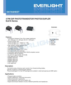
EL816 श्रृंखला उद्योग-मानक 4-पिन ड्यूल इन-लाइन पैकेज (DIP) फोटोट्रांजिस्टर ऑप्टोकपलर परिवार का प्रतिनिधित्व करती है। ये उपकरण विभिन्न क्षमताओं वाले सर्किटों के बीच विश्वसनीय विद्युत अलगाव और सिग्नल ट्रांसमिशन प्रदान करने के लिए डिज़ाइन किए गए हैं। प्रत्येक इकाई एक कॉम्पैक्ट पैकेज के भीतर एक इन्फ्रारेड एमिटिंग डायोड को एकीकृत करती है, जो एक सिलिकॉन फोटोट्रांजिस्टर डिटेक्टर के साथ ऑप्टिकली युग्मित है।
इसका मुख्य कार्य विद्युतीय पृथक्करण है, जो ग्राउंड लूप को रोकता है, उच्च वोल्टेज क्षणिकों को अवरुद्ध करता है, और विभिन्न संदर्भ ग्राउंड या वोल्टेज स्तरों वाले सर्किटों के बीच संकेत संचारित करने की अनुमति देता है। यह श्रृंखला अपने मजबूत निर्माण की विशेषता है, जो सरल स्विच डिटेक्शन से लेकर रैखिक संकेत संचरण तक विभिन्न अनुप्रयोग आवश्यकताओं को पूरा करने के लिए उच्च पृथक्करण वोल्टेज और व्यापक करंट ट्रांसफर रेशियो (CTR) ग्रेड प्रदान करती है।
2. तकनीकी मापदंडों का गहन विश्लेषण
2.1 पूर्ण अधिकतम रेटिंग
ये रेटिंग्स उन तनाव सीमाओं को परिभाषित करती हैं जो स्थायी क्षति का कारण बन सकती हैं। डिवाइस इन सीमा स्थितियों के तहत काम करने के लिए अभिप्रेत नहीं है।
- इनपुट (LED पक्ष):इन्फ्रारेड डायोड की अधिकतम निरंतर अग्र धारा (IF) 60 mA है। 1 µs अवधि के लिए 1 A के संक्षिप्त स्पंड की अनुमति है। अधिकतम रिवर्स वोल्टेज (VR) 6 V है, जो सही ध्रुवता संरक्षण की आवश्यकता पर जोर देता है।
- आउटपुट (ट्रांजिस्टर पक्ष):फोटोट्रांजिस्टर 50 mA का कलेक्टर करंट (IC) और 80 V का कलेक्टर-एमिटर वोल्टेज (VCEO) सहन कर सकता है। कम एमिटर-कलेक्टर वोल्टेज (VECO= 6V) फोटोट्रांजिस्टर जंक्शन की असममितता को दर्शाता है।
- पृथक्करण और तापीय विशेषताएँ:एक महत्वपूर्ण विनिर्देश अलगाव वोल्टेज (VISO) 5000 V हैrms(1 मिनट के लिए), परीक्षण के दौरान पिन 1-2 शॉर्ट किए गए और पिन 3-4 शॉर्ट किए गए। डिवाइस का कार्यशील तापमान सीमा -55°C से +110°C है और यह 260°C पर 10 सेकंड के सोल्डरिंग तापमान को सहन कर सकता है।
- बिजली की खपत:डिवाइस की कुल बिजली खपत (PTOT) 200 mW है। इनपुट डायोड 100°C तक 100 mW का अपव्यय बिना डेरेटिंग के कर सकता है। आउटपुट ट्रांजिस्टर की रेटेड पावर डिसिपेशन 150 mW है, जिसे 80°C से ऊपर 5.8 mW/°C की दर से डेरेट किया जाना चाहिए।
2.2 प्रकाशविद्युत विशेषताएँ
ये पैरामीटर सामान्य ऑपरेटिंग स्थितियों में डिवाइस के प्रदर्शन को परिभाषित करते हैं (जब तक कि अन्यथा निर्दिष्ट न हो, Ta= 25°C)।
2.2.1 इनपुट डायोड विशेषताएँ
- फॉरवर्ड वोल्टेज (VF):टाइपिकल मान 1.2V है, IF= 20 mA पर अधिकतम 1.4V। यह मान करंट-लिमिटिंग रेसिस्टर के मान की गणना के लिए उपयोग किया जाता है।
- रिवर्स करंट (IR):VR= 4V पर अधिकतम 10 µA, जो डायोड के अच्छे रिवर्स विशेषता को दर्शाता है।
- इनपुट कैपेसिटेंस (Cin):250 pF तक, जो उच्च-आवृत्ति ड्राइव सर्किट डिजाइन को प्रभावित कर सकता है।
2.2.2 आउटपुट ट्रांजिस्टर विशेषताएँ
- डार्क करंट (ICEO):LED बंद होने पर लीकेज करंट VCE= 20V पर अधिकतम 100 nA, जो "ऑफ स्टेट" के शोर तल को परिभाषित करता है।
- ब्रेकडाउन वोल्टेज: BVCEO≥ 80V और BVECO≥ 6V, जो वोल्टेज अवरोध क्षमता की पुष्टि करता है।
2.3 ट्रांसमिशन विशेषताएँ
ये अनुप्रयोग डिजाइन में सबसे महत्वपूर्ण पैरामीटर हैं, जो इनपुट करंट और आउटपुट करंट के बीच संबंध को परिभाषित करते हैं।
- करंट ट्रांसफर रेशियो (CTR):यह आउटपुट कलेक्टर करंट (IC) और इनपुट फॉरवर्ड करंट (IF) का अनुपात है, जिसे प्रतिशत में व्यक्त किया जाता है। EL816 श्रृंखला मानक परिस्थितियों में परीक्षण (अधिकांश मॉडलों के लिए, IF= 5mA, VCE= 5V; I/J/K ग्रेड के लिए, IF= 10mA) के तहत CTR ग्रेड की एक विस्तृत श्रृंखला प्रदान करती है। सीमाएं शामिल हैं:
- EL816: 50% से 600% (वाइड रेंज, अनग्रेडेड)
- EL816A: 80% से 160%
- EL816B: 130% से 260%
- EL816C: 200% से 400%
- EL816D: 300% से 600%
- EL816X: 100% से 200%
- EL816Y: 150% से 300%
- EL816I: 63% से 125% (IF=10mA पर)
- EL816J: 100% से 200% (IF=10mA पर)
- EL816K: 160% से 320% (IF=10mA पर)
- संतृप्ति वोल्टेज (VCE(sat)):IF=20mA, IC=1mA पर, विशिष्ट मान 0.1V (अधिकतम 0.2V) है। यह कम मान डिजिटल स्विचिंग अनुप्रयोगों में विश्वसनीय "लो" लॉजिक स्तर प्राप्त करने के लिए महत्वपूर्ण है।
- पृथक्करण प्रतिरोध और धारिता: RIO> 5×10¹⁰Ω और CIO <1.0 pF。高电阻确保漏电流最小,而低电容对于在嘈杂环境中保持高共模瞬变抗扰度(CMTI)至关重要。
- आवृत्ति प्रतिक्रिया:कट-ऑफ आवृत्ति (fc) का विशिष्ट मान 80 kHz है, जो एनालॉग सिग्नल ट्रांसमिशन के उपयोगी बैंडविड्थ को परिभाषित करता है।
- स्विचिंग गति:निर्दिष्ट परीक्षण स्थितियों के तहत (Ir=2mA, Rf=100Ω), उदय समय (tC) और पतन समय (tL) का विशिष्ट मान क्रमशः 4 µs और 3 µs (प्रत्येक का अधिकतम 18 µs) है। यह अधिकतम डिजिटल स्विचिंग आवृत्ति निर्धारित करता है।
3. ग्रेडिंग सिस्टम विवरण
EL816 श्रृंखला केवल करंट ट्रांसफर रेशियो (CTR) पर आधारित एक सटीक ग्रेडिंग प्रणाली का उपयोग करती है।
- CTR ग्रेडिंग:उपकरणों को निर्दिष्ट परीक्षण धारा पर मापे गए CTR के आधार पर विभिन्न श्रेणियों (A, B, C, D, X, Y, I, J, K) में वर्गीकृत किया जाता है। यह डिजाइनरों को गारंटीकृत लाभ सीमा वाले घटकों का चयन करने में सक्षम बनाता है, जिससे सर्किट की स्थिरता और उपज में सुधार होता है। उदाहरण के लिए, EL816C (200-400%) का चयन EL816A (80-160%) की तुलना में उच्च न्यूनतम लाभ सुनिश्चित करता है, जो कम LED ड्राइव धारा के उपयोग या अधिक आउटपुट धारा मार्जिन प्रदान करने की अनुमति दे सकता है।
- कोई तरंगदैर्ध्य/रंग श्रेणीकरण नहीं:चूंकि एमिटर एक इन्फ्रारेड डायोड है, इसलिए दृश्यमान प्रकाश तरंगदैर्ध्य या रंग श्रेणीकरण लागू नहीं होता है। फोटोट्रांजिस्टर इसके मिलान वाले LED द्वारा उत्सर्जित इन्फ्रारेड स्पेक्ट्रम के प्रति संवेदनशील है।
4. प्रदर्शन वक्र विश्लेषण
हालांकि प्रदान किया गया पाठ विशिष्ट वक्रों का विस्तृत विवरण नहीं देता, निम्नलिखित विवरण वर्णित मापदंडों के आधार पर इस प्रकार के उपकरणों के विशिष्ट प्रदर्शन प्रवृत्तियों का विश्लेषण करता है।
- CTR बनाम फॉरवर्ड करंट (IF):CTR स्थिर नहीं है; यह आमतौर पर एक विशिष्ट IFपर चरम पर होता है और बहुत कम या बहुत अधिक धारा पर गिर जाता है। 5mA और 10mA (और कुछ श्रेणियों में 1mA) पर CTR का निर्दिष्ट होना इस गैर-रैखिकता का संकेत देता है। डिजाइनरों को पूर्वानुमानित लाभ प्राप्त करने के लिए परीक्षण स्थितियों के निकट कार्य करना चाहिए।
- CTR बनाम तापमान:CTR में आमतौर पर नकारात्मक तापमान गुणांक होता है; यह तापमान बढ़ने के साथ घटता है। व्यापक कार्यशील तापमान सीमा (-55°C से +110°C) के लिए चरम पर्यावरणीय डिज़ाइन में इस डीरेटिंग पर विचार करने की आवश्यकता होती है।
- स्विचिंग समय और लोड रेसिस्टेंस (RL):निर्दिष्ट trऔर tfको RL=100Ω की स्थिति में मापा गया है। स्विचिंग गति RLऔर किसी भी परजीवी कैपेसिटेंस से काफी प्रभावित होती है। छोटा RLआमतौर पर स्विच-ऑफ समय तेज़ करता है, लेकिन बिजली की खपत बढ़ा सकता है।
- फॉरवर्ड वोल्टेज और तापमान:डायोड VFइसमें नकारात्मक तापमान गुणांक है, जो लगभग प्रति °C 2 mV की कमी दर्शाता है। CTR की तापमान निर्भरता की तुलना में, यह एक गौण प्रभाव है।
5. यांत्रिक एवं पैकेजिंग जानकारी
यह श्रृंखला विभिन्न PCB असेंबली प्रक्रियाओं और पिच आवश्यकताओं के अनुरूप विभिन्न पैकेजिंग विकल्प प्रदान करती है।
- मानक DIP प्रकार:मानक पिन पिच के साथ एक क्लासिक थ्रू-होल पैकेज।
- M विकल्प प्रकार:एक थ्रू-होल पैकेज जिसमें "वाइड पिन बेंड" है, जो क्रीपेज दूरी/विद्युत अंतराल बढ़ाने या विशिष्ट सॉकेट के साथ संगतता के लिए 0.4 इंच (लगभग 10.16 मिमी) की पिन पिच प्रदान करता है।
- S1 विकल्प प्रकार:एक "पतला" सतह माउंट (SMD) लीड प्रारूप। टेप और रील (TU या TD) के रूप में आपूर्ति, प्रति रील 1500 टुकड़े।
- S2 विकल्प प्रकार:एक और SMD पतला लीड प्रारूप, अलग पैकेज आकार के साथ, टेप और रील के रूप में आपूर्ति, प्रति रील 2000 टुकड़े।
- क्रीपेज दूरी:7.62 मिमी से अधिक, जो उच्च अलगाव वोल्टेज पर प्रबलित इन्सुलेशन के लिए सुरक्षा मानकों को पूरा करने के लिए महत्वपूर्ण है।
- डिवाइस मार्किंग:पैकेज पर "EL" (निर्माता कोड), "816" (डिवाइस पार्ट नंबर), CTR ग्रेड (R) दर्शाने वाला अक्षर और एक अंक का वर्ष कोड (Y) सप्ताह संख्या (WW) के साथ अंकित है।
6. सोल्डरिंग एवं असेंबली मार्गदर्शिका
पूर्ण अधिकतम रेटिंग्स और पैकेजिंग विकल्पों के आधार पर।
- वेल्डिंग तापमान:डिवाइस 10 सेकंड के लिए 260°C चरम वेल्डिंग तापमान का सामना कर सकता है। यह मानक लीड-फ्री (SnAgCu) रीफ्लो प्रोफ़ाइल के साथ संगत है।
- नमी संवेदनशीलता:हालांकि अंश में स्पष्ट रूप से उल्लेख नहीं किया गया है, एसएमडी घटकों (S1, S2 विकल्प) में आमतौर पर नमी संवेदनशीलता स्तर (MSL) होता है। रीफ्लो के दौरान "पॉपकॉर्न" प्रभाव को रोकने के लिए, निर्माता के हैंडलिंग निर्देशों का पालन करना महत्वपूर्ण है, जिसमें निर्धारित समय से अधिक पर्यावरणीय हवा के संपर्क में आने पर बेकिंग शामिल है।
- भंडारण स्थितियाँ:भंडारण तापमान सीमा -55°C से +125°C है। घटकों को शुष्क, नियंत्रित वातावरण में संग्रहित किया जाना चाहिए।
- अनुशंसित पैड लेआउट:डेटाशीट S1 और S2 सरफेस माउंट विकल्पों के लिए विशिष्ट पैड पैटर्न सिफारिशें प्रदान करती है। विश्वसनीय सोल्डर जोड़ और यांत्रिक स्थिरता बनाने के लिए इन सिफारिशों का उपयोग करना महत्वपूर्ण है।
7. पैकेजिंग एवं आर्डर जानकारी
पार्ट नंबर निम्नलिखित प्रारूप का पालन करता है: EL816X(Y)(Z)-FV
- X (पिन प्रकार):S1, S2, M या कोई नहीं (मानक DIP)।
- Y (CTR ग्रेड):A, B, C, D, X, Y, I, J, K या कोई नहीं (अश्रेणीकृत)।
- Z (रील)।TU, TD (SMD विकल्प के लिए) या कोई नहीं।
- F (लीड फ्रेम)।F लोहे को दर्शाता है, रिक्त स्थान तांबे को दर्शाता है।
- V।वैकल्पिक VDE सुरक्षा प्रमाणन चिह्न।
पैकिंग मात्रा।थ्रू-होल घटक ट्यूब पैकेजिंग में उपलब्ध हैं, प्रति ट्यूब 100 टुकड़े। एसएमडी घटक टेप और रील में उपलब्ध हैं: एस1 प्रति रील 1500 टुकड़े, एस2 प्रति रील 2000 टुकड़े।
8. अनुप्रयोग सुझाव
8.1 विशिष्ट अनुप्रयोग परिदृश्य
- प्रोग्रामेबल लॉजिक कंट्रोलर (PLC):डिजिटल I/O मॉड्यूल को सेंट्रल प्रोसेसिंग यूनिट और फील्ड डिवाइसेज से आइसोलेट करना।
- सिस्टम उपकरण और मापन उपकरण:पावर सप्लाई, डेटा अधिग्रहण प्रणालियों और परीक्षण उपकरणों में आइसोलेशन प्रदान करना।
- दूरसंचार उपकरण:मॉडेम, इंटरफेस और नेटवर्क उपकरणों में सिग्नल लाइनों को अलग करना।
- घरेलू उपकरण:पंखा हीटर, वॉशिंग मशीन आदि उपकरणों के नियंत्रण सर्किट में, मेन्स से जुड़े घटकों का कम वोल्टेज नियंत्रण सुरक्षित रूप से करने के लिए।
- सामान्य सिग्नल ट्रांसमिशन:कोई भी अनुप्रयोग जहाँ सर्किटों के बीच वोल्टेज स्तर परिवर्तन या ग्राउंड लूप को समाप्त करने की आवश्यकता हो।
8.2 डिज़ाइन ध्यान देने योग्य बातें
- एलईडी करंट लिमिटिंग:हमेशा I सेट करने के लिए श्रृंखला प्रतिरोध का उपयोग करेंF। R की गणना करेंlimit= (VCC- VF) / IF। पूर्वानुमेय लाभ के लिए CTR परीक्षण स्थितियों (5mA या 10mA) के आसपास कार्य करें।
- आउटपुट लोड:कलेक्टर पर लोड रेसिस्टर (RL) स्विचिंग स्पीड, आउटपुट स्विंग और पावर खपत को प्रभावित करता है। छोटा RLतेज़ टर्न-ऑफ स्पीड प्रदान करता है, लेकिन आउटपुट वोल्टेज स्विंग कम होता है और IC.
- शोर प्रतिरक्षा:डिजिटल अनुप्रयोगों के लिए, पर्याप्त CTR मार्जिन सुनिश्चित करें ताकि "ऑन स्टेट" में ICट्रांजिस्टर को पूरी तरह से संतृप्त कर सके (VCE(sat) <0.4V),并且“关断状态”的暗电流与偏置条件相比可以忽略不计。
- तापमान प्रभाव:उच्च तापमान पर CTR के क्षय पर विचार करें। एक अनुमानित नियम के रूप, 25°C से ऊपर प्रत्येक डिग्री के लिए उपलब्ध CTR को 0.5% से 1% तक डीरेट करें। सुनिश्चित करें कि डिवाइस संपूर्ण ऑपरेटिंग तापमान सीमा में पावर डिसिपेशन सीमा के भीतर रहे।
- उच्च वोल्टेज लेआउट:5000Vrmsके अलगाव रेटिंग को बनाए रखने के लिए, PCB लेआउट को सुरक्षा मानकों (जैसे IEC 60664-1) में निर्धारित क्रीपेज दूरी और विद्युत अंतराल का पालन करना चाहिए। इसका आमतौर पर मतलब है कि पैकेज के नीचे स्लॉट या अलगाव बैंड रखना।
9. तकनीकी तुलना एवं विभेदीकरण
EL816 श्रृंखला विनिर्देशों द्वारा प्रदर्शित प्रमुख लाभ:
- उच्च अलगाव वोल्टेज:5000Vrmsएक मजबूत रेटिंग है जो कई औद्योगिक और मेन्स-कनेक्टेड अनुप्रयोगों के लिए उपयुक्त है।
- व्यापक CTR चयन:व्यापक ग्रेडेशन (9 अलग-अलग ग्रेड और एक अनग्रेडेड संस्करण) लागत और प्रदर्शन के अनुकूलन के लिए उत्कृष्ट डिज़ाइन लचीलापन प्रदान करती है।
- विस्तारित तापमान सीमा:+110°C तक का कार्य तापमान, कई मानक ऑप्टोकपलर की विशिष्ट +85°C या +100°C सीमा से अधिक, इसे अधिक कठोर वातावरण में उपयोग के लिए उपयुक्त बनाता है।
- पैकेज विविधता:थ्रू-होल (मानक और वाइड-बॉडी) और दो लो-प्रोफाइल SMD विकल्प प्रदान करता है, जो आधुनिक और पारंपरिक असेंबली प्रक्रियाओं की आवश्यकताओं को पूरा करते हैं।
- अनुपालन:यह डिवाइस प्रमुख उद्योग मानकों का अनुपालन करता है: हैलोजन-मुक्त (कॉपर लीड फ्रेम संस्करण के लिए), RoHS, EU REACH, और UL, cUL, VDE, SEMKO, NEMKO, DEMKO, FIMKO, और CQC से प्रमाणित है, जो वैश्विक बाजार में प्रवेश को सुविधाजनक बनाता है।
10. सामान्य प्रश्न (तकनीकी मापदंडों पर आधारित)
- प्रश्न: EL816 और EL816A/B/C आदि में क्या अंतर है?
उत्तर: प्रत्यय CTR ग्रेड को दर्शाता है। EL816 एक अवर्गीकृत घटक है जिसमें एक विस्तृत CTR रेंज (50-600%) है। EL816A, B, C, D, X, Y, I, J, K ग्रेडेड घटक हैं जिनमें अधिक सख्त, गारंटीकृत CTR रेंज होती है, जो अधिक सटीक सर्किट डिजाइन की अनुमति देती है। - प्रश्न: क्या मैं इसका उपयोग एनालॉग सिग्नल ट्रांसमिशन के लिए कर सकता हूं?
उत्तर: हां, लेकिन सीमाओं के साथ। विशिष्ट बैंडविड्थ 80 kHz है, और CTR IFऔर तापमान के साथ गैर-रैखिक रूप से बदलता है। यह कम आवृत्ति या कम सटीकता वाले एनालॉग इन्सुलेशन के लिए उपयुक्त है। उच्च प्रदर्शन के लिए, समर्पित लीनियर ऑप्टोकपलर या इन्सुलेशन एम्पलीफायर की सिफारिश की जाती है। - प्रश्न: उपयुक्त CTR ग्रेड कैसे चुनें?
उत्तर: डिजिटल स्विचिंग के लिए, एक ऐसा ग्रेड चुनें जो आपके कार्यशील IFन्यूनतम CTR पर्याप्त I प्रदान कर सकता हैCआपके लोड को चलाने के लिए (उदाहरण के लिए, एक लॉजिक इनपुट को लो करने के लिए) और कुछ मार्जिन छोड़ने के लिए। उदाहरण के लिए, यदि आपको IC=5mA पर IF> 1mA,则需要CTR > 20%。更高的等级(例如C或D)提供更大的余量。对于简单的开关检测,较低的等级(A、I)可能更具成本效益。 - 问:“爬电距离 > 7.62 mm”对我的PCB设计意味着什么?
उत्तर: क्रीपेज दूरी इन्सुलेशन सतह के साथ दो संवाहक भागों के बीच की न्यूनतम दूरी है। निर्दिष्ट इन्सुलेशन रेटिंग बनाए रखने के लिए, आपको यह सुनिश्चित करना चाहिए कि इनपुट और आउटपुट साइड के PCB कॉपर ट्रेस/पैड घटक के नीचे बोर्ड की सतह पर भी कम से कम इस दूरी (या प्रासंगिक सुरक्षा मानकों के अनुसार अधिक) को बनाए रखें।
11. व्यावहारिक डिज़ाइन उदाहरण
परिदृश्य:एक अलग सर्किट पर 12V रिले कॉइल को नियंत्रित करने के लिए एक 3.3V माइक्रोकंट्रोलर GPIO पिन को अलग करना।
- घटक चयन:अच्छे लाभ मार्जिन के लिए EL816C (CTR 200-400%) चुनें। प्रोटोटाइपिंग के लिए मानक DIP पैकेज का उपयोग करें।
- इनपुट सर्किट:माइक्रोकंट्रोलर पिन आउटपुट 3.3V है। VF~ 1.2V। लक्ष्य IF= 5mA (मानक परीक्षण स्थितियाँ)।
Rlimit= (3.3V - 1.2V) / 0.005A = 420Ω। मानक 470Ω रेसिस्टर का उपयोग करें। वास्तविक IF≈ (3.3-1.2)/470 = 4.5mA। - आउटपुट सर्किट:रिले कॉइल ऑपरेटिंग वोल्टेज 12V, कॉइल प्रतिरोध 240Ω (50mA आवश्यक)। ऑप्टोकपलर का IC(max)50mA है, जो सीमा तक पहुँच गया है। एक बेहतर डिज़ाइन ऑप्टोकपलर का उपयोग करके एक ट्रांजिस्टर को चलाना है, जो बदले में रिले को चलाता है। प्रदर्शन के लिए, मान लें कि एक छोटे सिग्नल रिले का उपयोग किया जाता है जिसमें 12V, 100Ω कॉइल (120mA) है। ऑप्टोकपलर इसे सीधे नहीं चला सकता।
इसके बजाय, फोटोट्रांजिस्टर को एक स्विच के रूप में कॉन्फ़िगर करें जो एक NPN ट्रांजिस्टर (जैसे 2N2222) के बेस को ग्राउंड करने के लिए खींचता है। फोटोट्रांजिस्टर का कलेक्टर 12V सप्लाई से 10kΩ पुल-अप रेसिस्टर के माध्यम से जुड़ा होता है और NPN के बेस से जुड़ा होता है। एमिटर ग्राउंडेड है। जब LED चालू होता है, तो फोटोट्रांजिस्टर संतृप्त हो जाता है, NPN बेस को नीचे खींचता है और इसे बंद कर देता है। जब LED बंद होता है, तो 10kΩ रेसिस्टर NPN बेस को उच्च खींचता है, इसे चालू करता है और रिले को शक्ति प्रदान करता है। रिले कॉइल के पार एक फ्रीव्हीलिंग डायोड अवश्य लगाया जाना चाहिए। - अलगाव:12V रिले पावर सप्लाई और 3.3V माइक्रोकंट्रोलर पावर सप्लाई पूरी तरह से स्वतंत्र होनी चाहिए, कोई सामान्य ग्राउंड कनेक्शन नहीं, अलगाव बनाए रखने के लिए।
12. कार्य सिद्धांत
EL816 एक ऑप्टोइलेक्ट्रॉनिक उपकरण है। इनपुट साइड (पिन 1-एनोड और 2-कैथोड) पर लगाया गया करंट इन्फ्रारेड लाइट एमिटिंग डायोड (LED) को फोटॉन उत्सर्जित करने के लिए प्रेरित करता है। ये फोटॉन एक पारदर्शी इन्सुलेटिंग गैप (आमतौर पर मोल्डेड प्लास्टिक) से होकर गुजरते हैं और आउटपुट साइड (पिन 3-एमिटर और 4-कलेक्टर) पर सिलिकॉन NPN फोटोट्रांजिस्टर के बेस क्षेत्र पर आपतित होते हैं।
आपतित फोटॉन ट्रांजिस्टर के बेस-कलेक्टर जंक्शन में इलेक्ट्रॉन-होल युग्म उत्पन्न करते हैं, जो प्रभावी रूप से बेस करंट का कार्य करता है। फिर, इस फोटोजेनरेटेड करंट को ट्रांजिस्टर के करंट गेन (hFE) द्वारा प्रवर्धित किया जाता है, जिसके परिणामस्वरूप पिन 4 और 3 के बीच एक बड़ा कलेक्टर करंट प्रवाहित होता है। मुख्य बात यह है कि सिग्नल विद्युत कनेक्शन के बजाय प्रकाश के माध्यम से प्रसारित होता है, जिससे इनपुट और आउटपुट सर्किट के बीच विद्युत पृथक्करण प्रदान किया जाता है। आउटपुट कलेक्टर करंट और इनपुट LED करंट का अनुपात करंट ट्रांसफर रेशियो (CTR) है।
13. तकनीकी रुझान
EL816 जैसे फोटोट्रांजिस्टर ऑप्टोकपलर एक परिपक्व और लागत-प्रभावी पृथक्करण तकनीक का प्रतिनिधित्व करते हैं। पृथक्करण घटक बाजार के वर्तमान रुझानों में शामिल हैं:
- उच्च गति:100 Mbps से अधिक गति वाले संचार इंटरफेस (USB, SPI, I2C) के लिए CMOS और RF युग्मन तकनीकों पर आधारित तेज़ डिजिटल आइसोलेटरों की मांग।
- एकीकृत कार्यक्षमता:एकल पैकेज में बिजली आपूर्ति (isoPower) या गेट ड्राइवर (अलग गेट ड्राइवर) को एकीकृत करने वाले आइसोलेटरों की संख्या बढ़ रही है।
- लघुरूपण:पीसीबी स्थान बचाने के लिए, विशेष रूप से सतह माउंट विकल्पों में, छोटे पैकेज आकार और पतली मोटाई की ओर निरंतर प्रयास।
- बढ़ी हुई विश्वसनीयता और मजबूती:मोटर ड्राइव और पावर सिस्टम में आम तेज वोल्टेज स्पाइक्स को सहन करने के लिए कॉमन-मोड ट्रांजिएंट इम्युनिटी (CMTI) बढ़ाने, और ऑपरेटिंग लाइफ व तापमान रेंज बढ़ाने पर ध्यान केंद्रित।
- ऑप्टोकपलर की भूमिका:नई तकनीकों के उभरने के बावजूद, पारंपरिक ऑप्टोकपलर लागत-संवेदनशील अनुप्रयोगों, मध्यम से कम गति वाले डिजिटल आइसोलेशन, और उच्च आइसोलेशन वोल्टेज तथा सिद्ध दीर्घकालिक विश्वसनीयता महत्वपूर्ण क्षेत्रों में मजबूत स्थिति बनाए हुए हैं। उनकी सरलता और मजबूती उनकी निरंतर प्रासंगिकता सुनिश्चित करती है।
LED विनिर्देशन शब्दावली का विस्तृत विवरण
LED तकनीकी शब्दावली की पूर्ण व्याख्या
1. प्रकाशविद्युत प्रदर्शन के मुख्य मापदंड
| शब्दावली | इकाई/प्रतिनिधित्व | सामान्य व्याख्या | यह महत्वपूर्ण क्यों है |
|---|---|---|---|
| प्रकाश दक्षता (Luminous Efficacy) | lm/W (लुमेन/वाट) | प्रति वाट विद्युत ऊर्जा से उत्सर्जित प्रकाश प्रवाह, जितना अधिक होगा उतनी अधिक ऊर्जा बचत। | यह सीधे तौर पर प्रकाश उपकरण की ऊर्जा दक्षता श्रेणी और बिजली लागत निर्धारित करता है। |
| प्रकाश प्रवाह (Luminous Flux) | lm (लुमेन) | प्रकाश स्रोत द्वारा उत्सर्जित कुल प्रकाश मात्रा, जिसे आमतौर पर "चमक" कहा जाता है। | यह निर्धारित करता है कि लैंप पर्याप्त चमकदार है या नहीं। |
| दृश्य कोण (Viewing Angle) | ° (डिग्री), जैसे 120° | वह कोण जिस पर प्रकाश तीव्रता आधी रह जाती है, यह प्रकाश पुंज की चौड़ाई निर्धारित करता है। | यह प्रकाश के प्रसार और एकरूपता को प्रभावित करता है। |
| रंग तापमान (CCT) | K (केल्विन), जैसे 2700K/6500K | प्रकाश के रंग की गर्माहट या ठंडक, कम मान पीला/गर्म, उच्च मान सफेद/ठंडा। | प्रकाश व्यवस्था के वातावरण और उपयुक्त परिदृश्यों को निर्धारित करता है। |
| रंग प्रतिपादन सूचकांक (CRI / Ra) | कोई इकाई नहीं, 0–100 | प्रकाश स्रोत द्वारा वस्तुओं के वास्तविक रंगों को पुनः प्रस्तुत करने की क्षमता, Ra≥80 उत्तम माना जाता है। | रंग सत्यता को प्रभावित करता है, शॉपिंग मॉल, आर्ट गैलरी जैसे उच्च आवश्यकता वाले स्थानों में प्रयुक्त। |
| क्रोमैटिसिटी टॉलरेंस (SDCM) | मैकएडम एलिप्स स्टेप्स, जैसे "5-step" | रंग एकरूपता का मात्रात्मक सूचक, स्टेप्स जितने कम होंगे, रंग उतने ही अधिक सुसंगत होंगे। | यह सुनिश्चित करता है कि एक ही बैच के लैंपों के रंगों में कोई अंतर न हो। |
| प्रमुख तरंगदैर्ध्य (Dominant Wavelength) | nm (नैनोमीटर), उदाहरण के लिए 620nm (लाल) | रंगीन LED रंग के संगत तरंगदैर्ध्य मान। | लाल, पीले, हरे आदि एकवर्णी LED के रंगतत्व (ह्यू) को निर्धारित करता है। |
| स्पेक्ट्रमी वितरण (Spectral Distribution) | तरंगदैर्ध्य बनाम तीव्रता वक्र | LED द्वारा उत्सर्जित प्रकाश की विभिन्न तरंगदैर्ध्य पर तीव्रता वितरण प्रदर्शित करता है। | रंग प्रतिपादन और रंग गुणवत्ता को प्रभावित करता है। |
2. विद्युत मापदंड
| शब्दावली | प्रतीक | सामान्य व्याख्या | डिज़ाइन विचार |
|---|---|---|---|
| अग्र वोल्टेज (Forward Voltage) | Vf | LED को चालू करने के लिए आवश्यक न्यूनतम वोल्टेज, एक "स्टार्ट-अप थ्रेशोल्ड" के समान। | ड्राइवर पावर सप्लाई वोल्टेज ≥ Vf होना चाहिए, कई LEDs को श्रृंखला में जोड़ने पर वोल्टेज जुड़ जाता है। |
| फॉरवर्ड करंट (Forward Current) | If | वह करंट मान जो LED को सामान्य रूप से चमकने के लिए आवश्यक है। | स्थिर धारा ड्राइव का उपयोग आमतौर पर किया जाता है, धारा चमक और आयु निर्धारित करती है। |
| अधिकतम स्पंद धारा (Pulse Current) | Ifp | अल्प अवधि के लिए सहन करने योग्य शिखर धारा, डिमिंग या फ्लैश के लिए उपयोग की जाती है। | स्पंद चौड़ाई और ड्यूटी साइकल को सख्ती से नियंत्रित किया जाना चाहिए, अन्यथा अधिक गर्मी से क्षति होगी। |
| रिवर्स वोल्टेज (Reverse Voltage) | Vr | LED द्वारा सहन की जा सकने वाली अधिकतम रिवर्स वोल्टेज, जिससे अधिक होने पर यह ब्रेकडाउन हो सकता है। | सर्किट में रिवर्स कनेक्शन या वोल्टेज स्पाइक को रोकने की आवश्यकता होती है। |
| थर्मल रेजिस्टेंस (Thermal Resistance) | Rth (°C/W) | चिप से सोल्डर पॉइंट तक गर्मी के प्रवाह का प्रतिरोध, कम मान बेहतर हीट डिसिपेशन दर्शाता है। | उच्च तापीय प्रतिरोध के लिए मजबूत ऊष्मा अपव्यय डिज़ाइन आवश्यक है, अन्यथा जंक्शन तापमान बढ़ जाता है। |
| इलेक्ट्रोस्टैटिक डिस्चार्ज इम्यूनिटी (ESD Immunity) | V (HBM), जैसे 1000V | स्थैतिक बिजली के प्रति प्रतिरोधक क्षमता, उच्च मान कम क्षति की संभावना दर्शाता है। | उत्पादन में, विशेष रूप से उच्च संवेदनशीलता वाले LED के लिए, ESD सुरक्षा उपाय आवश्यक हैं। |
3. ताप प्रबंधन एवं विश्वसनीयता
| शब्दावली | प्रमुख संकेतक | सामान्य व्याख्या | प्रभाव |
|---|---|---|---|
| जंक्शन तापमान (Junction Temperature) | Tj (°C) | एलईडी चिप के अंदर का वास्तविक कार्य तापमान। | प्रत्येक 10°C कमी से, जीवनकाल दोगुना हो सकता है; अत्यधिक तापमान से प्रकाश क्षय और रंग विस्थापन होता है। |
| ल्यूमेन ह्रास (Lumen Depreciation) | L70 / L80 (घंटे) | चमक प्रारंभिक मान के 70% या 80% तक गिरने में लगने वाला समय। | एलईडी के "उपयोगी जीवन" को सीधे परिभाषित करता है। |
| ल्यूमेन रखरखाव दर (Lumen Maintenance) | % (जैसे 70%) | एक निश्चित अवधि के उपयोग के बाद शेष चमक का प्रतिशत। | दीर्घकालिक उपयोग के बाद चमक बनाए रखने की क्षमता को दर्शाता है। |
| Color Shift | Δu′v′ या MacAdam Ellipse | उपयोग के दौरान रंग में परिवर्तन की मात्रा। | प्रकाश व्यवस्था के दृश्य की रंग एकरूपता को प्रभावित करता है। |
| थर्मल एजिंग (Thermal Aging) | सामग्री प्रदर्शन में गिरावट | दीर्घकालिक उच्च तापमान के कारण एनकैप्सुलेशन सामग्री का क्षरण। | चमक में कमी, रंग परिवर्तन या ओपन-सर्किट विफलता का कारण बन सकता है। |
4. पैकेजिंग एवं सामग्री
| शब्दावली | सामान्य प्रकार | सामान्य व्याख्या | विशेषताएं और अनुप्रयोग |
|---|---|---|---|
| पैकेजिंग प्रकार | EMC, PPA, सिरेमिक | चिप की सुरक्षा करने वाली और प्रकाशिकी एवं ऊष्मा इंटरफेस प्रदान करने वाली आवरण सामग्री। | EMC उच्च ताप सहनशील, कम लागत; सिरेमिक बेहतर ताप अपव्यय, लंबी आयु। |
| चिप संरचना | फॉरवर्ड माउंटेड, फ्लिप चिप (Flip Chip) | चिप इलेक्ट्रोड व्यवस्था विधि। | फ्लिप चिप में बेहतर हीट डिसिपेशन और उच्च प्रकाश दक्षता होती है, जो उच्च शक्ति के लिए उपयुक्त है। |
| फॉस्फर कोटिंग | YAG, सिलिकेट, नाइट्राइड | नीले प्रकाश चिप पर लगाया जाता है, जो आंशिक रूप से पीले/लाल प्रकाश में परिवर्तित होता है और सफेद प्रकाश बनाने के लिए मिश्रित होता है। | विभिन्न फॉस्फर प्रकाश दक्षता, रंग तापमान और रंग प्रतिपादन को प्रभावित करते हैं। |
| लेंस/ऑप्टिकल डिज़ाइन | समतल, माइक्रोलेंस, कुल आंतरिक परावर्तन | पैकेजिंग सतह की प्रकाशिक संरचना, प्रकाश वितरण को नियंत्रित करती है। | उत्सर्जन कोण और प्रकाश वितरण वक्र निर्धारित करता है। |
पाँच, गुणवत्ता नियंत्रण और ग्रेडिंग
| शब्दावली | ग्रेडिंग सामग्री | सामान्य व्याख्या | उद्देश्य |
|---|---|---|---|
| ल्यूमिनस फ्लक्स ग्रेडिंग | कोड जैसे 2G, 2H | चमक के स्तर के अनुसार समूहों में विभाजित, प्रत्येक समूह का न्यूनतम/अधिकतम लुमेन मान होता है। | यह सुनिश्चित करना कि एक ही बैच के उत्पादों की चमक एक समान हो। |
| वोल्टेज ग्रेडिंग | कोड जैसे 6W, 6X | फॉरवर्ड वोल्टेज रेंज के अनुसार समूहीकृत करें। | ड्राइविंग पावर स्रोत के मिलान और सिस्टम दक्षता में सुधार की सुविधा। |
| रंग ग्रेडिंग | 5-step MacAdam ellipse | रंग निर्देशांक के अनुसार समूहीकरण करें, यह सुनिश्चित करते हुए कि रंग अत्यंत सीमित सीमा के भीतर आते हैं। | रंग एकरूपता सुनिश्चित करें, एक ही प्रकाश स्रोत के भीतर रंग में असमानता से बचें। |
| रंग तापमान श्रेणीकरण | 2700K, 3000K, आदि। | रंग तापमान के अनुसार समूहीकरण करें, प्रत्येक समूह की अपनी संबंधित निर्देशांक सीमा होती है। | विभिन्न परिदृश्यों की रंग तापमान आवश्यकताओं को पूरा करना। |
छह, परीक्षण और प्रमाणन
| शब्दावली | मानक/परीक्षण | सामान्य व्याख्या | महत्व |
|---|---|---|---|
| LM-80 | लुमेन रखरखाव परीक्षण | निरंतर तापमान की स्थिति में लंबे समय तक जलाकर, चमक क्षय डेटा रिकॉर्ड करना। | एलईडी जीवनकाल का अनुमान लगाने के लिए (TM-21 के साथ संयुक्त)। |
| TM-21 | जीवनकाल प्रक्षेपण मानक | LM-80 डेटा के आधार पर वास्तविक उपयोग की स्थितियों में जीवनकाल का अनुमान लगाना। | वैज्ञानिक जीवनकाल पूर्वानुमान प्रदान करना। |
| IESNA मानक | Illuminating Engineering Society Standard | Optical, electrical, and thermal test methods are covered. | Industry-recognized testing basis. |
| RoHS / REACH | Environmental Certification | Ensures the product does not contain harmful substances (such as lead, mercury). | अंतर्राष्ट्रीय बाजार में प्रवेश की पात्रता शर्तें। |
| ENERGY STAR / DLC | ऊर्जा दक्षता प्रमाणन | प्रकाश उत्पादों के लिए ऊर्जा दक्षता और प्रदर्शन प्रमाणन। | सामान्यतः सरकारी खरीद, सब्सिडी कार्यक्रमों में उपयोग किया जाता है, बाजार प्रतिस्पर्धा बढ़ाने के लिए। |