विषयसूची
- 1. उत्पाद अवलोकन
- 2. तकनीकी मापदंडों का गहन विश्लेषण
- 2.1 प्रकाशविद्युत विशेषताएँ
- 2.2 विद्युत और ऊष्मीय मापदंड
- 3. ग्रेडिंग प्रणाली विवरण
- 4. प्रदर्शन वक्र विश्लेषण
- 5. यांत्रिक और पैकेजिंग जानकारी
- 5.1 पैकेज आयाम और लेआउट
- 5.2 ध्रुवीयता पहचान
- 6. वेल्डिंग और असेंबली गाइड
- 7. पैकेजिंग और ऑर्डर जानकारी
- 8. अनुप्रयोग सुझाव
- 8.1 विशिष्ट अनुप्रयोग परिदृश्य
- 8.2 डिज़ाइन विचार एवं सावधानियाँ
- स्पेसिफिकेशन शीट विभिन्न पर्यावरणीय और परिचालन तनावों के तहत उत्पाद की मजबूती सुनिश्चित करने के लिए व्यापक विश्वसनीयता परीक्षणों का एक सेट रेखांकित करती है। ये परीक्षण 90% आत्मविश्वास स्तर और 10% लॉट टॉलरेंस परसेंट डिफेक्टिव (LTPD) पर किए जाते हैं। प्रमुख परीक्षण परियोजनाओं में शामिल हैं:
- 67-23 श्रृंखला कई प्रमुख विशेषताओं के माध्यम से बाजार में अपनी पहचान बनाती है। मानक टॉप-व्यू LED की तुलना में, इसका एकीकृत आंतरिक परावर्तक और पैकेज ऑप्टिकल डिज़ाइन विशेष रूप से लाइट गाइड पाइप युग्मन दक्षता के लिए अनुकूलित है, जिससे प्रकाश हानि कम होती है। अत्यंत कम धारा (2mA तक कम) पर प्रभावी ढंग से कार्य करने की क्षमता अल्ट्रा-लो पावर डिज़ाइन का एक महत्वपूर्ण लाभ है, एक विशेषता जिसे प्रतिस्पर्धी उत्पादों में हमेशा प्रमुखता से नहीं दिखाया जाता है। इसके अतिरिक्त, एकल कॉम्पैक्ट P-LCC-4 पैकेज में तीन अलग-अलग प्राथमिक रंग प्रदान करना, फुल-कलर इंडिकेटर अनुप्रयोगों के लिए डिज़ाइन लचीलापन प्रदान करता है, बिना अलग-अलग मोनोक्रोम LED के लिए अतिरिक्त PCB स्थान की आवश्यकता के।
- प्रश्न: यदि मेरी बिजली आपूर्ति LED के विशिष्ट फॉरवर्ड वोल्टेज पर सटीक रूप से नियंत्रित है, तो क्या मैं इन LED को करंट-लिमिटिंग रेसिस्टर के बिना चला सकता हूँ?
- परिदृश्य: मेडिकल उपकरण के लिए बैकलिट फिल्म स्विच पैनल डिजाइन करना।
- लाइट एमिटिंग डायोड (LED) एक सेमीकंडक्टर डिवाइस है जो इलेक्ट्रोल्यूमिनेसेंस के माध्यम से प्रकाश उत्सर्जित करती है। जब p-n जंक्शन पर फॉरवर्ड वोल्टेज लगाया जाता है, तो n-टाइप सामग्री से इलेक्ट्रॉन और p-टाइप सामग्री से होल सक्रिय क्षेत्र में पुनर्संयोजित होते हैं। यह पुनर्संयोजन प्रक्रिया फोटॉन (प्रकाश) के रूप में ऊर्जा मुक्त करती है। उत्सर्जित प्रकाश की विशिष्ट तरंगदैर्ध्य (रंग) सक्रिय क्षेत्र में प्रयुक्त सेमीकंडक्टर सामग्री के ऊर्जा बैंड गैप द्वारा निर्धारित होती है। 67-23 श्रृंखला विभिन्न सामग्री प्रणालियों का उपयोग करती है: लाल और पीले-हरे चिप्स के लिए AlGaInP, और नीले चिप्स के लिए InGaN/SiC। पैकेजिंग लेंस और आंतरिक परावर्तक उत्सर्जित प्रकाश को आकार देने और निर्देशित करने के लिए उपयोग किए जाते हैं, जिससे वांछित व्यूइंग एंगल पैटर्न बनता है।
- 67-23 श्रृंखला जैसे LEDs का विकास ऑप्टोइलेक्ट्रॉनिक्स क्षेत्र में व्यापक प्रवृत्ति का एक हिस्सा है। उद्योग उच्च दक्षता (प्रति वाट अधिक लुमेन) की ओर निरंतर धक्का दे रहा है, जो समान शक्ति पर चमकदार आउटपुट या कम शक्ति पर समान आउटपुट की अनुमति देता है - दोनों ही पोर्टेबल और ऊर्जा-सचेत अनुप्रयोगों के लिए फायदेमंद हैं। पैकेजिंग लघुरूपण एक और प्रमुख प्रवृत्ति है, जो LEDs को तेजी से छोटे उपकरणों में एकीकृत करने में सक्षम बनाती है। इसके अलावा, उन्नत डिस्प्ले और सिग्नल अनुप्रयोगों की मांगों को पूरा करने के लिए सटीक और सुसंगत रंग विशेषताओं वाले LEDs की बाजार मांग बढ़ रही है। व्यापक व्यूइंग एंगल और लाइट गाइड प्लेट्स के साथ संगतता पर जोर, ऑटोमोटिव, औद्योगिक और उपभोक्ता उत्पादों में जटिल ह्यूमन-मशीन इंटरफेस (HMI) की बढ़ती महत्वपूर्णता को दर्शाता है, जहां समान और सौंदर्यपूर्ण प्रकाश व्यवस्था एक महत्वपूर्ण डिजाइन तत्व है।
- LED विनिर्देश शब्दावली का विस्तृत विवरण
- 1. प्रकाशविद्युत प्रदर्शन के मुख्य मापदंड
- 2. विद्युत मापदंड
- 3. ताप प्रबंधन एवं विश्वसनीयता
- 4. पैकेजिंग एवं सामग्री
- पाँच, गुणवत्ता नियंत्रण और ग्रेडिंग
- छह, परीक्षण और प्रमाणन
1. उत्पाद अवलोकन
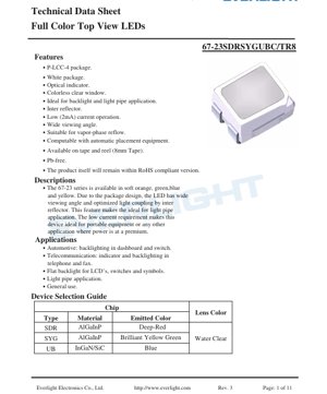
67-23 श्रृंखला सतह माउंट अनुप्रयोगों के लिए डिज़ाइन किए गए फुल-कलर टॉप-व्यू लाइट एमिटिंग डायोड (LED) का एक वर्ग है। यह श्रृंखला कॉम्पैक्ट P-LCC-4 (प्लास्टिक लीडेड चिप कैरियर, 4-पिन) एनकैप्सुलेशन का उपयोग करती है और एक पारदर्शी रंगहीन विंडो से सुसज्जित है, जो एक विस्तृत और समान प्रकाश उत्सर्जन पैटर्न प्रदान करती है। इसका मूल डिज़ाइन दर्शन बैकलाइट और लाइट गाइड ट्यूब (लाइट पाइप) सिस्टम के लिए इष्टतम प्रदर्शन प्राप्त करना है, जिससे यह स्थान और ऊर्जा दक्षता की कठोर आवश्यकताओं वाले अनुप्रयोगों के लिए एक आदर्श विकल्प बन जाता है।
इस श्रृंखला का मुख्य लाभ इसका अत्यंत चौड़ा दृश्य कोण है, जो पैकेजिंग डिज़ाइन और एकीकृत आंतरिक परावर्तक के कारण संभव हुआ है। यह विशेषता विस्तृत क्षेत्र में चमक की एकरूपता सुनिश्चित करती है, जो संकेतक लैंप और बैकलाइट अनुप्रयोगों के लिए महत्वपूर्ण है। इसके अतिरिक्त, यह उपकरण कम धारा पर कार्य करने के लिए डिज़ाइन किया गया है, जिसका विशिष्ट अग्र धारा 20mA है और यह 2mA तक कम पर भी संचालित हो सकता है। यह कम बिजली खपत विशेषता इसे विशेष रूप से बैटरी से चलने वाले पोर्टेबल इलेक्ट्रॉनिक्स और अन्य उपकरणों के लिए उपयुक्त बनाती है जहां ऊर्जा खपत कम करना प्राथमिकता है। यह श्रृंखला कई प्रकाश उत्सर्जक रंग प्रदान करती है, जिसमें गहरा लाल, चमकीला पीला-हरा और नीला शामिल हैं, जिससे विविध डिज़ाइन अनुप्रयोग संभव होते हैं।
2. तकनीकी मापदंडों का गहन विश्लेषण
2.1 प्रकाशविद्युत विशेषताएँ
प्रत्येक LED रंग मॉडल का प्रदर्शन 25°C परिवेश तापमान और 20mA अग्र धारा (IF) की मानक स्थितियों में मापे गए विशिष्ट प्रकाशविद्युत मापदंडों द्वारा परिभाषित किया जाता है।
- दीप्त तीव्रता (IV):यह पैरामीटर LED की अनुभूत चमक को दर्शाता है। गहरा लाल (SDR) मॉडल सबसे अधिक विशिष्ट तीव्रता प्रदान करता है, जो 112 mcd (मिलीकैंडेला) है। चमकीला पीला-हरा (SYG) और नीला (UB) मॉडल की विशिष्ट तीव्रताएँ क्रमशः 20 mcd और 18 mcd हैं। डिज़ाइनरों को विशिष्ट चमक लक्ष्य प्राप्त करने के लिए आवश्यक LED की संख्या निर्धारित करते समय इन मूल्यों पर विचार करना चाहिए।
- तरंगदैर्ध्य विशेषताएँ:उत्सर्जित प्रकाश के रंग की सटीक परिभाषा होती है। गहरे लाल एलईडी की विशिष्ट शिखर तरंगदैर्ध्य (λp) 650 nm होती है, और प्रमुख तरंगदैर्ध्य (λd) 639 nm होती है। पीले-हरे एलईडी की उत्सर्जन तरंगदैर्ध्य 575 nm (शिखर) और 573 nm (प्रमुख तरंगदैर्ध्य) होती है। नीले एलईडी की कार्यशील तरंगदैर्ध्य 468 nm (शिखर) और 470 nm (प्रमुख तरंगदैर्ध्य) होती है। वर्णिका शुद्धता को प्रभावित करने वाली वर्णक्रमीय बैंडविड्थ (Δλ), लाल और पीले-हरे एलईडी के लिए लगभग 20 nm और नीले एलईडी के लिए लगभग 26 nm होती है।
- दृश्य कोण (2θ1/2):इस श्रृंखला की एक प्रमुख विशेषता इसका 120 डिग्री का दृश्य कोण है। यह विस्तृत दृश्य कोण सुनिश्चित करता है कि एलईडी को व्यापक कोणीय सीमा से देखा जा सके, जो पैनल संकेतक और बैकलाइट अनुप्रयोगों के लिए महत्वपूर्ण है जहाँ उपयोगकर्ता का देखने का स्थान परिवर्तित हो सकता है।
2.2 विद्युत और ऊष्मीय मापदंड
विश्वसनीय सर्किट डिजाइन के लिए विद्युत सीमाओं और ऊष्मीय व्यवहार को समझना आवश्यक है।
- Forward Voltage (VF):The voltage drop across an LED when operating. The typical VFfor red and yellow-green LEDs is 2.0V (max 2.4V), while blue LEDs require a higher typical VF, which is 3.5V (max 4.0V). This difference must be accounted for in the driving circuit, especially in multi-color designs.
- Absolute Maximum Ratings:These are the stress limits that must not be exceeded under any conditions to prevent permanent damage. Key limits include a reverse voltage (VR) of 5V for all colors. The maximum continuous forward current (IF) is 25mA for red/yellow-green and 30mA for blue. For pulsed operation (1/10 duty cycle at 1kHz frequency), the peak forward current (IFP) is higher, at 60mA for red/yellow-green and 100mA for blue. The maximum power dissipation (Pdलाल के लिए 60mW और नीले के लिए 130mW है, जो सीधे ताप प्रबंधन से संबंधित है।
- कार्यशील एवं भंडारण तापमान:डिवाइस का कार्यशील तापमान सीमा (Topr) -40°C से +85°C के लिए रेटेड है, और भंडारण तापमान सीमा (Tstg) -40°C से +100°C है, जो प्रतिकूल परिस्थितियों में भी सामान्य संचालन सुनिश्चित करता है।
- इलेक्ट्रोस्टैटिक डिस्चार्ज (ESD):लाल और पीले-हरे एलईडी के लिए मानव शरीर मॉडल (एचबीएम) ईएसडी सहनशीलता वोल्टेज 2000V है, और नीले एलईडी के लिए 1000V है। असेंबली प्रक्रिया के दौरान उचित ईएसडी हैंडलिंग प्रक्रियाओं का पालन करने की सिफारिश की जाती है।
3. ग्रेडिंग प्रणाली विवरण
उत्पाद एक बिनिंग सिस्टम का उपयोग करता है, जो महत्वपूर्ण प्रदर्शन मापदंडों के आधार पर एलईडी को वर्गीकृत करता है, जिससे उत्पादन बैच के भीतर एकरूपता सुनिश्चित होती है। रील पर लेबल तीन प्रमुख बिन दर्शाता है:
- CAT (ल्यूमिनस इंटेंसिटी ग्रेड):यह कोड मापी गई ल्यूमिनस इंटेंसिटी के आधार पर एलईडी को समूहित करता है। डिजाइनर विशिष्ट CAT बिन का चयन कर सकते हैं ताकि उनके अनुप्रयोग के लिए आवश्यक न्यूनतम चमक स्तर की गारंटी दी जा सके, जो कई एलईडी सरणियों में दृश्य एकरूपता प्राप्त करने के लिए महत्वपूर्ण है।
- HUE (डोमिनेंट वेवलेंथ ग्रेड):यह बिनिंग एलईडी की प्रमुख तरंग दैर्ध्य के आधार पर की जाती है, जो सटीक रंग बिंदु को परिभाषित करती है। ऐसे अनुप्रयोगों के लिए जिन्हें सटीक रंग मिलान की आवश्यकता होती है, जैसे स्टेटस इंडिकेटर या बहुरंगी डिस्प्ले जहां रंग एकरूपता महत्वपूर्ण है, सख्त HUE बिन का चयन करना आवश्यक है।
- REF (फॉरवर्ड वोल्टेज ग्रेड):यह कोड LED के फॉरवर्ड वोल्टेज ड्रॉप के आधार पर क्रमबद्ध है। समान REF ग्रेड के LED का उपयोग करने से करंट-लिमिटिंग रेसिस्टर डिज़ाइन सरल हो जाता है और कई LED को समानांतर में जोड़ने पर करंट वितरण समान रखने में मदद मिलती है, जिससे जीवनकाल बढ़ता है और चमक एकसमान बनी रहती है।
4. प्रदर्शन वक्र विश्लेषण
हालांकि डेटाशीट में विशिष्ट ग्राफिकल डेटा का उल्लेख किया गया है, लेकिन विशिष्ट ऑप्टोइलेक्ट्रॉनिक विशेषता वक्र आमतौर पर प्रमुख पैरामीटरों के बीच संबंध दर्शाते हैं। इन वक्रों में आमतौर पर शामिल हैं:
- Relative Luminous Intensity vs. Forward Current (I-V Curve):यह वक्र दर्शाता है कि ड्राइविंग करंट बढ़ने पर प्रकाश उत्पादन कैसे बढ़ता है। यह आमतौर पर गैर-रैखिक होता है, और अधिकतम करंट के पास संचालन से चमक में वृद्धि की दर कम हो सकती है, साथ ही डिवाइस में ऊष्मा और प्रतिबल भी बढ़ सकता है।
- Forward Voltage vs. Forward Current:यह ग्राफ डायोड के चालू होने की विशेषता को दर्शाता है। थ्रेशोल्ड वोल्टेज पार करने के बाद, वोल्टेज करंट के साथ लघुगणकीय रूप से बढ़ता है।
- प्रकाश तीव्रता और परिवेश तापमान संबंध:LED का प्रकाश उत्पादन आमतौर पर जंक्शन तापमान बढ़ने के साथ कम हो जाता है। उच्च तापमान वाले वातावरण में संचालित होने वाले अनुप्रयोगों के लिए, वांछित चमक बनाए रखने को सुनिश्चित करने हेतु इस डीरेटिंग को समझना महत्वपूर्ण है।
- स्पेक्ट्रम वितरण:सापेक्ष तीव्रता बनाम तरंगदैर्ध्य का ग्राफ, प्रत्येक रंग मॉडल के उत्सर्जन स्पेक्ट्रम के आकार और चौड़ाई को दर्शाता है।
5. यांत्रिक और पैकेजिंग जानकारी
5.1 पैकेज आयाम और लेआउट
LED, P-LCC-4 पैकेज में है, जिसका समग्र आयाम लगभग 3.2mm लंबा, 2.8mm चौड़ा और 1.9mm ऊंचा (गुंबद लेंस को छोड़कर) है। पैकेज में चार पिन हैं। शीर्ष दृश्य एकल पैकेज के भीतर तीन रंग चिप्स (लाल, हरा, नीला) के संबंधित एनोड और कैथोड कनेक्शनों को स्पष्ट रूप से दर्शाता है, जो सही PCB पैड डिजाइन और असेंबली ओरिएंटेशन के लिए महत्वपूर्ण है। रिफ्लो सोल्डरिंग प्रक्रिया के दौरान विश्वसनीय सोल्डर जोड़ बनाने को सुनिश्चित करने के लिए अनुशंसित पैड पैटर्न (पैड डिजाइन) प्रदान किए गए हैं।
5.2 ध्रुवीयता पहचान
डेटाशीट में प्रत्येक चिप की ध्रुवीयता को दर्शाने वाला आरेख शामिल है। कार्य के दौरान रिवर्स बायस को रोकने के लिए लाल, हरे और नीले डायोड के एनोड और कैथोड की सही पहचान महत्वपूर्ण है, जिससे LED क्षतिग्रस्त हो सकती है।
6. वेल्डिंग और असेंबली गाइड
ये SMD LED मानक स्वचालित प्लेसमेंट उपकरणों और सोल्डरिंग प्रक्रियाओं के साथ संगत हैं।
- रीफ्लो सोल्डरिंग:डिवाइस वेपर फेज और इन्फ्रारेड रीफ्लो सोल्डरिंग के लिए उपयुक्त है। अनुशंसित अधिकतम सोल्डरिंग तापमान प्रोफ़ाइल का पीक तापमान 260°C है, जिसकी अवधि 10 सेकंड से अधिक नहीं होनी चाहिए। प्लास्टिक एनकैप्सुलेशन और आंतरिक वायर बॉन्डिंग को थर्मल क्षति से बचाने के लिए इस तापमान प्रोफ़ाइल का कड़ाई से पालन करना चाहिए।
- हैंड सोल्डरिंग:यदि मैन्युअल सोल्डरिंग की आवश्यकता हो, तो सोल्डरिंग आयरन टिप का तापमान 350°C से अधिक नहीं होना चाहिए, और प्रत्येक पिन के साथ संपर्क का समय 3 सेकंड या उससे कम सीमित होना चाहिए। सोल्डर जॉइंट और पैकेज बॉडी के बीच पिन पर हीट सिंक का उपयोग किया जा सकता है।
- भंडारण और हैंडलिंग:एलईडी को नमी-सुरक्षात्मक पैकेजिंग में शिप किया जाता है। घटक का उपयोग करने से पहले पैकेट नहीं खोलना चाहिए। खोलने से पहले, भंडारण की स्थिति 30°C/90% RH या उससे कम होनी चाहिए। खोलने के बाद, घटक की निर्दिष्ट फ्लोर लाइफ (कारखाने के पर्यावरणीय परिस्थितियों के संपर्क में आने का समय) 168 घंटे (7 दिन) है। यदि इस समय सीमा से अधिक हो जाता है, तो सोल्डरिंग प्रक्रिया के दौरान "पॉपकॉर्न" प्रभाव या डिलैमिनेशन को रोकने के लिए रिफ्लो सोल्डरिंग से पहले बेकिंग प्रक्रिया की आवश्यकता हो सकती है।
7. पैकेजिंग और ऑर्डर जानकारी
एलईडी स्वचालित असेंबली की सुविधा के लिए रील टेप पर आपूर्ति की जाती है। कैरियर टेप की चौड़ाई 8 मिमी है। प्रत्येक मानक रील में 2000 टुकड़े होते हैं। रील टेप लेबल में महत्वपूर्ण जानकारी शामिल होती है, जिसमें घटक पार्ट नंबर (CPN), मात्रा (QTY), बैच नंबर (LOT NO) और उस रील पर एलईडी के विशिष्ट बिनिंग कोड (CAT, HUE, REF) शामिल हैं। नमी-सुरक्षात्मक पैकेजिंग में रील टेप को एल्यूमीनियम पन्नी वाले नमी-सुरक्षात्मक बैग में रखना, और साथ में डिसिकेंट और आर्द्रता संकेतक कार्ड शामिल होते हैं, ताकि भंडारण और परिवहन के दौरान घटक की सुरक्षा हो सके।
8. अनुप्रयोग सुझाव
8.1 विशिष्ट अनुप्रयोग परिदृश्य
- ऑटोमोटिव इंटीरियर:इंस्ट्रूमेंट क्लस्टर, कंट्रोल स्विच और इन्फोटेनमेंट सिस्टम बटनों की बैकलाइटिंग।
- संचार उपकरण:डेस्कटॉप फोन, मोबाइल उपकरण और फैक्स मशीनों में स्थिति संकेतक और कीपैड बैकलाइट।
- उपभोक्ता इलेक्ट्रॉनिक्स:घरेलू उपकरणों में एलसीडी डिस्प्ले की बैकलाइट, कंट्रोल पैनल पर प्रतीकों का समतल प्रकाशन और सामान्य संकेतक।
- लाइट गाइड पाइप/लाइट गाइड सिस्टम:चौड़े देखने के कोण और आंतरिक परावर्तक डिज़ाइन इन एलईडी को एक्रिलिक या पॉलीकार्बोनेट लाइट गाइड प्लेट्स में प्रकाश युग्मन करते समय विशेष रूप से प्रभावी बनाते हैं, जो किनारों से लेबल, बटन या ग्राफिक ओवरले को प्रकाशित करने में सक्षम हैं।
8.2 डिज़ाइन विचार एवं सावधानियाँ
- करंट लिमिटेशन:अवश्यप्रत्येक एलईडी या एलईडी स्ट्रिंग के साथ श्रृंखला में एक बाह्य करंट-सीमित रोकनेवाला का उपयोग करें। एलईडी का फॉरवर्ड वोल्टेज में नकारात्मक तापमान गुणांक और निर्माण सहनशीलता होती है। श्रृंखला रोकनेवाला के बिना, बिजली आपूर्ति वोल्टेज में मामूली वृद्धि से फॉरवर्ड करंट में बड़ी, यहां तक कि विनाशकारी वृद्धि हो सकती है। रोकनेवाला मान की गणना ओम के नियम का उपयोग करके की जा सकती है: R = (Vबिजली आपूर्ति- V) / IFथर्मल प्रबंधन:F.
- हालांकि बिजली की खपत कम है, पर्याप्त PCB कॉपर फ़ॉइल क्षेत्र सुनिश्चित करना (थर्मल पैड के आसपास, यदि लागू हो, या पिन के आसपास) गर्मी को दूर करने में मदद करता है, खासकर उच्च परिवेश के तापमान पर या अधिकतम धारा के करीब चलाते समय। यह प्रकाश उत्पादन और दीर्घकालिक विश्वसनीयता बनाए रखने में सहायक है।ESD संरक्षण:
- हैंडलिंग और असेंबली प्रक्रिया के दौरान मानक ESD रोकथाम उपायों को लागू करें। यदि एप्लिकेशन एक स्थिर बिजली निर्वहन उत्पन्न करने वाले वातावरण में है, तो संवेदनशील लाइनों पर ट्रांजिएंट वोल्टेज सप्रेशन (TVS) डायोड या अन्य सुरक्षा सर्किट जोड़ने पर विचार करें।9. विश्वसनीयता और गुणवत्ता आश्वासन
स्पेसिफिकेशन शीट विभिन्न पर्यावरणीय और परिचालन तनावों के तहत उत्पाद की मजबूती सुनिश्चित करने के लिए व्यापक विश्वसनीयता परीक्षणों का एक सेट रेखांकित करती है। ये परीक्षण 90% आत्मविश्वास स्तर और 10% लॉट टॉलरेंस परसेंट डिफेक्टिव (LTPD) पर किए जाते हैं। प्रमुख परीक्षण परियोजनाओं में शामिल हैं:
रीफ्लो सोल्डरिंग सहनशीलता (260°C)
- तापमान चक्रण (-40°C से +100°C)
- तापीय आघात (-10°C से +100°C)
- उच्च तापमान भंडारण (100°C)
- निम्न तापमान भंडारण (-40°C)
- DC परिचालन जीवनकाल (20mA पर 1000 घंटे)
- उच्च तापमान/उच्च आर्द्रता भंडारण (85°C/85% RH)
- इन कठोर परीक्षणों के माध्यम से यह सत्यापित किया गया है कि LED कठोर अनुप्रयोगों, जिसमें ऑटोमोटिव और औद्योगिक उपयोग शामिल हैं, के लिए उपयुक्त है।
10. तकनीकी तुलना एवं विभेदीकरण
67-23 श्रृंखला कई प्रमुख विशेषताओं के माध्यम से बाजार में अपनी पहचान बनाती है। मानक टॉप-व्यू LED की तुलना में, इसका एकीकृत आंतरिक परावर्तक और पैकेज ऑप्टिकल डिज़ाइन विशेष रूप से लाइट गाइड पाइप युग्मन दक्षता के लिए अनुकूलित है, जिससे प्रकाश हानि कम होती है। अत्यंत कम धारा (2mA तक कम) पर प्रभावी ढंग से कार्य करने की क्षमता अल्ट्रा-लो पावर डिज़ाइन का एक महत्वपूर्ण लाभ है, एक विशेषता जिसे प्रतिस्पर्धी उत्पादों में हमेशा प्रमुखता से नहीं दिखाया जाता है। इसके अतिरिक्त, एकल कॉम्पैक्ट P-LCC-4 पैकेज में तीन अलग-अलग प्राथमिक रंग प्रदान करना, फुल-कलर इंडिकेटर अनुप्रयोगों के लिए डिज़ाइन लचीलापन प्रदान करता है, बिना अलग-अलग मोनोक्रोम LED के लिए अतिरिक्त PCB स्थान की आवश्यकता के।
11. सामान्य प्रश्न (FAQ)
प्रश्न: यदि मेरी बिजली आपूर्ति LED के विशिष्ट फॉरवर्ड वोल्टेज पर सटीक रूप से नियंत्रित है, तो क्या मैं इन LED को करंट-लिमिटिंग रेसिस्टर के बिना चला सकता हूँ?
उत्तर:
ऐसा करने की दृढ़ता से अनुशंसा नहीं की जाती है, इससे LED के विफल होने की संभावना अधिक है। फॉरवर्ड वोल्टेज तापमान और अलग-अलग डिवाइस के साथ बदलता रहता है। बिजली आपूर्ति वोल्टेज में मामूली सी धनात्मक विचलन भी अत्यधिक धारा का कारण बन सकता है। हमेशा एक श्रृंखला रोकनेवाला या समर्पित नियत-धारा LED ड्राइवर का उपयोग करें।No.प्रश्न: बिनिंग कोड (CAT, HUE, REF) का उद्देश्य क्या है?
उत्तर: बिनिंग विद्युत और प्रकाशीय विशेषताओं में स्थिरता सुनिश्चित करती है। उदाहरण के लिए, यदि सरणी में दृश्य रंग एकरूपता महत्वपूर्ण है, तो सख्त HUE बिन निर्दिष्ट करने की आवश्यकता होती है। यदि चमक एकरूपता महत्वपूर्ण है, तो CAT बिन निर्दिष्ट करें। बिन किए गए घटकों का उपयोग अंतिम उत्पाद में एलईडी के बीच ध्यान देने योग्य अंतर को रोकता है।
प्रश्न: 168 घंटे के "फ्लोर लाइफ" को कैसे समझें?
उत्तर: नमी बैरियर बैग खोलने के बाद, घटक हवा से नमी अवशोषित करते हैं। यदि अत्यधिक नमी अवशोषित करने (168 घंटे की फ्लोर लाइफ से अधिक) के बाद उन्हें रिफ्लो सोल्डर किया जाता है, तो तेजी से गर्म होने से आंतरिक वाष्प दबाव हो सकता है, जिससे पैकेज दरार ("पॉपकॉर्न" प्रभाव) हो सकती है। यदि फ्लोर लाइफ से अधिक हो जाता है, तो सोल्डरिंग से पहले नमी को हटाने के लिए उपयुक्त IPC/JEDEC मानक (उदाहरण के लिए, 125°C पर 24 घंटे बेकिंग) के अनुसार घटकों को बेक करना होगा।
12. डिज़ाइन केस स्टडी उदाहरण
परिदृश्य: मेडिकल उपकरण के लिए बैकलिट फिल्म स्विच पैनल डिजाइन करना।
आवश्यकताएँ:
कई बटनों के लिए समान सफ़ेद बैकलाइट, बैटरी जीवन को बढ़ाने के लिए अति-कम बिजली खपत, और विश्वसनीय संचालन प्रदान करना।कार्यान्वयन योजना:
ग्राफिक ओवरले के पीछे पारदर्शी एक्रिलिक से बनी एक लाइट गाइड प्लेट (LGP) डिज़ाइन करें। LGP के किनारे पर कई 67-23 श्रृंखला के नीले (UB) और पीले-हरे (SYG) एलईडी रखें। एलईडी का 120 डिग्री का चौड़ा व्यूइंग एंगल सुनिश्चित करता है कि प्रकाश ऊर्जा एक्रिलिक शीट के किनारे में कुशलतापूर्वक युग्मित हो। फिर, LGP पर मुद्रित सूक्ष्म संरचनाओं के माध्यम से, प्रकाश बटन क्षेत्र में समान रूप से बिखर जाता है। नीली और पीली-हरी रोशनी (अलग-अलग PWM नियंत्रण सर्किट द्वारा संचालित) को सही अनुपात में मिलाकर, एक तटस्थ सफेद बैकलाइट प्राप्त की जा सकती है। 2mA जितनी कम न्यूनतम कार्यकारी धारा बैकलाइट को रात में उपयोग के लिए बहुत कम चमक तक मंद करने की अनुमति देती है, जिससे बैटरी जीवन में उल्लेखनीय वृद्धि होती है। P-LCC-4 पैकेजिंग डिवाइस के किनारे पर कॉम्पैक्ट PCB लेआउट की अनुमति देती है।13. कार्य सिद्धांत
लाइट एमिटिंग डायोड (LED) एक सेमीकंडक्टर डिवाइस है जो इलेक्ट्रोल्यूमिनेसेंस के माध्यम से प्रकाश उत्सर्जित करती है। जब p-n जंक्शन पर फॉरवर्ड वोल्टेज लगाया जाता है, तो n-टाइप सामग्री से इलेक्ट्रॉन और p-टाइप सामग्री से होल सक्रिय क्षेत्र में पुनर्संयोजित होते हैं। यह पुनर्संयोजन प्रक्रिया फोटॉन (प्रकाश) के रूप में ऊर्जा मुक्त करती है। उत्सर्जित प्रकाश की विशिष्ट तरंगदैर्ध्य (रंग) सक्रिय क्षेत्र में प्रयुक्त सेमीकंडक्टर सामग्री के ऊर्जा बैंड गैप द्वारा निर्धारित होती है। 67-23 श्रृंखला विभिन्न सामग्री प्रणालियों का उपयोग करती है: लाल और पीले-हरे चिप्स के लिए AlGaInP, और नीले चिप्स के लिए InGaN/SiC। पैकेजिंग लेंस और आंतरिक परावर्तक उत्सर्जित प्रकाश को आकार देने और निर्देशित करने के लिए उपयोग किए जाते हैं, जिससे वांछित व्यूइंग एंगल पैटर्न बनता है।
14. तकनीकी रुझान और पृष्ठभूमि
67-23 श्रृंखला जैसे LEDs का विकास ऑप्टोइलेक्ट्रॉनिक्स क्षेत्र में व्यापक प्रवृत्ति का एक हिस्सा है। उद्योग उच्च दक्षता (प्रति वाट अधिक लुमेन) की ओर निरंतर धक्का दे रहा है, जो समान शक्ति पर चमकदार आउटपुट या कम शक्ति पर समान आउटपुट की अनुमति देता है - दोनों ही पोर्टेबल और ऊर्जा-सचेत अनुप्रयोगों के लिए फायदेमंद हैं। पैकेजिंग लघुरूपण एक और प्रमुख प्रवृत्ति है, जो LEDs को तेजी से छोटे उपकरणों में एकीकृत करने में सक्षम बनाती है। इसके अलावा, उन्नत डिस्प्ले और सिग्नल अनुप्रयोगों की मांगों को पूरा करने के लिए सटीक और सुसंगत रंग विशेषताओं वाले LEDs की बाजार मांग बढ़ रही है। व्यापक व्यूइंग एंगल और लाइट गाइड प्लेट्स के साथ संगतता पर जोर, ऑटोमोटिव, औद्योगिक और उपभोक्ता उत्पादों में जटिल ह्यूमन-मशीन इंटरफेस (HMI) की बढ़ती महत्वपूर्णता को दर्शाता है, जहां समान और सौंदर्यपूर्ण प्रकाश व्यवस्था एक महत्वपूर्ण डिजाइन तत्व है।
The development of LEDs like the 67-23 series is part of broader trends in optoelectronics. There is a continuous drive towards higher efficiency (more lumens per watt), which allows for either brighter output at the same power or the same output at lower power—both beneficial for portable and energy-conscious applications. Package miniaturization is another key trend, enabling LEDs to be integrated into ever-smaller devices. Furthermore, there is increasing demand for LEDs with precise and consistent color characteristics to meet the needs of advanced display and signaling applications. The emphasis on wide viewing angles and compatibility with light guides reflects the growing importance of sophisticated human-machine interfaces (HMIs) in automotive, industrial, and consumer products, where even and attractive illumination is a key design element.
LED विनिर्देश शब्दावली का विस्तृत विवरण
एलईडी तकनीकी शब्दावली की पूर्ण व्याख्या
1. प्रकाशविद्युत प्रदर्शन के मुख्य मापदंड
| शब्दावली | इकाई/प्रतिनिधित्व | सामान्य व्याख्या | यह महत्वपूर्ण क्यों है |
|---|---|---|---|
| दीप्त प्रभावकारिता (Luminous Efficacy) | lm/W (लुमेन प्रति वाट) | प्रति वाट विद्युत ऊर्जा से उत्पन्न दीप्त प्रवाह, जितना अधिक होगा उतनी ही अधिक ऊर्जा बचत। | यह सीधे तौर पर प्रकाश उपकरण की ऊर्जा दक्षता श्रेणी और बिजली लागत निर्धारित करता है। |
| ल्यूमिनस फ्लक्स (Luminous Flux) | lm (लुमेन) | प्रकाश स्रोत द्वारा उत्सर्जित प्रकाश की कुल मात्रा, जिसे आम बोलचाल में "चमक" कहा जाता है। | यह निर्धारित करता है कि लैंप पर्याप्त रूप से चमकीला है या नहीं। |
| दृश्य कोण (Viewing Angle) | ° (डिग्री), जैसे 120° | वह कोण जब प्रकाश तीव्रता आधी रह जाती है, जो बीम की चौड़ाई निर्धारित करता है। | प्रकाश के विस्तार और समरूपता को प्रभावित करता है। |
| रंग तापमान (CCT) | K (केल्विन), जैसे 2700K/6500K | प्रकाश के रंग की गर्माहट या ठंडक, कम मान पीला/गर्म, उच्च मान सफेद/ठंडा। | प्रकाश व्यवस्था के वातावरण और उपयुक्त परिदृश्य को निर्धारित करता है। |
| रंग प्रतिपादन सूचकांक (CRI / Ra) | कोई इकाई नहीं, 0–100 | वस्तुओं के वास्तविक रंगों को पुन: प्रस्तुत करने की प्रकाश स्रोत की क्षमता, Ra≥80 उत्तम है। | रंग की वास्तविकता को प्रभावित करता है, शॉपिंग मॉल, आर्ट गैलरी जैसे उच्च आवश्यकता वाले स्थानों में उपयोग किया जाता है। |
| रंग सहनशीलता (SDCM) | मैकएडम दीर्घवृत्त चरण संख्या, जैसे "5-step" | रंग एकरूपता का मात्रात्मक मापदंड, चरण संख्या जितनी कम होगी रंग उतना ही अधिक एकसमान होगा। | एक ही बैच के दीपकों के रंग में कोई अंतर नहीं होने की गारंटी। |
| प्रमुख तरंगदैर्घ्य (Dominant Wavelength) | nm (नैनोमीटर), जैसे 620nm (लाल) | रंगीन LED के रंग से संबंधित तरंगदैर्घ्य मान। | लाल, पीला, हरा आदि मोनोक्रोमैटिक LED के रंगतान (ह्यू) को निर्धारित करता है। |
| स्पेक्ट्रल डिस्ट्रीब्यूशन (Spectral Distribution) | वेवलेंथ बनाम इंटेंसिटी कर्व | एलईडी द्वारा उत्सर्जित प्रकाश की विभिन्न तरंगदैर्ध्य पर तीव्रता वितरण को दर्शाता है। | कलर रेंडरिंग और रंग गुणवत्ता को प्रभावित करता है। |
2. विद्युत मापदंड
| शब्दावली | प्रतीक | सामान्य व्याख्या | डिज़ाइन विचार |
|---|---|---|---|
| फॉरवर्ड वोल्टेज (Forward Voltage) | Vf | LED को चालू करने के लिए आवश्यक न्यूनतम वोल्टेज, एक "स्टार्ट-अप थ्रेशोल्ड" के समान। | ड्राइविंग पावर सप्लाई वोल्टेज ≥ Vf होना चाहिए, कई LEDs को श्रृंखला में जोड़ने पर वोल्टेज जुड़ जाता है। |
| फॉरवर्ड करंट (Forward Current) | If | LED को सामान्य रूप से चमकाने के लिए आवश्यक करंट मान। | आमतौर पर कॉन्स्टेंट करंट ड्राइव का उपयोग किया जाता है, करंट चमक और आयु निर्धारित करता है। |
| मैक्सिमम पल्स करंट (Pulse Current) | Ifp | अल्प अवधि के लिए सहन करने योग्य पीक करंट, डिमिंग या फ्लैशिंग के लिए उपयोग किया जाता है। | पल्स चौड़ाई और ड्यूटी साइकिल को सख्ती से नियंत्रित किया जाना चाहिए, अन्यथा अत्यधिक गर्मी से क्षति होगी। |
| रिवर्स वोल्टेज (Reverse Voltage) | Vr | LED द्वारा सहन की जा सकने वाली अधिकतम रिवर्स वोल्टेज, इससे अधिक होने पर ब्रेकडाउन हो सकता है। | सर्किट में रिवर्स कनेक्शन या वोल्टेज स्पाइक को रोकना आवश्यक है। |
| थर्मल रेजिस्टेंस (Thermal Resistance) | Rth (°C/W) | चिप से सोल्डर पॉइंट तक गर्मी के प्रवाह में प्रतिरोध, कम मान बेहतर हीट डिसिपेशन दर्शाता है। | उच्च थर्मल रेजिस्टेंस के लिए मजबूत हीट सिंक डिज़ाइन की आवश्यकता होती है, अन्यथा जंक्शन तापमान बढ़ जाता है। |
| इलेक्ट्रोस्टैटिक डिस्चार्ज इम्यूनिटी (ESD Immunity) | V (HBM), जैसे 1000V | स्टैटिक बिजली के झटके को सहन करने की क्षमता, उच्च मान का अर्थ है स्टैटिक डैमेज से अधिक सुरक्षा। | उत्पादन में स्थैतिक बिजली सुरक्षा उपाय करने आवश्यक हैं, विशेष रूप से उच्च संवेदनशीलता वाले LED के लिए। |
3. ताप प्रबंधन एवं विश्वसनीयता
| शब्दावली | प्रमुख संकेतक | सामान्य व्याख्या | प्रभाव |
|---|---|---|---|
| जंक्शन तापमान (Junction Temperature) | Tj (°C) | LED चिप के अंदर का वास्तविक कार्य तापमान। | प्रत्येक 10°C कमी पर, जीवनकाल दोगुना हो सकता है; अत्यधिक तापमान प्रकाश क्षय और रंग विस्थापन का कारण बनता है। |
| Lumen Depreciation | L70 / L80 (घंटे) | चमक प्रारंभिक मान के 70% या 80% तक गिरने में लगने वाला समय। | LED के "उपयोगी जीवन" को सीधे परिभाषित करता है। |
| लुमेन रखरखाव दर (Lumen Maintenance) | % (जैसे 70%) | एक निश्चित अवधि के उपयोग के बाद शेष चमक का प्रतिशत। | दीर्घकालिक उपयोग के बाद चमक बनाए रखने की क्षमता को दर्शाता है। |
| रंग परिवर्तन (Color Shift) | Δu′v′ या मैकएडम अंडाकार | उपयोग के दौरान रंग में परिवर्तन की मात्रा। | प्रकाश व्यवस्था के दृश्य की रंग एकरूपता को प्रभावित करता है। |
| थर्मल एजिंग (Thermal Aging) | सामग्री प्रदर्शन में गिरावट | दीर्घकालिक उच्च तापमान के कारण एनकैप्सुलेशन सामग्री का क्षरण। | इससे चमक में कमी, रंग परिवर्तन या ओपन-सर्किट विफलता हो सकती है। |
4. पैकेजिंग एवं सामग्री
| शब्दावली | सामान्य प्रकार | सामान्य व्याख्या | विशेषताएं और अनुप्रयोग |
|---|---|---|---|
| पैकेजिंग प्रकार | EMC, PPA, सिरेमिक | चिप की सुरक्षा करने वाली और प्रकाशिकी एवं ऊष्मा इंटरफेस प्रदान करने वाली आवरण सामग्री। | EMC उच्च तापसहिष्णुता, कम लागत; सिरेमिक उत्कृष्ट ताप अपव्यय, लंबी आयु। |
| चिप संरचना | फॉरवर्ड माउंट, फ्लिप चिप (Flip Chip) | चिप इलेक्ट्रोड व्यवस्था विधि। | फ्लिप चिप बेहतर ताप अपव्यय, उच्च प्रकाश दक्षता, उच्च शक्ति के लिए उपयुक्त। |
| फॉस्फर कोटिंग | YAG, सिलिकेट, नाइट्राइड | ब्लू LED चिप पर लगाया जाता है, जो प्रकाश के एक भाग को पीले/लाल प्रकाश में परिवर्तित करता है और सफेद प्रकाश बनाने के लिए मिलाया जाता है। | विभिन्न फॉस्फर दक्षता, कलर टेम्परेचर और कलर रेंडरिंग इंडेक्स को प्रभावित करते हैं। |
| लेंस/ऑप्टिकल डिज़ाइन | प्लेन, माइक्रोलेंस, टोटल इंटरनल रिफ्लेक्शन | पैकेजिंग सतह पर ऑप्टिकल संरचना, जो प्रकाश वितरण को नियंत्रित करती है। | उत्सर्जन कोण और प्रकाश वितरण वक्र निर्धारित करता है। |
पाँच, गुणवत्ता नियंत्रण और ग्रेडिंग
| शब्दावली | ग्रेडिंग सामग्री | सामान्य व्याख्या | उद्देश्य |
|---|---|---|---|
| लुमेनस फ्लक्स ग्रेडिंग | कोड जैसे 2G, 2H | चमक के स्तर के अनुसार समूहीकृत, प्रत्येक समूह में न्यूनतम/अधिकतम लुमेन मान होते हैं। | यह सुनिश्चित करें कि एक ही बैच के उत्पादों की चमक समान हो। |
| वोल्टेज ग्रेडिंग | कोड जैसे 6W, 6X | फॉरवर्ड वोल्टेज रेंज के अनुसार समूहीकृत। | ड्राइवर पावर सप्लाई के मिलान को सुविधाजनक बनाना और सिस्टम दक्षता बढ़ाना। |
| रंग विभेदीकरण ग्रेडिंग | 5-step MacAdam ellipse | रंग निर्देशांक के अनुसार समूहीकरण, यह सुनिश्चित करना कि रंग अत्यंत सीमित सीमा के भीतर रहें। | रंग एकरूपता सुनिश्चित करना, एक ही ल्यूमिनेयर के भीतर रंग असमानता से बचना। |
| कलर टेम्परेचर ग्रेडिंग | 2700K, 3000K, आदि। | रंग तापमान के अनुसार समूहीकृत, प्रत्येक समूह के लिए संबंधित निर्देशांक सीमा होती है। | विभिन्न परिदृश्यों की रंग तापमान आवश्यकताओं को पूरा करना। |
छह, परीक्षण और प्रमाणन
| शब्दावली | मानक/परीक्षण | सामान्य व्याख्या | महत्व |
|---|---|---|---|
| LM-80 | ल्यूमेन रखरखाव परीक्षण | निरंतर तापमान परिस्थितियों में लंबे समय तक जलाकर, चमक क्षय डेटा रिकॉर्ड करना। | LED जीवनकाल का अनुमान लगाने के लिए (TM-21 के साथ संयोजन में)। |
| TM-21 | जीवनकाल प्रक्षेपण मानक | LM-80 डेटा के आधार पर वास्तविक उपयोग की स्थितियों में जीवनकाल का अनुमान लगाना। | वैज्ञानिक जीवनकाल पूर्वानुमान प्रदान करना। |
| IESNA मानक | इल्युमिनेटिंग इंजीनियरिंग सोसायटी मानक | प्रकाशिक, विद्युत और तापीय परीक्षण विधियों को शामिल करना। | उद्योग द्वारा स्वीकृत परीक्षण आधार। |
| RoHS / REACH | पर्यावरण प्रमाणन | उत्पादों को हानिकारक पदार्थों (जैसे सीसा, पारा) से मुक्त सुनिश्चित करना। | अंतरराष्ट्रीय बाजार में प्रवेश के लिए पात्रता शर्तें। |
| ENERGY STAR / DLC | ऊर्जा दक्षता प्रमाणन | प्रकाश व्यवस्था उत्पादों के लिए ऊर्जा दक्षता और प्रदर्शन प्रमाणन। | सरकारी खरीद, सब्सिडी परियोजनाओं में आमतौर पर उपयोग किया जाता है, बाजार प्रतिस्पर्धा बढ़ाने के लिए। |