सामग्री
- 1. उत्पाद अवलोकन
- 1.1 मुख्य लाभ एवं लक्षित बाजार
- 2. तकनीकी मापदंडों का गहन विश्लेषण
- 2.1 पूर्ण अधिकतम रेटिंग
- 2.2 प्रकाश-विद्युत विशेषताएँ
- 2.2.1 इनपुट (LED) विशेषताएँ
- 2.2.2 आउटपुट (फोटोट्रायक) विशेषताएँ
- 2.3 संचरण विशेषताएँ
- 3. प्रदर्शन वक्र विश्लेषण
- 4. यांत्रिक एवं पैकेजिंग जानकारी
- 4.1 पिन कॉन्फ़िगरेशन
- 4.2 पैकेजिंग विकल्प एवं आयाम
- 5. सोल्डरिंग एवं असेंबली मार्गदर्शिका
- 6. ऑर्डर जानकारी और मॉडल नामकरण
- 7. अनुप्रयोग सुझाव
- 7.1 टाइपिकल एप्लीकेशन सर्किट
- 7.2 डिज़ाइन विचार और सर्वोत्तम अभ्यास
- 8. तकनीकी तुलना और विभेदीकरण
- 9. सामान्य प्रश्न (तकनीकी मापदंडों पर आधारित)
- 10. व्यावहारिक डिज़ाइन केस स्टडी
- 11. कार्य सिद्धांत
- 12. प्रौद्योगिकी रुझान
- LED विनिर्देश शब्दावली विस्तृत व्याख्या
- 1. प्रकाश-विद्युत प्रदर्शन मुख्य संकेतक
- 2. विद्युत मापदंड
- तीन, ताप प्रबंधन और विश्वसनीयता
- चार, पैकेजिंग और सामग्री
- पाँच, गुणवत्ता नियंत्रण और ग्रेडिंग
- छह, परीक्षण और प्रमाणन
1. उत्पाद अवलोकन
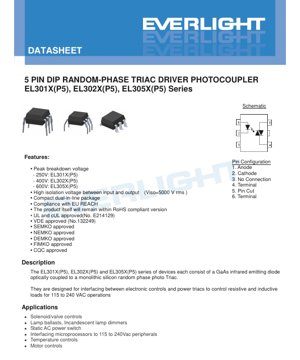
EL301X(P5), EL302X(P5) और EL305X(P5) श्रृंखला ऑप्टिकली आइसोलेटेड रैंडम-फेज़ ट्रायक ड्राइवर ऑप्टोकपलर हैं। प्रत्येक डिवाइस एक GaAs इन्फ्रारेड एलईडी और एक मोनोलिथिक सिलिकॉन रैंडम-फेज़ फोटो-ट्रायक से ऑप्टिकली युग्मित होता है। इन्हें विशेष रूप से कम वोल्टेज इलेक्ट्रॉनिक नियंत्रण सर्किट (जैसे माइक्रोकंट्रोलर या लॉजिक सर्किट) और उच्च वोल्टेज AC मेन्स-पावर्ड ट्रायक के बीच एक विश्वसनीय इंटरफेस प्रदान करने के लिए डिज़ाइन किया गया है। यह मानक 115V से 240V AC मेन्स पर काम करने वाले प्रतिरोधक और प्रेरक भार को सुरक्षित और कुशलता से नियंत्रित करने में सक्षम बनाता है। इसका मुख्य कार्य विद्युत पृथक्करण प्रदान करते हुए, एक छोटे इनपुट करंट सिग्नल को उस गेट ड्राइव सिग्नल में परिवर्तित करना है जो मुख्य पावर ट्रायक को ट्रिगर कर सके।
1.1 मुख्य लाभ एवं लक्षित बाजार
इस श्रृंखला के प्रमुख लाभों में शामिल हैं: सुरक्षा बढ़ाने के लिए उच्च पृथक्करण वोल्टेज (5000 Vrms); PCB एकीकरण के लिए सुविधाजनक कॉम्पैक्ट डुअल इन-लाइन (DIP) पैकेज; और प्रमुख अंतरराष्ट्रीय सुरक्षा मानकों (UL, cUL, VDE, SEMKO, आदि) का अनुपालन। यह उत्पाद EU REACH और RoHS निर्देशों का भी अनुपालन करता है। ये डिवाइस मुख्य रूप से उन अनुप्रयोगों के लिए हैं जिन्हें AC मेन्स पावर के सुरक्षित, पृथक नियंत्रण की आवश्यकता होती है, जो घरेलू उपकरण नियंत्रण, औद्योगिक स्वचालन, प्रकाश व्यवस्था और उपभोक्ता इलेक्ट्रॉनिक्स बाजारों की सेवा करते हैं।
2. तकनीकी मापदंडों का गहन विश्लेषण
यह खंड डेटाशीट में निर्दिष्ट प्रमुख विद्युत और प्रकाशिक मापदंडों का वस्तुनिष्ठ विश्लेषण प्रस्तुत करता है।
2.1 पूर्ण अधिकतम रेटिंग
पूर्ण अधिकतम रेटिंग उन तनाव सीमाओं को परिभाषित करती है जो डिवाइस को स्थायी क्षति पहुंचा सकती हैं। इनपुट पक्ष (LED) के लिए, अधिकतम निरंतर अग्र धारा (IF) 60 mA, अधिकतम विपरीत वोल्टेज (VR) 6 V है। इनपुट शक्ति अपव्यय (PD) 100 mW है, और 85°C से अधिक परिवेश तापमान पर, इसे 3.8 mW/°C के डिरेटिंग कारक से कम किया जाता है।
आउटपुट पक्ष (फोटो-ट्रायक) के लिए, प्रमुख पैरामीटर पीक रिपीटिटिव ऑफ-स्टेट वोल्टेज है, जो वोल्टेज अवरोधन क्षमता को परिभाषित करता है। यह श्रृंखला के अनुसार भिन्न होता है: EL301X 250V, EL302X 400V, और EL305X 600V पर रेटेड है। पीक रिपीटिटिव सर्ज करंट (ITSM) 1 A है। आउटपुट शक्ति अपव्यय (PC) 300 mW है, और 85°C से अधिक तापमान पर इसे 7.4 mW/°C की दर से डिरेट किया जाता है। डिवाइस का कुल शक्ति अपव्यय (PTOT) 330 mW से अधिक नहीं होना चाहिए। इनपुट और आउटपुट के बीच विद्युत रोधन वोल्टेज (VISO) 5000 Vrms (एक मिनट के लिए) है। संचालन तापमान सीमा -55°C से +100°C है।
2.2 प्रकाश-विद्युत विशेषताएँ
जब तक अन्यथा निर्दिष्ट न हो, ये पैरामीटर 25°C पर मापे गए हैं और विशिष्ट संचालन स्थितियों का प्रतिनिधित्व करते हैं।
2.2.1 इनपुट (LED) विशेषताएँ
इन्फ्रारेड LED का फॉरवर्ड वोल्टेज (VF) 10 mA की फॉरवर्ड करंट (IF) पर आमतौर पर 1.18V और अधिकतम 1.5V होता है। यह ड्राइव सर्किट में करंट-लिमिटिंग रेसिस्टर के डिज़ाइन के लिए महत्वपूर्ण है। 6V पूर्ण रिवर्स वोल्टेज पर, अधिकतम रिवर्स लीकेज करंट (IR) 10 µA है।
2.2.2 आउटपुट (फोटोट्रायक) विशेषताएँ
पीक ब्लॉकिंग करंट (IDRM) आउटपुट के ऑफ स्टेट में अधिकतम लीकेज करंट है, जो रेटेड VDRM और शून्य LED करंट पर अधिकतम 100 nA निर्दिष्ट है। पीक ऑन-स्टेट वोल्टेज (VTM) संचालित फोटोट्रायक के पार वोल्टेज ड्रॉप है, जो रेटेड ट्रिगर करंट पर 100 mA के पीक ऑन करंट (ITM) के दौरान अधिकतम 2.5V निर्दिष्ट है।
ट्रायक के लिए एक महत्वपूर्ण पैरामीटर क्रिटिकल ऑफ-स्टेट वोल्टेज राइज रेट (dv/dt) है। यह उपकरण की तेजी से बढ़ते वोल्टेज ट्रांजिएंट के कारण गलत ट्रिगरिंग का विरोध करने की क्षमता को दर्शाता है। EL301X और EL302X श्रृंखला का स्टैटिक dv/dt रेटिंग न्यूनतम 100 V/µs है। 400V पीक वोल्टेज पर परीक्षण किए जाने पर, EL305X श्रृंखला में काफी अधिक रेटिंग है, जो न्यूनतम 1000 V/µs है। उच्च dv/dt रेटिंग विद्युत शोर वाले वातावरण या इंडक्टिव लोड चलाते समय फायदेमंद होती है।
2.3 संचरण विशेषताएँ
ये पैरामीटर इनपुट LED करंट और आउटपुट TRIAC ट्रिगरिंग के बीच संबंध को परिभाषित करते हैं।
LED ट्रिगर करंट (IFT) आउटपुट TRIAC को चालू करने की गारंटी देने के लिए आवश्यक अधिकतम करंट है। यह श्रृंखला तीन संवेदनशीलता स्तरों में विभाजित है:
- कम संवेदनशीलता (उदाहरण के लिए, EL3010, EL3021, EL3051):अधिकतम IFT = 15 mA
- मध्यम संवेदनशीलता (उदाहरण के लिए, EL3011, EL3022, EL3052):अधिकतम IFT = 10 mA
- उच्च संवेदनशीलता (उदाहरण के लिए, EL3012, EL3023, EL3053):अधिकतम IFT = 5 mA
अनुशंसित कार्यशील LED धारा अधिकतम IFT मान और 60 mA की पूर्ण अधिकतम IF के बीच होती है। अधिकतम IFT से काफी अधिक धारा का उपयोग विश्वसनीय ट्रिगरिंग सुनिश्चित करता है, लेकिन बिजली की खपत बढ़ाता है। होल्डिंग करंट (IH) एक बार ट्रिगर होने के बाद TRIAC को संचालन में बनाए रखने के लिए आवश्यक न्यूनतम धारा है, जिसका विशिष्ट मान 250 µA है। AC चक्र के दौरान, लोड करंट इस स्तर से नीचे नहीं जाना चाहिए, अन्यथा TRIAC बंद हो जाएगा।
3. प्रदर्शन वक्र विश्लेषण
हालांकि प्रदान किए गए PDF अंश में "विशिष्ट ऑप्टोइलेक्ट्रॉनिक विशेषता वक्र" का उल्लेख है, लेकिन विशिष्ट आरेख (उदाहरण के लिए, फॉरवर्ड करंट बनाम फॉरवर्ड वोल्टेज, ट्रिगर करंट बनाम तापमान, ऑन-स्टेट वोल्टेज बनाम ऑन-स्टेट करंट) पाठ में शामिल नहीं हैं। पूर्ण डेटाशीट में, गैर-मानक स्थितियों (जैसे उच्च/निम्न तापमान) के तहत डिवाइस के व्यवहार को समझने और डिज़ाइन मार्जिन को अनुकूलित करने के लिए ये वक्र महत्वपूर्ण हैं। विस्तृत विश्लेषण के लिए डिजाइनरों को निर्माता द्वारा प्रदान किए गए पूर्ण ग्राफिकल डेटा का संदर्भ लेना चाहिए।
4. यांत्रिक एवं पैकेजिंग जानकारी
4.1 पिन कॉन्फ़िगरेशन
यह डिवाइस 6-पिन डुअल इन-लाइन पैकेज (DIP) में आता है, लेकिन कार्यात्मक रूप से 5 पिन का उपयोग करता है। पिन व्यवस्था इस प्रकार है:
- एनोड (इनपुट LED सकारात्मक टर्मिनल)
- कैथोड (LED नकारात्मक इनपुट)
- कोई कनेक्शन नहीं (N/C)
- मुख्य टर्मिनल 1 (आउटपुट TRIAC, MT1)
- पिन कट-ऑफ (यह पिन आमतौर पर यांत्रिक संरेखण के लिए काटा जाता है या नहीं लगाया जाता है)
- मुख्य टर्मिनल 2 (आउटपुट TRIAC, MT2)
अलगाव वोल्टेज परीक्षण के दौरान, पिन 1, 2 और 3 को एक साथ शॉर्ट किया जाता है, जबकि पिन 4 और 6 को एक साथ शॉर्ट किया जाता है, जिससे अलगाव बैरियर को स्पष्ट रूप से परिभाषित किया जाता है।
4.2 पैकेजिंग विकल्प एवं आयाम
मानक पैकेज थ्रू-होल DIP-6 है। डेटाशीट कई पिन फॉर्म और पैकेजिंग विकल्प भी सूचीबद्ध करती है:
- नहीं/M:मानक या चौड़े पिन बेंड के साथ थ्रू-होल संस्करण, ट्यूब में पैक, प्रति ट्यूब 65 टुकड़े।
- S / S1 (TA/TB):सरफेस माउंट पिन फॉर्म। 'S1' पतले संस्करण को दर्शाता है। 'TA' और 'TB' विभिन्न टेपिंग विनिर्देशों को संदर्भित करते हैं। ये रील पर आपूर्ति की जाती हैं, प्रति रील 1000 टुकड़े।
सटीक यांत्रिक आयामों के लिए, जिसमें बॉडी लंबाई, चौड़ाई, ऊंचाई और पिन पिच शामिल हैं, डिजाइनरों को एक अलग पैकेज आउटलाइन ड्राइंग का संदर्भ लेना चाहिए जो इस पाठ अंश में शामिल नहीं है।
5. सोल्डरिंग एवं असेंबली मार्गदर्शिका
सोल्डरिंग तापमान (TSOL) का पूर्ण अधिकतम रेटिंग 260°C है, 10 सेकंड के लिए। यह वेव सोल्डरिंग (थ्रू-होल घटकों) और रीफ्लो सोल्डरिंग (सरफेस माउंट घटकों) दोनों के लिए एक महत्वपूर्ण पैरामीटर है। रीफ्लो प्रोफाइल का उपयोग करते समय, आंतरिक चिप और प्लास्टिक पैकेज को नुकसान से बचाने के लिए, पीक तापमान और लिक्विडस से ऊपर के समय को इस सीमा के भीतर नियंत्रित किया जाना चाहिए। लीड-फ्री असेंबली के लिए मानक उद्योग रीफ्लो प्रोफाइल (जैसे, IPC/JEDEC J-STD-020) का इस 260°C सीमा के संबंध में मूल्यांकन किया जाना चाहिए। भंडारण की स्थिति -55°C से +125°C निर्धारित है।
6. ऑर्डर जानकारी और मॉडल नामकरण
पार्ट नंबर एक संरचित प्रारूप का पालन करता है:EL30[1/2/5]XY(Z)(P5)-V
- पहला अंक (श्रृंखला/वोल्टेज):1=250V, 2=400V, 5=600V.
- दूसरा अंक (X - संवेदनशीलता स्तर):EL301x के लिए: 0,1,2। EL302x/EL305x के लिए: 1,2,3। संख्या जितनी छोटी होगी, संवेदनशीलता उतनी ही कम होगी (IFT उतना ही अधिक होगा)।
- तीसरा वर्ण (Y - पिन प्रकार):S (SMD), S1 (लो-प्रोफाइल SMD), M (वाइड बेंड) या कोई नहीं (मानक DIP)।
- चौथा वर्ण (Z - टेप/रील):TA या TB (रील विशिष्टता), या कोई नहीं।
- (P5):5-पिन प्रकार को दर्शाता है।
- -V (वैकल्पिक):VDE सुरक्षा प्रमाणन होने का संकेत देता है।
उदाहरण:EL3022S(TA)(P5) एक 400V, मध्यम संवेदनशीलता (IFT 10mA), TA टेप और रील के साथ सतह माउंट डिवाइस है।
7. अनुप्रयोग सुझाव
7.1 टाइपिकल एप्लीकेशन सर्किट
इसका मुख्य अनुप्रयोग मुख्य पावर TRIAC के लिए एक पृथक गेट ड्राइवर के रूप में है। एक विशिष्ट सर्किट में माइक्रोकंट्रोलर GPIO पिन करंट-लिमिटिंग रेसिस्टर (Rlimit) के माध्यम से ऑप्टोकपलर के LED को ड्राइव करता है। गणना सूत्र है Rlimit = (Vcc - VF) / IF, जहां विश्वसनीयता सुनिश्चित करने के लिए IF को IFT(max) और 60mA के बीच चुना जाना चाहिए। ऑप्टोकपलर के आउटपुट टर्मिनल (MT1/MT2) मुख्य TRIAC के गेट और एक छोटे गेट रेसिस्टर के साथ श्रृंखला में जुड़े होते हैं। ऑप्टोकपलर का आउटपुट सीधे मुख्य TRIAC के MT1 और गेट टर्मिनलों के बीच जुड़ा होता है।
7.2 डिज़ाइन विचार और सर्वोत्तम अभ्यास
1. लोड प्रकार:ये उपकरण इसके लिए डिज़ाइन किए गए हैंरैंडम फेज़नियंत्रण, जिसका अर्थ है कि इन्हें एसी वोल्टेज चक्र के किसी भी बिंदु पर मुख्य TRIAC को ट्रिगर करने के लिए सक्रिय किया जा सकता है। यह प्रतिरोधक भार (हीटर, गरमागरम लैंप) और कुछ प्रेरक भार (सोलेनॉइड, मोटर स्टार्टर) के लिए उपयुक्त है। प्रेरक भार के लिए, dv/dt को सीमित करने और गलत ट्रिगरिंग या कम्यूटेशन विफलता को रोकने के लिए मुख्य TRIAC के पार एक स्नबर नेटवर्क (RC सर्किट) लगाना लगभग हमेशा आवश्यक होता है।
2. वोल्टेज चयन:वोल्टेज रेटिंग (EL301X/302X/305X) का चयन करें ताकि यह एसी लाइन के शिखर वोल्टेज से अधिक हो और एक सुरक्षा मार्जिन बचा रहे। 240VAC लाइन (लगभग 340V शिखर) के लिए, 400V (EL302X) या 600V (EL305X) श्रृंखला का उपयोग करना चाहिए।
3. संवेदनशीलता चयन:उच्च संवेदनशीलता वाले घटक (कम IFT) नियंत्रण सर्किट के लिए आवश्यक ड्राइव करंट को कम करते हैं, जो बैटरी से चलने वाले या कम बिजली खपत वाले लॉजिक सर्किट के लिए फायदेमंद है। हालांकि, वे इनपुट साइड के शोर के प्रति थोड़ा अधिक संवेदनशील हो सकते हैं।
4. dv/dt विचार:विद्युत शोर वाले वातावरण या उच्च प्रेरक भार के मामलों में, उच्च dv/dt रेटिंग वाले घटक चुनें (EL305X 1000 V/µs प्रदान करता है)। सुनिश्चित करें कि मुख्य TRIAC के पार स्नबर सर्किट उचित रूप से डिज़ाइन किया गया है ताकि लागू dv/dt ऑप्टोकपलर की रेटिंग से कम रहे।
5. थर्मल प्रबंधन:इनपुट LED (Pled = VF * IF) और आउटपुट TRIAC (Ptriac ≈ VTM * Iload(rms) * ड्यूटी साइकिल, जहां ड्यूटी साइकिल कम है क्योंकि यह केवल गेट करंट चालू करता है) की बिजली अपव्यय की गणना करें। सुनिश्चित करें कि एप्लिकेशन तापमान डेरेटिंग के बाद, कुल बिजली अपव्यय PTOT (330 mW) से अधिक न हो।
8. तकनीकी तुलना और विभेदीकरण
इस श्रृंखला के भीतर मुख्य अंतर ब्लॉकिंग वोल्टेज और ट्रिगर संवेदनशीलता के संयोजन में निहित है। EL305X श्रृंखला उच्चतम वोल्टेज रेटिंग (600V) और उच्चतम स्थिर dv/dt प्रतिरक्षा (1000 V/µs) प्रदान करती है, जो इसे अधिक मांग वाले औद्योगिक वातावरण के लिए उपयुक्त बनाती है। जीरो-क्रॉसिंग ऑप्टोकपलर की तुलना में, इस श्रृंखला जैसे रैंडम फेज़ ड्राइवर फेज़ एंगल नियंत्रण की अनुमति देते हैं, जिससे गरमागरम लैंप डिमिंग और मोटर सॉफ्ट-स्टार्ट जैसे अनुप्रयोग सक्षम होते हैं, जो जीरो-क्रॉसिंग प्रकार द्वारा प्राप्त नहीं किए जा सकते।
9. सामान्य प्रश्न (तकनीकी मापदंडों पर आधारित)
Q1: क्या मैं इसका उपयोग सीधे 1A के लोड को स्विच करने के लिए कर सकता हूं?
A: नहीं। आउटपुट फोटोट्रायक का रेटेड पीक सर्ज करंट (ITSM) केवल 1A है, जिसे डिज़ाइन किया गया हैअधिक शक्तिशाली ट्रायक के गेट को ड्राइव करने के लिए, न कि लोड को सीधे ड्राइव करने के लिए। मुख्य पावर ट्रायक लोड करंट को संभालता है।
Q2: मेरी लाइन वोल्टेज 120VAC है। क्या मुझे 600V के पार्ट की आवश्यकता है?
A: जरूरी नहीं। 250V रेटेड EL301X में 250V की पीक वोल्टेज क्षमता है, जो 120VAC के पीक (लगभग 170V) से अधिक है। हालांकि, सुरक्षा मार्जिन और मेन्स पर वोल्टेज स्पाइक्स/ट्रांजिएंट्स को ध्यान में रखते हुए, 120VAC अनुप्रयोगों के लिए 400V का EL302X एक अधिक मजबूत और आमतौर पर अनुशंसित विकल्प है।
Q3: अगर मैं LED को लगातार 50mA से ड्राइव करता हूं तो क्या होगा?
A: यह पूर्ण अधिकतम रेटिंग (60mA) के भीतर है, लेकिन आमतौर पर आवश्यक ट्रिगर करंट से अधिक है। यह काम करेगा, लेकिन इनपुट पावर डिसिपेशन (Pled) को बढ़ा देगा। आपको यह सुनिश्चित करना होगा कि डिवाइस का कुल पावर डिसिपेशन (Pled + Ptriac) रेटेड PTOT के भीतर रहे, खासकर उच्च तापमान वातावरण में डीरेटिंग के बाद।
Q4: dv/dt परीक्षण सर्किट जटिल दिखता है। मैं कैसे सुनिश्चित करूं कि मेरा डिज़ाइन आवश्यकताओं को पूरा करता है?
A: अधिकांश डिज़ाइनों के लिए, मुख्य पावर TRIAC के पार अनुशंसित स्नबर सर्किट (उदाहरण के लिए, एक 100Ω रोकनेवाला श्रृंखला में 0.1µF संधारित्र के साथ) का उपयोग करना(ऑप्टोकपलर नहीं), मुख्य TRIAC और ऑप्टोकपलर आउटपुट द्वारा देखे गए वोल्टेज वृद्धि दर को सीमित करने के लिए पर्याप्त है, जिससे उनकी सुरक्षा होती है।
10. व्यावहारिक डिज़ाइन केस स्टडी
परिदृश्य:3.3V माइक्रोकंट्रोलर द्वारा नियंत्रित 120VAC, 500W तापदीप्त लैंप डिमर डिज़ाइन करें।
चरण:
- वोल्टेज रेटिंग:120VAC पीक (लगभग 170V) से ऊपर मार्जिन रखने के लिए EL302X (400V) का चयन करें।
- संवेदनशीलता:MCU की करंट खपत को न्यूनतम करने के लिए EL3023 (उच्च संवेदनशीलता, IFTmax=5mA) का चयन करें।
- LED रेसिस्टर गणना:मान लें VFtyp=1.18V। लक्ष्य IF=8mA (5mA IFT से अधिक)। Rlimit = (3.3V - 1.18V) / 0.008A ≈ 265Ω। मानक 270Ω रेसिस्टर का उपयोग करें। R पर पावर डिसिपेशन: (3.3-1.18)^2/270 ≈ 0.017W (अच्छा)।
- मुख्य TRIAC चयन:120VAC से अधिक 500W रेटिंग वाला एक द्विदिश थाइरिस्टर चुनें (उदाहरण के लिए, 8A, 600V)।
- गेट सर्किट:ऑप्टोकपलर पिन 4 और 6 को एक 100-330Ω गेट रेसिस्टर के साथ श्रृंखला में जोड़कर मुख्य द्विदिश थाइरिस्टर के गेट से कनेक्ट करें।
- स्नबर:मुख्य द्विदिश थाइरिस्टर के MT1 और MT2 टर्मिनलों के पार एक RC स्नबर (उदाहरण के लिए, 100Ω, 0.1µF, 250VAC रेटेड) लगाएं।
- माइक्रोकंट्रोलर कोड:एक फेज एंगल कंट्रोल एल्गोरिदम लागू करें, जो टाइमर इंटरप्ट का उपयोग करके, AC लाइन जीरो-क्रॉसिंग (दूसरे सर्किट द्वारा पता लगाए जाने के बाद) पर एक परिवर्तनशील विलंब के बाद ऑप्टोकपलर के LED को ट्रिगर करे।
11. कार्य सिद्धांत
यह उपकरण ऑप्टिकल इंसुलेशन के सिद्धांत पर कार्य करता है। जब इनपुट इन्फ्रारेड लाइट एमिटिंग डायोड (LED) पर पर्याप्त फॉरवर्ड करंट लगाया जाता है, तो यह फोटॉन उत्सर्जित करता है। ये फोटॉन आंतरिक इंसुलेशन गैप को पार करके आउटपुट साइड पर एकीकृत सिलिकॉन फोटोसेंसिटिव ट्रायक के प्रकाश-संवेदनशील क्षेत्र पर पड़ते हैं। यह प्रकाश ऊर्जा चार्ज वाहक उत्पन्न करती है, जो थाइरिस्टर (ट्रायक) संरचना को संचालन अवस्था में ट्रिगर करती है, जिससे इसके दो मुख्य टर्मिनलों (MT1 और MT2) के बीच स्विच प्रभावी रूप से बंद हो जाता है। मुख्य बात यह है कि यह ट्रिगर क्रिया इनपुट और आउटपुट के बीच किसी भी विद्युत कनेक्शन के बिना प्राप्त की जाती है, जो विद्युत इंसुलेशन की सुरक्षा और शोर प्रतिरोध प्रदान करती है। "रैंडम फेज" क्षमता का अर्थ है कि यह ट्रिगरिंग आउटपुट पर लागू एसी वेवफॉर्म के किसी भी तात्कालिक वोल्टेज स्तर पर हो सकती है।
12. प्रौद्योगिकी रुझान
ऑप्टोकपलर तकनीक का निरंतर विकास जारी है। ट्रायक ड्राइवरों से संबंधित रुझानों में शामिल हैं: अधिक उन्नत सुरक्षा सुविधाओं (जैसे ओवरकरंट डिटेक्शन या थर्मल शटडाउन) को सीधे IC में एकीकृत करना; उच्च विश्वसनीयता और लंबे परिचालन जीवन की खोज, विशेष रूप से LED एमिटर के लिए; इसके अलावा, लघुकरण की आवश्यकता छोटे सतह माउंट पैकेज (जैसे इस श्रृंखला में S1 पतला विकल्प) को अपनाने को बढ़ावा दे रही है, जबकि इंसुलेशन रेटिंग बनाए रखना या बेहतर बनाना; सभी इलेक्ट्रॉनिक सिस्टम में उच्च दक्षता की ओर रुझान कम ट्रिगर करंट (उच्च संवेदनशीलता) और कम ऑन-स्टेट वोल्टेज वाले डिजाइनों को अपनाने के लिए प्रोत्साहित करता है, ताकि समग्र सिस्टम पावर लॉस कम हो।
LED विनिर्देश शब्दावली विस्तृत व्याख्या
LED Technical Terms Complete Explanation
1. प्रकाश-विद्युत प्रदर्शन मुख्य संकेतक
| Terminology | इकाई/प्रतिनिधित्व | सामान्य व्याख्या | यह महत्वपूर्ण क्यों है |
|---|---|---|---|
| दीप्त प्रभावकारिता (Luminous Efficacy) | lm/W (लुमेन प्रति वाट) | प्रति वाट विद्युत ऊर्जा से उत्सर्जित प्रकाश प्रवाह, जितना अधिक होगा उतनी ही अधिक ऊर्जा दक्षता। | सीधे लैंप की ऊर्जा दक्षता रेटिंग और बिजली लागत निर्धारित करता है। |
| ल्यूमिनस फ्लक्स (Luminous Flux) | lm (लुमेन) | प्रकाश स्रोत द्वारा उत्सर्जित प्रकाश की कुल मात्रा, जिसे आमतौर पर "चमक" कहा जाता है। | यह निर्धारित करता है कि लैंप पर्याप्त रूप से चमकीला है या नहीं। |
| दृश्य कोण (Viewing Angle) | ° (डिग्री), जैसे 120° | प्रकाश तीव्रता आधी रह जाने पर का कोण, जो बीम की चौड़ाई निर्धारित करता है। | प्रकाश के विस्तार और एकरूपता को प्रभावित करता है। |
| रंग तापमान (CCT) | K (केल्विन), जैसे 2700K/6500K | प्रकाश के रंग की गर्माहट या ठंडक, कम मान पीला/गर्म, अधिक मान सफेद/ठंडा। | प्रकाश व्यवस्था का माहौल और उपयुक्त परिदृश्य निर्धारित करता है। |
| कलर रेंडरिंग इंडेक्स (CRI / Ra) | इकाई रहित, 0–100 | प्रकाश स्रोत द्वारा वस्तुओं के वास्तविक रंगों को प्रदर्शित करने की क्षमता, Ra≥80 उत्तम माना जाता है। | रंग की वास्तविकता को प्रभावित करता है, शॉपिंग मॉल, आर्ट गैलरी जैसे उच्च आवश्यकता वाले स्थानों में प्रयुक्त। |
| क्रोमैटिसिटी टॉलरेंस (SDCM) | मैकएडम अंडाकार चरण संख्या, जैसे "5-step" | रंग एकरूपता का मात्रात्मक मापक, चरण संख्या जितनी कम होगी रंग उतने ही अधिक सुसंगत होंगे। | एक ही बैच के दीपकों के रंग में कोई अंतर न हो, यह सुनिश्चित करना। |
| प्रमुख तरंगदैर्ध्य (Dominant Wavelength) | nm (नैनोमीटर), जैसे 620nm (लाल) | रंगीन LED के रंग से संबंधित तरंगदैर्ध्य मान। | लाल, पीले, हरे आदि मोनोक्रोमैटिक एलईडी के रंग टोन को निर्धारित करता है। |
| स्पेक्ट्रम वितरण (Spectral Distribution) | तरंगदैर्ध्य बनाम तीव्रता वक्र | एलईडी द्वारा उत्सर्जित प्रकाश की विभिन्न तरंगदैर्ध्य पर तीव्रता वितरण को प्रदर्शित करता है। | रंग प्रतिपादन और रंग गुणवत्ता को प्रभावित करता है। |
2. विद्युत मापदंड
| Terminology | प्रतीक | सामान्य व्याख्या | डिज़ाइन विचार |
|---|---|---|---|
| फॉरवर्ड वोल्टेज (Forward Voltage) | Vf | LED को चालू करने के लिए आवश्यक न्यूनतम वोल्टेज, एक "स्टार्ट-अप थ्रेशोल्ड" के समान। | ड्राइवर पावर सप्लाई वोल्टेज ≥ Vf होना चाहिए, कई LEDs को श्रृंखला में जोड़ने पर वोल्टेज जुड़ जाता है। |
| फॉरवर्ड करंट (Forward Current) | If | एलईडी को सामान्य रूप से चमकने के लिए आवश्यक करंट मान। | आमतौर पर कॉन्स्टेंट करंट ड्राइव का उपयोग किया जाता है, करंट चमक और आयु निर्धारित करता है। |
| अधिकतम पल्स करंट (Pulse Current) | Ifp | अल्प समय में सहन करने योग्य चरम धारा, डिमिंग या फ्लैश के लिए। | पल्स चौड़ाई और ड्यूटी साइकिल को सख्ती से नियंत्रित किया जाना चाहिए, अन्यथा अत्यधिक गर्मी से क्षति हो सकती है। |
| रिवर्स वोल्टेज (Reverse Voltage) | Vr | LED द्वारा सहन की जा सकने वाली अधिकतम रिवर्स वोल्टेज, इससे अधिक होने पर ब्रेकडाउन हो सकता है। | सर्किट में रिवर्स कनेक्शन या वोल्टेज स्पाइक से बचाव आवश्यक है। |
| थर्मल रेजिस्टेंस (Thermal Resistance) | Rth (°C/W) | चिप से सोल्डर पॉइंट तक गर्मी के प्रवाह में प्रतिरोध, कम मान बेहतर हीट डिसिपेशन दर्शाता है। | उच्च थर्मल रेजिस्टेंस के लिए मजबूत हीट सिंक डिज़ाइन की आवश्यकता होती है, अन्यथा जंक्शन तापमान बढ़ जाता है। |
| इलेक्ट्रोस्टैटिक डिस्चार्ज इम्यूनिटी (ESD Immunity) | V (HBM), जैसे 1000V | एंटीस्टैटिक शॉक प्रतिरोध, उच्च मान स्थैतिक बिजली क्षति के प्रति कम संवेदनशीलता दर्शाता है। | उत्पादन में एंटीस्टैटिक सुरक्षा उपाय आवश्यक हैं, विशेष रूप से उच्च संवेदनशीलता वाले एलईडी के लिए। |
तीन, ताप प्रबंधन और विश्वसनीयता
| Terminology | प्रमुख संकेतक | सामान्य व्याख्या | प्रभाव |
|---|---|---|---|
| जंक्शन तापमान (Junction Temperature) | Tj (°C) | एलईडी चिप का आंतरिक वास्तविक कार्य तापमान। | प्रत्येक 10°C कमी पर, जीवनकाल दोगुना हो सकता है; अत्यधिक तापमान से ल्यूमेन ह्रास और रंग विस्थापन होता है। |
| ल्यूमेन डिप्रिसिएशन (Lumen Depreciation) | L70 / L80 (घंटे) | चमक प्रारंभिक मान के 70% या 80% तक गिरने में लगने वाला समय। | एलईडी की "सेवा जीवन" को सीधे परिभाषित करें। |
| लुमेन रखरखाव (Lumen Maintenance) | % (जैसे 70%) | एक निश्चित अवधि के उपयोग के बाद शेष चमक का प्रतिशत। | दीर्घकालिक उपयोग के बाद चमक बनाए रखने की क्षमता को दर्शाता है। |
| रंग परिवर्तन (Color Shift) | Δu′v′ या मैकएडम एलिप्स | उपयोग के दौरान रंग में परिवर्तन की मात्रा। | प्रकाश व्यवस्था के दृश्य की रंग एकरूपता को प्रभावित करता है। |
| थर्मल एजिंग (Thermal Aging) | सामग्री प्रदर्शन में गिरावट | दीर्घकालिक उच्च तापमान के कारण एनकैप्सुलेशन सामग्री का क्षरण। | इससे चमक में कमी, रंग परिवर्तन या ओपन-सर्किट विफलता हो सकती है। |
चार, पैकेजिंग और सामग्री
| Terminology | सामान्य प्रकार | सामान्य व्याख्या | विशेषताएँ एवं अनुप्रयोग |
|---|---|---|---|
| पैकेजिंग प्रकार | EMC, PPA, सिरेमिक | चिप की सुरक्षा करने वाली और प्रकाशिक एवं ऊष्मीय इंटरफेस प्रदान करने वाली आवरण सामग्री। | EMC उच्च ताप सहनशीलता, कम लागत; सिरेमिक बेहतर ताप अपव्यय, लंबी आयु। |
| चिप संरचना | फॉरवर्ड माउंट, फ्लिप चिप (Flip Chip) | चिप इलेक्ट्रोड व्यवस्था विधि। | फ्लिप चिप बेहतर ताप अपव्यय, उच्च प्रकाश दक्षता, उच्च शक्ति के लिए उपयुक्त। |
| फॉस्फर कोटिंग | YAG, सिलिकेट, नाइट्राइड | ब्लू LED चिप पर लगाया जाता है, जो प्रकाश के एक भाग को पीली/लाल रोशनी में परिवर्तित करता है और सफेद प्रकाश बनाने के लिए मिलाया जाता है। | विभिन्न फॉस्फर दक्षता, कलर टेम्परेचर और कलर रेंडरिंग को प्रभावित करते हैं। |
| लेंस/ऑप्टिकल डिज़ाइन | प्लेन, माइक्रोलेंस, टोटल इंटरनल रिफ्लेक्शन | पैकेजिंग सतह की प्रकाशिक संरचना, प्रकाश वितरण को नियंत्रित करती है। | उत्सर्जन कोण और प्रकाश वितरण वक्र निर्धारित करता है। |
पाँच, गुणवत्ता नियंत्रण और ग्रेडिंग
| Terminology | ग्रेडिंग सामग्री | सामान्य व्याख्या | उद्देश्य |
|---|---|---|---|
| लुमेन आउटपुट ग्रेडिंग | कोड जैसे 2G, 2H | चमक के स्तर के अनुसार समूहीकरण, प्रत्येक समूह का न्यूनतम/अधिकतम लुमेन मान होता है। | यह सुनिश्चित करें कि एक ही बैच के उत्पादों की चमक समान हो। |
| वोल्टेज ग्रेडिंग | कोड जैसे 6W, 6X | फॉरवर्ड वोल्टेज रेंज के अनुसार समूहीकरण। | ड्राइविंग पावर मिलान की सुविधा, सिस्टम दक्षता में सुधार। |
| रंग विभेदीकरण ग्रेडिंग | 5-step MacAdam ellipse | रंग निर्देशांक के अनुसार समूहीकरण, यह सुनिश्चित करना कि रंग अत्यंत सीमित सीमा के भीतर रहें। | रंग एकरूपता सुनिश्चित करना, एक ही ल्यूमिनेयर के भीतर रंग असमानता से बचना। |
| कलर टेम्परेचर ग्रेडिंग | 2700K, 3000K, इत्यादि | रंग तापमान के अनुसार समूहीकृत, प्रत्येक समूह की संबंधित निर्देशांक सीमा होती है। | विभिन्न परिदृश्यों की रंग तापमान आवश्यकताओं को पूरा करना। |
छह, परीक्षण और प्रमाणन
| Terminology | मानक/परीक्षण | सामान्य व्याख्या | महत्व |
|---|---|---|---|
| LM-80 | ल्यूमेन रखरखाव परीक्षण | निरंतर तापमान परिस्थितियों में लंबे समय तक जलाकर, चमक क्षय डेटा रिकॉर्ड किया जाता है। | एलईडी जीवनकाल का अनुमान लगाने के लिए (TM-21 के साथ संयोजन में)। |
| TM-21 | जीवनकाल प्रक्षेपण मानक | LM-80 डेटा के आधार पर वास्तविक उपयोग की स्थितियों में जीवनकाल का अनुमान लगाना। | वैज्ञानिक जीवनकाल पूर्वानुमान प्रदान करना। |
| IESNA मानक | इल्युमिनेटिंग इंजीनियरिंग सोसाइटी मानक | प्रकाशिक, विद्युत और ऊष्मा परीक्षण विधियों को शामिल करना। | उद्योग द्वारा स्वीकृत परीक्षण आधार। |
| RoHS / REACH | पर्यावरण प्रमाणन | उत्पाद हानिकारक पदार्थों (जैसे सीसा, पारा) से मुक्त होने की पुष्टि करें। | अंतरराष्ट्रीय बाजार में प्रवेश के लिए पात्रता शर्तें। |
| ENERGY STAR / DLC | ऊर्जा दक्षता प्रमाणन | प्रकाश उत्पादों के लिए ऊर्जा दक्षता और प्रदर्शन प्रमाणन। | सामान्यतः सरकारी खरीद, सब्सिडी परियोजनाओं में उपयोग किया जाता है, बाजार प्रतिस्पर्धा बढ़ाने के लिए। |