सामग्री
- 1. उत्पाद अवलोकन
- 2. गहन तकनीकी मापदंड विश्लेषण
- 2.1 पूर्ण अधिकतम रेटिंग
- 2.2 ऑप्टोइलेक्ट्रॉनिक विशेषताएँ
- 3. ग्रेडिंग प्रणाली विवरण
- 3.1 ल्यूमिनस तीव्रता ग्रेडिंग
- 3.2 प्रमुख तरंगदैर्ध्य ग्रेडिंग
- 3.3 फॉरवर्ड वोल्टेज ग्रेडिंग
- 4. प्रदर्शन वक्र विश्लेषण
- 5. यांत्रिक और पैकेजिंग जानकारी
- 5.1 पैकेज आयाम
- 5.2 स्वचालित संयोजन पैकेजिंग
- 6. सोल्डरिंग और संयोजन मार्गदर्शिका
- 6.1 भंडारण और नमी संवेदनशीलता
- 6.2 रीफ्लो सोल्डरिंग तापमान प्रोफाइल
- 6.3 हैंड सोल्डरिंग और रिपेयर
- 7. पैकेजिंग और ऑर्डर जानकारी
- 8. अनुप्रयोग सुझाव
- 8.1 विशिष्ट अनुप्रयोग परिदृश्य
- 8.2 प्रमुख डिज़ाइन विचार
- 9. तकनीकी तुलना और विभेदीकरण
- 10. अक्सर पूछे जाने वाले प्रश्न (FAQ)
- 10.1 करंट-लिमिटिंग रेसिस्टर क्यों बिल्कुल आवश्यक है?
- 10.2 क्या मैं इस LED को सीधे 3.3V या 5V लॉजिक पावर स्रोत से चला सकता हूँ?
- 10.3 बिनिंग कोड (P1, CC4, 21) का मेरे डिज़ाइन के लिए क्या अर्थ है?
- 10.4 मॉइस्चर बैरियर बैग खोलने के बाद की 7-दिन की फ्लोर लाइफ कितनी महत्वपूर्ण है?
- 11. व्यावहारिक डिज़ाइन एवं उपयोग केस
- 12. कार्य सिद्धांत
- 13. तकनीकी रुझान एवं पृष्ठभूमि
- LED विनिर्देश शब्दावली का विस्तृत विवरण
- 1. प्रकाश-विद्युत प्रदर्शन के मुख्य संकेतक
- 2. विद्युत मापदंड
- 3. ताप प्रबंधन और विश्वसनीयता
- चार, पैकेजिंग और सामग्री
- पाँच, गुणवत्ता नियंत्रण और ग्रेडिंग
- छह, परीक्षण और प्रमाणन
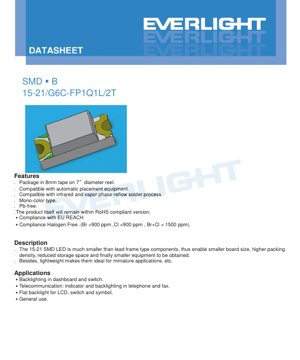
1. उत्पाद अवलोकन
15-21/G6C-FP1Q1L/2T आधुनिक कॉम्पैक्ट इलेक्ट्रॉनिक अनुप्रयोगों के लिए विशेष रूप से डिज़ाइन किया गया एक सरफेस माउंट डिवाइस (एसएमडी) एलईडी है। पारंपरिक लीड फ्रेम एलईडी की तुलना में, यह घटक पैकेज आकार और वजन में उल्लेखनीय कमी प्रदर्शित करता है, जो तकनीकी प्रगति का प्रतिनिधित्व करता है। इसका प्राथमिक कार्य एक सूक्ष्म पैकेज के भीतर एक विश्वसनीय और कुशल प्रकाश स्रोत प्रदान करना है, जिससे प्रिंटेड सर्किट बोर्ड (पीसीबी) पर उच्च घटक घनत्व प्राप्त हो और इलेक्ट्रॉनिक उपकरणों के समग्र लघुरूपण में सहायता मिले। मॉडल नंबर में "G6C" पहचानकर्ता इंगित करता है कि यह आंतरिक रूप से AlGaInP (एल्युमिनियम गैलियम इंडियम फॉस्फाइड) अर्धचालक सामग्री का उपयोग करता है और एक वाटर क्लियर रेजिन लेंस के साथ एनकैप्सुलेटेड है, जो एक विशिष्ट चमकीले पीले-हरे प्रकाश का उत्सर्जन करता है।
इस एलईडी का मुख्य लाभ इसकी एसएमडी संरचना से प्राप्त होता है। लीडलेस डिज़ाइन परजीवी प्रेरकत्व को कम करता है और स्वचालित पिक एंड प्लेस असेंबली का समर्थन करता है, जिससे बड़े पैमाने पर निर्माण प्रक्रिया सरल हो जाती है। इसका छोटा आकार (लगभग 1.6mm x 0.8mm x 0.6mm) सीधे तौर पर भंडारण स्थान की आवश्यकता को कम करता है और अंतिम उत्पादों को पतले डिज़ाइन करने की अनुमति देता है। इसके अलावा, यह उत्पाद प्रमुख पर्यावरणीय और सुरक्षा नियमों का अनुपालन करता है, जिसमें लीड-फ्री, RoHS अनुपालन, REACH अनुपालन और हैलोजन-फ्री विशेषताएं शामिल हैं, जो वैश्विक इलेक्ट्रॉनिक बाजार की कठोर मांगों को पूरा करती हैं।
2. गहन तकनीकी मापदंड विश्लेषण
एलईडी का प्रदर्शन और सीमाएं उसके विद्युत, प्रकाशिक और तापीय विनिर्देशों द्वारा परिभाषित होती हैं। विश्वसनीय सर्किट डिज़ाइन और दीर्घकालिक प्रदर्शन सुनिश्चित करने के लिए इन मापदंडों की गहन समझ महत्वपूर्ण है।
2.1 पूर्ण अधिकतम रेटिंग
ये रेटिंग उन तनाव सीमाओं को परिभाषित करती हैं जो डिवाइस को स्थायी क्षति पहुंचा सकती हैं। इन सीमाओं पर या उससे अधिक पर संचालन की कोई गारंटी नहीं है।
- रिवर्स वोल्टेज (VR):5V। रिवर्स बायस में इस वोल्टेज से अधिक होने पर जंक्शन ब्रेकडाउन हो सकता है।
- कंटीन्यूअस फॉरवर्ड करंट (IF):25mA। यह 25°C पर निरंतर संचालन के लिए अनुशंसित अधिकतम डीसी करंट है।
- पीक फॉरवर्ड करंट (IFP):60mA। यह करंट केवल पल्स स्थितियों (ड्यूटी साइकिल 1/10, फ्रीक्वेंसी 1kHz) में अनुमत है, और अल्पकालिक उच्च चमक प्राप्त करने के लिए उपयोग किया जा सकता है।
- पावर डिसिपेशन (Pd):60mW। यह वह अधिकतम शक्ति है जिसे पैकेज ऊष्मा के रूप में अपव्ययित कर सकता है, जिसकी गणना VF * IF सूत्र द्वारा की जाती है।
- इलेक्ट्रोस्टैटिक डिस्चार्ज (ESD):2000V (ह्यूमन बॉडी मॉडल)। यह रेटिंग इंगित करती है कि डिवाइस में मध्यम ESD संवेदनशीलता है; उचित हैंडलिंग प्रक्रियाओं का पालन किया जाना चाहिए।
- ऑपरेटिंग एवं स्टोरेज तापमान:-40°C से +85°C (ऑपरेटिंग), -40°C से +90°C (स्टोरेज)। विस्तृत तापमान सीमा इसे विभिन्न पर्यावरणीय परिस्थितियों के लिए उपयुक्त बनाती है।
- सोल्डरिंग तापमान:260°C रिफ्लो सोल्डरिंग के लिए 10 सेकंड, या प्रति पिन 350°C हैंड सोल्डरिंग के लिए 3 सेकंड तक सहन कर सकता है।
2.2 ऑप्टोइलेक्ट्रॉनिक विशेषताएँ
ये 20mA के फॉरवर्ड करंट (IF) और 25°C के एंबिएंट टेम्परेचर (Ta) पर मापे गए टाइपिकल परफॉर्मेंस पैरामीटर्स हैं।
- ल्यूमिनस इंटेंसिटी (Iv):रेंज 45.0 mcd (न्यूनतम) से 90.0 mcd (अधिकतम) तक है, जिसका टाइपिकल टॉलरेंस ±11% है। यह अनुभूत चमक को परिभाषित करता है।
- व्यूइंग एंगल (2θ1/2):130 डिग्री (टाइपिकल)। चौड़ा व्यूइंग एंगल एक विस्तृत उत्सर्जन पैटर्न प्रदान करता है, जो एरिया लाइटिंग और इंडिकेटर एप्लीकेशन के लिए उपयुक्त है।
- पीक वेवलेंथ (λp):575 nm (टाइपिकल)। यह वह वेवलेंथ है जिस पर स्पेक्ट्रल पावर डिस्ट्रीब्यूशन अपने अधिकतम मान तक पहुंचता है।
- डोमिनेंट वेवलेंथ (λd):सीमा 570.0 nm से 574.5 nm तक। यह मानव आँख द्वारा अनुभव किया जाने वाला एकवर्णी तरंगदैर्ध्य है, जो रंग की आभा (चमकीला पीला-हरा) को परिभाषित करता है। सहनशीलता ±1nm है।
- स्पेक्ट्रल बैंडविड्थ (Δλ):20 nm (विशिष्ट)। यह अर्ध-अधिकतम तीव्रता पर उत्सर्जन स्पेक्ट्रम की चौड़ाई है।
- फॉरवर्ड वोल्टेज (VF):20mA पर, सीमा 1.70V से 2.30V तक, विशिष्ट सहनशीलता ±0.05V है। यह LED के चालू होने पर इसके सिरों पर वोल्टेज ड्रॉप है।
- रिवर्स करंट (IR):VR=5V पर, अधिकतम 10 μA। यह उपकरण रिवर्स ऑपरेशन के लिए डिज़ाइन नहीं किया गया है; यह पैरामीटर केवल लीकेज करंट परीक्षण के लिए है।
3. ग्रेडिंग प्रणाली विवरण
अर्धचालक निर्माण में निहित विविधताओं के कारण, एलईडी को उनके प्रदर्शन के आधार पर बिन किया जाता है। यह प्रणाली डिजाइनरों को उनके अनुप्रयोग की स्थिरता के लिए विशिष्ट आवश्यकताओं के आधार पर घटकों का चयन करने की अनुमति देती है।
3.1 ल्यूमिनस तीव्रता ग्रेडिंग
20mA पर मापी गई ल्यूमिनस तीव्रता के आधार पर, एलईडी को तीन बिन (P1, P2, Q1) में वर्गीकृत किया जाता है। उदाहरण के लिए, Q1 बिन में 72.0 से 90.0 mcd के बीच तीव्रता वाले एलईडी शामिल हैं। एक ही बिन का चयन करने से सरणी में कई एलईडी की चमक एकसमान सुनिश्चित होती है।
3.2 प्रमुख तरंगदैर्ध्य ग्रेडिंग
रंग स्थिरता बनाए रखने के लिए, एलईडी को प्रमुख तरंगदैर्ध्य के आधार पर तीन समूहों (CC2, CC3, CC4) में बांटा गया है, प्रत्येक समूह 570.0 nm से 574.5 nm तक की 1.5 nm सीमा को कवर करता है। यह कड़ा नियंत्रण उन अनुप्रयोगों के लिए महत्वपूर्ण है जहां रंग मिलान महत्वपूर्ण है।
3.3 फॉरवर्ड वोल्टेज ग्रेडिंग
फॉरवर्ड वोल्टेज को छह ग्रेड (19 से 24) में विभाजित किया गया है, प्रत्येक ग्रेड 1.70V से 2.30V तक 0.1V के चरण का प्रतिनिधित्व करता है। कुशल करंट-लिमिटिंग सर्किट डिजाइन करने के लिए, विशेष रूप से कई श्रृंखला-जुड़े एलईडी को चलाते समय समान करंट वितरण सुनिश्चित करने के लिए, VF ग्रेड को समझना महत्वपूर्ण है।
4. प्रदर्शन वक्र विश्लेषण
हालांकि डेटाशीट में विशिष्ट ऑप्टोइलेक्ट्रॉनिक विशेषता वक्रों का उल्लेख किया गया है, लेकिन गैर-मानक परिस्थितियों में डिवाइस के व्यवहार को समझने के लिए ये आरेख महत्वपूर्ण हैं। डिजाइनरों को सेमीकंडक्टर भौतिकी के सिद्धांतों के आधार पर निम्नलिखित संबंधों की आशा करनी चाहिए:
- IV कर्व (करंट बनाम वोल्टेज):थ्रेसहोल्ड वोल्टेज (लगभग 1.7V) से अधिक होने पर, फॉरवर्ड करंट फॉरवर्ड वोल्टेज के साथ घातांकीय रूप से बढ़ता है। यह करंट-लिमिटिंग डिवाइस (रोकनेवाला या ड्राइवर) के उपयोग की अत्यंत आवश्यकता को रेखांकित करता है।
- ल्यूमिनस इंटेंसिटी बनाम करंट:तीव्रता आमतौर पर धारा बढ़ने के साथ बढ़ती है, लेकिन अत्यधिक उच्च धारा पर, ऊष्मीय प्रभावों और दक्षता में गिरावट के कारण, यह संतृप्त हो सकती है या इसकी दक्षता कम हो सकती है।
- तापमान बनाम प्रकाश उत्सर्जन तीव्रता:प्रकाश आउटपुट आमतौर पर जंक्शन तापमान बढ़ने के साथ कम हो जाता है। उच्च तापमान वाले वातावरण या उच्च शक्ति वाले अनुप्रयोगों में इस ऊष्मीय डीरेटिंग पर विचार किया जाना चाहिए।
- तापमान बनाम वर्णक्रमीय विस्थापन:प्रमुख तरंगदैर्ध्य तापमान के साथ थोड़ा स्थानांतरित हो सकता है, जो सटीक अनुप्रयोगों में रंग धारणा को प्रभावित कर सकता है।
5. यांत्रिक और पैकेजिंग जानकारी
5.1 पैकेज आयाम
LED का एक कॉम्पैक्ट आयताकार फुटप्रिंट है। महत्वपूर्ण आयाम (इकाई: mm) में शामिल हैं: बॉडी लंबाई 1.6, चौड़ाई 0.8, ऊंचाई 0.6। पैड विश्वसनीय सतह माउंटिंग के लिए डिज़ाइन किए गए हैं। असेंबली के दौरान सही ध्रुवीयता सुनिश्चित करने के लिए पैकेज पर कैथोड मार्किंग स्पष्ट रूप से दर्शाई गई है। सभी अनिर्दिष्ट सहनशीलताएं ±0.1mm हैं।
5.2 स्वचालित संयोजन पैकेजिंग
घटकों को पर्यावरणीय नमी से क्षति को रोकने के लिए नमी-सुरक्षात्मक पैकेजिंग में आपूर्ति की जाती है। उन्हें 8 मिमी चौड़ी वाहक टेप पर लपेटकर 7 इंच व्यास के रील पर वितरित किया जाता है, प्रति रील 2000 टुकड़े। यह प्रारूप मानक स्वचालित प्लेसमेंट उपकरणों के साथ पूरी तरह से संगत है। फीडर सिस्टम के साथ संगतता सुनिश्चित करने के लिए रील और वाहक टेप आयाम निर्दिष्ट हैं।
6. सोल्डरिंग और संयोजन मार्गदर्शिका
क्षति को रोकने और विश्वसनीयता सुनिश्चित करने के लिए उचित हैंडलिंग आवश्यक है।
6.1 भंडारण और नमी संवेदनशीलता
LED नमी-संवेदनशील (MSL) है। नमी-सुरक्षात्मक बैग को उपयोग से पहले नहीं खोलना चाहिए। एक बार खोलने के बाद, अप्रयुक्त घटकों को ≤30°C और ≤60% RH पर संग्रहीत किया जाना चाहिए और 168 घंटे (7 दिन) के भीतर उपयोग किया जाना चाहिए। यदि इस समय सीमा से अधिक हो जाता है, तो उपयोग से पहले 60±5°C पर 24 घंटे तक बेकिंग की आवश्यकता होती है।
6.2 रीफ्लो सोल्डरिंग तापमान प्रोफाइल
लीड-फ्री रिफ्लो सोल्डरिंग तापमान प्रोफाइल निर्दिष्ट है:
- प्रीहीट: 150-200°C, 60-120 सेकंड के लिए।
- लिक्विडस तापमान (217°C) से ऊपर का समय: 60-150 सेकंड।
- पीक तापमान: अधिकतम 260°C, 10 सेकंड से अधिक नहीं रखना।
- तापन दर: अधिकतम 6°C/सेकंड।
- शीतलन दर: अधिकतम 3°C/सेकंड।
6.3 हैंड सोल्डरिंग और रिपेयर
若必须进行手工焊接,烙铁头温度必须低于350°C,每引脚焊接时间不超过3秒,并使用低功率烙铁(<25W)。引脚之间需有>2秒的冷却间隔。强烈不建议进行返修。若不可避免,必须使用双头烙铁同时加热两个引脚,以防止焊点承受机械应力。返修对器件特性的影响必须事先验证。
7. पैकेजिंग और ऑर्डर जानकारी
रील और बैग पर लेबल महत्वपूर्ण ट्रेसेबिलिटी और विनिर्देश डेटा प्रदान करते हैं। महत्वपूर्ण फ़ील्ड्स में शामिल हैं:
- P/N:उत्पाद संख्या (15-21/G6C-FP1Q1L/2T)।
- CAT:चमक तीव्रता ग्रेड (उदाहरण के लिए, Q1)।
- HUE:प्रमुख तरंगदैर्ध्य/वर्णिकता ग्रेड (उदाहरण के लिए, CC4)।
- REF:फॉरवर्ड वोल्टेज ग्रेड (उदाहरण के लिए, 21)।
- LOT No:उत्पादन बैच संख्या, जिसका उपयोग पता लगाने के लिए किया जाता है।
8. अनुप्रयोग सुझाव
8.1 विशिष्ट अनुप्रयोग परिदृश्य
- बैकलाइट:अपने व्यापक देखने के कोण और समान प्रकाश उत्पादन के साथ, यह डैशबोर्ड संकेतक, स्विच प्रकाश व्यवस्था और एलसीडी तथा प्रतीकों के समतल बैकलाइट के लिए आदर्श है।
- संचार उपकरण:टेलीफोन और फैक्स मशीनों में स्थिति संकेतक और कीपैड बैकलाइट।
- सामान्य संकेतक प्रकाश:उपभोक्ता इलेक्ट्रॉनिक्स में बिजली की स्थिति, सिग्नल अलर्ट और सजावटी प्रकाश व्यवस्था।
8.2 प्रमुख डिज़ाइन विचार
- करंट सीमित करना आवश्यक है:बाहरी श्रृंखला प्रतिरोध या निरंतर-धारा ड्राइवर का उपयोग किया जाना चाहिए। घातीय IV विशेषता का अर्थ है कि वोल्टेज में मामूली बदलाव से करंट में भारी बदलाव आता है, जिससे त्वरित विफलता हो सकती है।
- ताप प्रबंधन:सुनिश्चित करें कि PCB डिजाइन पर्याप्त ताप अपव्यय की अनुमति देता है, खासकर जब अधिकतम करंट के करीब या उच्च परिवेश तापमान पर काम कर रहा हो, ताकि प्रकाश उत्पादन में कमी और जीवनकाल छोटा होने से बचा जा सके।
- ESD सुरक्षा:संचालन और असेंबली प्रक्रियाओं के दौरान ESD सुरक्षा उपाय लागू करें, और यदि LED उपयोगकर्ता इंटरफ़ेस के संपर्क में है, तो सर्किट-स्तरीय सुरक्षा पर भी विचार करें।
9. तकनीकी तुलना और विभेदीकरण
पारंपरिक थ्रू-होल LED की तुलना में, यह SMD प्रकार आधुनिक इलेक्ट्रॉनिक उत्पादों में बेहतर प्रदर्शन प्रदान करता है:
- आकार और घनत्व:आकार में उल्लेखनीय कमी, जिससे उच्च घटक घनत्व प्राप्त किया जा सकता है।
- असेंबली लागत:पूर्ण स्वचालित, उच्च-गति असेंबली का समर्थन करता है, जिससे निर्माण लागत कम होती है।
- प्रदर्शन:स्वचालित विनिर्माण प्रक्रियाओं के कारण, आमतौर पर बेहतर विश्वसनीयता और अधिक सुसंगत प्रकाशीय विशेषताएँ प्रदान करता है।
- नियामक अनुपालन:समकालीन पर्यावरणीय मानकों (लेड-मुक्त, हैलोजन-मुक्त, RoHS, REACH) के अनुसार निर्मित, जो पुराने घटक प्रकारों के लिए एक चुनौती हो सकती है।
10. अक्सर पूछे जाने वाले प्रश्न (FAQ)
10.1 करंट-लिमिटिंग रेसिस्टर क्यों बिल्कुल आवश्यक है?
LED के फॉरवर्ड वोल्टेज में नकारात्मक तापमान गुणांक और विनिर्माण सहनशीलता होती है। एक निश्चित करंट स्रोत (जैसे रेसिस्टर) के बिना, ऑपरेटिंग पॉइंट अस्थिर होता है। वोल्टेज या तापमान में मामूली वृद्धि से करंट में अनियंत्रित वृद्धि हो सकती है, जो पूर्ण अधिकतम रेटिंग से अधिक होकर डिवाइस को तुरंत क्षतिग्रस्त कर सकती है।
10.2 क्या मैं इस LED को सीधे 3.3V या 5V लॉजिक पावर स्रोत से चला सकता हूँ?
सीधे नहीं चलाया जा सकता। एक श्रृंखला अवरोधक का उपयोग करना आवश्यक है। अवरोधक मान (R) की गणना ओम के नियम का उपयोग करके की जाती है: R = (पावर सप्लाई वोल्टेज - LED फॉरवर्ड वोल्टेज) / लक्ष्य धारा। उदाहरण के लिए, 3.3V सप्लाई, VF 2.0V, लक्ष्य धारा 20mA: R = (3.3 - 2.0) / 0.02 = 65 ओम। मानक 68 ओम अवरोधक उपयुक्त है।
10.3 बिनिंग कोड (P1, CC4, 21) का मेरे डिज़ाइन के लिए क्या अर्थ है?
वे प्रदर्शन वितरण सीमाओं को परिभाषित करते हैं। एकल संकेतक के लिए, कोई भी बिन पर्याप्त हो सकता है। उन सरणियों के लिए जहाँ समान चमक और रंग महत्वपूर्ण है (जैसे बैकलाइट), आपको समान ल्यूमिनस इंटेंसिटी (CAT) और डोमिनेंट वेवलेंथ (HUE) बिन से LED निर्दिष्ट करनी और उपयोग करनी चाहिए। वोल्टेज बिन (REF) दृश्य प्रदर्शन पर कम प्रभाव डालता है, लेकिन श्रृंखला स्ट्रिंग्स में बिजली आपूर्ति डिजाइन के लिए महत्वपूर्ण है।
10.4 मॉइस्चर बैरियर बैग खोलने के बाद की 7-दिन की फ्लोर लाइफ कितनी महत्वपूर्ण है?
रिफ्लो सोल्डरिंग के लिए अत्यंत महत्वपूर्ण है। अवशोषित नमी उच्च तापमान रिफ्लो सोल्डरिंग चक्र के दौरान वाष्पित हो जाती है, जिससे आंतरिक परत अलग होना या "पॉपकॉर्न" प्रभाव होता है, जो पैकेज को तोड़ देता है और विफलता का कारण बनता है। यदि एक्सपोजर समय सीमा से अधिक हो जाता है, तो नमी को दूर करने के लिए बेकिंग आवश्यक है।
11. व्यावहारिक डिज़ाइन एवं उपयोग केस
परिदृश्य: एक बहु-एलईडी स्थिति संकेतक पैनल डिज़ाइन करना।
- विशिष्टताएँ:10 एलईडी की आवश्यकता है जो विभिन्न सिस्टम स्थितियों को दर्शाती हैं। सौंदर्य की दृष्टि से समान चमक और रंग महत्वपूर्ण हैं।
- घटक चयन:सुसंगतता सुनिश्चित करने के लिए समान CAT (जैसे Q1) और HUE (जैसे CC4) बिन से सभी एलईडी ऑर्डर करें।
- सर्किट डिज़ाइन:5V पावर रेल का उपयोग करें। 20वें बिन से प्राप्त विशिष्ट VF को 2.0V मानते हुए, लक्ष्य धारा 20mA है, श्रृंखला प्रतिरोध की गणना करें: R = (5V - 2.0V) / 0.02A = 150 ओम। दस स्वतंत्र 150 ओम प्रतिरोधकों का उपयोग करें, प्रत्येक LED के साथ श्रृंखला में एक, LED कैथोड और ग्राउंड के बीच जुड़ा हुआ। एनोड को माइक्रोकंट्रोलर GPIO पिन के माध्यम से चलाएं।
- PCB लेआउट:LED को एक समान दिशा में रखें (कैथोड चिह्न)। ताप अपव्यय के लिए पर्याप्त रिक्ति सुनिश्चित करें। पैकेज आयाम चित्र में अनुशंसित पैड ज्यामिति का पालन करें।
- असेंबली:असेंबली लाइन के लिए तैयार होने से पहले घटकों को सीलबंद बैग में रखें। सटीक रिफ्लो सोल्डरिंग तापमान प्रोफाइल का पालन करें। सोल्डरिंग के बाद संरेखण और अच्छे सोल्डर जोड़ों की जांच करें।
12. कार्य सिद्धांत
यह LED एक अर्धचालक फोटोनिक उपकरण है। इसका मूल AlGaInP (एल्यूमीनियम गैलियम इंडियम फॉस्फाइड) सामग्री से बना एक चिप है। जब डायोड चालू वोल्टेज (लगभग 1.7V) से अधिक एक फॉरवर्ड वोल्टेज लगाया जाता है, तो इलेक्ट्रॉन और होल को अर्धचालक जंक्शन के सक्रिय क्षेत्र में इंजेक्ट किया जाता है। ये वाहक पुनर्संयोजन करते हैं, फोटॉन (प्रकाश कण) के रूप में ऊर्जा मुक्त करते हैं। AlGaInP मिश्र धातु की विशिष्ट संरचना बैंडगैप ऊर्जा निर्धारित करती है, जो सीधे उत्सर्जित प्रकाश की तरंगदैर्ध्य (रंग) निर्धारित करती है - इस मामले में चमकीला पीला-हरा (लगभग 575 nm)। स्पष्ट एपॉक्सी एनकैप्सुलेंट चिप की रक्षा करता है, प्रकाश आउटपुट को 130 डिग्री के देखने के कोण में आकार देने के लिए एक लेंस के रूप में कार्य करता है, और अर्धचालक सामग्री से प्रकाश निष्कर्षण दक्षता बढ़ाता है।
13. तकनीकी रुझान एवं पृष्ठभूमि
15-21 SMD LED इलेक्ट्रॉनिक उपकरणों के लघुरूपण और प्रदर्शन अनुकूलन के व्यापक रुझान में मौजूद हैं। पैसिव और एक्टिव घटकों, जिनमें LED शामिल हैं, का थ्रू-होल टेक्नोलॉजी (THT) से सरफेस माउंट टेक्नोलॉजी (SMT) में परिवर्तन पिछले कुछ दशकों का एक प्रमुख चालक रहा है, जिसने आज हमारे द्वारा उपयोग किए जाने वाले उपकरणों को संभव बनाया है। इस प्रकार के घटकों से संबंधित चल रहे प्रमुख रुझानों में शामिल हैं:
- दक्षता में वृद्धि:निरंतर सामग्री विज्ञान अनुसंधान का लक्ष्य LED की लुमेन प्रति वाट (प्रकाश दक्षता) बढ़ाना है, ताकि समान प्रकाश उत्पादन पर बिजली की खपत कम हो।
- रंग प्रतिपादन और एकरूपता में सुधार:फॉस्फर तकनीक और ग्रेडिंग प्रक्रियाओं में प्रगति ने रंग बिंदु और स्पेक्ट्रम पर अधिक कड़ा नियंत्रण संभव बनाया है, जो डिस्प्ले और प्रकाश व्यवस्था के लिए महत्वपूर्ण है।
- एकीकरण:ड्राइवर सर्किट, सुरक्षा घटकों और कई LED चिप्स को एक ही पैकेज (जैसे LED मॉड्यूल या IC-led) में एकीकृत करने का रुझान, जिससे डिज़ाइन सरल हो और सर्किट बोर्ड स्थान की बचत हो।
- बुद्धिमान और इंटरकनेक्टेड विशेषताएँ:प्रकाश व्यवस्था अनुप्रयोगों के लिए, नियंत्रण इंटरफेस (जैसे DALI, Zigbee) को सीधे LED पैकेजिंग में एकीकृत करने की प्रथा बढ़ रही है।
- स्थिरता:हलोजन-मुक्त, लेड-मुक्त और ऊर्जा-कुशल घटकों के लिए प्रोत्साहन, जैसा कि इस उत्पाद अनुपालन सूची द्वारा प्रमाणित है, प्रमुख नियामक और बाजार शक्तियाँ बनी हुई हैं।
LED विनिर्देश शब्दावली का विस्तृत विवरण
LED प्रौद्योगिकी शब्दावली की पूर्ण व्याख्या
1. प्रकाश-विद्युत प्रदर्शन के मुख्य संकेतक
| शब्दावली | इकाई/प्रतिनिधित्व | सामान्य व्याख्या | यह महत्वपूर्ण क्यों है |
|---|---|---|---|
| दीप्त प्रभावकारिता (Luminous Efficacy) | lm/W (लुमेन प्रति वाट) | प्रति वाट विद्युत ऊर्जा से उत्सर्जित प्रकाश प्रवाह, जितना अधिक होगा उतनी ही अधिक ऊर्जा बचत होगी। | यह सीधे तौर पर प्रकाश उपकरण की ऊर्जा दक्षता श्रेणी और बिजली लागत निर्धारित करता है। |
| प्रकाश प्रवाह (Luminous Flux) | lm (लुमेन) | प्रकाश स्रोत द्वारा उत्सर्जित प्रकाश की कुल मात्रा, जिसे आम बोलचाल में "चमक" कहा जाता है। | यह निर्धारित करता है कि प्रकाश उपकरण पर्याप्त रूप से चमकीला है या नहीं। |
| प्रकाशन कोण (Viewing Angle) | ° (डिग्री), जैसे 120° | वह कोण जिस पर प्रकाश तीव्रता आधी रह जाती है, यह प्रकाश पुंज की चौड़ाई निर्धारित करता है। | प्रकाश के कवरेज क्षेत्र और एकरूपता को प्रभावित करता है। |
| वर्ण तापमान (CCT) | K (केल्विन), जैसे 2700K/6500K | प्रकाश का रंग गर्म या ठंडा, कम मान पीला/गर्म, उच्च मान सफेद/ठंडा। | प्रकाश व्यवस्था के वातावरण और उपयुक्त परिदृश्यों को निर्धारित करता है। |
| कलर रेंडरिंग इंडेक्स (CRI / Ra) | कोई इकाई नहीं, 0–100 | वस्तुओं के वास्तविक रंगों को प्रकाश स्रोत द्वारा प्रदर्शित करने की क्षमता, Ra≥80 उत्तम माना जाता है। | रंगों की वास्तविकता को प्रभावित करता है, शॉपिंग मॉल, आर्ट गैलरी जैसे उच्च आवश्यकता वाले स्थानों में उपयोग किया जाता है। |
| Color Tolerance (SDCM) | MacAdam Ellipse Steps, जैसे "5-step" | रंग एकरूपता का मात्रात्मक मापदंड, चरण संख्या जितनी कम होगी रंग उतने ही अधिक सुसंगत होंगे। | एक ही बैच के दीपकों के रंगों में कोई अंतर नहीं होने की गारंटी देता है। |
| Dominant Wavelength | nm (नैनोमीटर), जैसे 620nm (लाल) | रंगीन LED रंगों के संगत तरंगदैर्ध्य मान। | लाल, पीला, हरा आदि एकवर्णी LED के रंगतान (ह्यू) को निर्धारित करता है। |
| स्पेक्ट्रम वितरण (Spectral Distribution) | तरंगदैर्ध्य बनाम तीव्रता वक्र | LED द्वारा उत्सर्जित प्रकाश की विभिन्न तरंगदैर्ध्य पर तीव्रता वितरण को दर्शाता है। | रंग प्रतिपादन एवं रंग गुणवत्ता को प्रभावित करता है। |
2. विद्युत मापदंड
| शब्दावली | प्रतीक | सामान्य व्याख्या | डिज़ाइन विचार |
|---|---|---|---|
| फॉरवर्ड वोल्टेज (Forward Voltage) | Vf | LED को प्रकाशित करने के लिए आवश्यक न्यूनतम वोल्टेज, एक प्रकार का "स्टार्ट-अप थ्रेशोल्ड"। | ड्राइविंग पावर सप्लाई वोल्टेज ≥ Vf होना चाहिए, कई LED श्रृंखला में जुड़े होने पर वोल्टेज जुड़ जाता है। |
| फॉरवर्ड करंट (Forward Current) | If | LED को सामान्य रूप से चमकने के लिए आवश्यक करंट मान। | आमतौर पर कॉन्स्टेंट करंट ड्राइव का उपयोग किया जाता है, करंट चमक और आयु निर्धारित करता है। |
| अधिकतम पल्स करंट (Pulse Current) | Ifp | डिमिंग या फ्लैश के लिए अल्प अवधि में सहन करने योग्य शिखर धारा। | पल्स चौड़ाई और ड्यूटी साइकल को सख्ती से नियंत्रित किया जाना चाहिए, अन्यथा अत्यधिक गर्मी से क्षति होगी। |
| रिवर्स वोल्टेज (Reverse Voltage) | Vr | LED द्वारा सहन की जा सकने वाली अधिकतम रिवर्स वोल्टेज, इससे अधिक होने पर ब्रेकडाउन हो सकता है। | सर्किट में रिवर्स कनेक्शन या वोल्टेज स्पाइक से बचाव आवश्यक है। |
| Thermal Resistance | Rth (°C/W) | चिप से सोल्डर पॉइंट तक गर्मी के प्रवाह में प्रतिरोध, मान जितना कम होगा, हीट डिसिपेशन उतना बेहतर होगा। | उच्च थर्मल रेजिस्टेंस के लिए मजबूत हीट सिंक डिज़ाइन की आवश्यकता होती है, अन्यथा जंक्शन तापमान बढ़ जाएगा। |
| ESD Immunity | V (HBM), जैसे 1000V | इलेक्ट्रोस्टैटिक शॉक प्रतिरोध क्षमता, मान जितना अधिक होगा, इलेक्ट्रोस्टैटिक क्षति से उतना ही कम प्रभावित होगा। | उत्पादन में इलेक्ट्रोस्टैटिक सुरक्षा उपाय करने आवश्यक हैं, विशेष रूप से उच्च संवेदनशीलता वाले LED के लिए। |
3. ताप प्रबंधन और विश्वसनीयता
| शब्दावली | प्रमुख संकेतक | सामान्य व्याख्या | प्रभाव |
|---|---|---|---|
| जंक्शन तापमान (Junction Temperature) | Tj (°C) | LED चिप के अंदर का वास्तविक कार्य तापमान। | प्रत्येक 10°C कमी पर, जीवनकाल दोगुना हो सकता है; अत्यधिक तापमान से ल्यूमेन ह्रास और रंग विस्थापन होता है। |
| ल्यूमेन ह्रास (Lumen Depreciation) | L70 / L80 (घंटे) | प्रारंभिक चमक के 70% या 80% तक गिरने में लगने वाला समय। | LED के "उपयोगी जीवन" को सीधे परिभाषित करता है। |
| लुमेन रखरखाव (Lumen Maintenance) | % (जैसे 70%) | एक निश्चित अवधि के उपयोग के बाद शेष चमक का प्रतिशत। | दीर्घकालिक उपयोग के बाद चमक बनाए रखने की क्षमता को दर्शाता है। |
| रंग विस्थापन (Color Shift) | Δu′v′ या मैकएडम दीर्घवृत्त | उपयोग के दौरान रंग में परिवर्तन की मात्रा। | प्रकाश व्यवस्था के दृश्य की रंग एकरूपता को प्रभावित करता है। |
| तापीय उम्र बढ़ना (Thermal Aging) | सामग्री प्रदर्शन में गिरावट | लंबे समय तक उच्च तापमान के कारण एनकैप्सुलेशन सामग्री का क्षरण। | चमक में कमी, रंग परिवर्तन या ओपन-सर्किट विफलता का कारण बन सकता है। |
चार, पैकेजिंग और सामग्री
| शब्दावली | सामान्य प्रकार | सामान्य व्याख्या | विशेषताएं और अनुप्रयोग |
|---|---|---|---|
| एनकैप्सुलेशन प्रकार | ईएमसी, पीपीए, सिरेमिक | चिप की सुरक्षा करने और प्रकाशिकी, तापीय इंटरफेस प्रदान करने वाली आवरण सामग्री। | ईएमसी ताप प्रतिरोधी अच्छा, लागत कम; सिरेमिक ताप अपव्यय उत्कृष्ट, जीवनकाल लंबा। |
| चिप संरचना | फॉरवर्ड माउंटेड, फ्लिप चिप (Flip Chip) | चिप इलेक्ट्रोड व्यवस्था का तरीका। | फ्लिप-चिप बेहतर ताप अपव्यय और उच्च प्रकाश दक्षता प्रदान करता है, जो उच्च शक्ति के लिए उपयुक्त है। |
| फॉस्फर कोटिंग | YAG, सिलिकेट, नाइट्राइड | नीले प्रकाश चिप पर लगाया जाता है, जो आंशिक रूप से पीले/लाल प्रकाश में परिवर्तित होकर सफेद प्रकाश बनाता है। | विभिन्न फॉस्फर प्रकाश दक्षता, रंग तापमान और रंग प्रतिपादन को प्रभावित करते हैं। |
| लेंस/ऑप्टिकल डिज़ाइन | प्लानर, माइक्रोलेंस, टोटल इंटरनल रिफ्लेक्शन | पैकेजिंग सतह की ऑप्टिकल संरचना, प्रकाश वितरण को नियंत्रित करती है। | उत्सर्जन कोण और प्रकाश वितरण वक्र निर्धारित करता है। |
पाँच, गुणवत्ता नियंत्रण और ग्रेडिंग
| शब्दावली | ग्रेडिंग सामग्री | सामान्य व्याख्या | उद्देश्य |
|---|---|---|---|
| ल्यूमिनस फ्लक्स ग्रेडिंग | कोड जैसे 2G, 2H | चमक के स्तर के अनुसार समूहीकरण, प्रत्येक समूह का न्यूनतम/अधिकतम लुमेन मान होता है। | यह सुनिश्चित करना कि एक ही बैच के उत्पादों की चमक समान हो। |
| वोल्टेज ग्रेडिंग | कोड जैसे 6W, 6X | फॉरवर्ड वोल्टेज रेंज के अनुसार समूहीकृत। | ड्राइविंग पावर स्रोत मिलान में सुविधा, सिस्टम दक्षता में सुधार। |
| रंग विभेदन श्रेणी | 5-step MacAdam ellipse | रंग निर्देशांक के अनुसार समूहीकृत, यह सुनिश्चित करते हुए कि रंग एक अत्यंत सीमित सीमा के भीतर आता है। | रंग एकरूपता सुनिश्चित करना, एक ही ल्यूमिनेयर के भीतर रंग असमानता से बचना। |
| रंग तापमान श्रेणीकरण | 2700K, 3000K आदि | रंग तापमान के अनुसार समूहीकृत करें, प्रत्येक समूह की संबंधित निर्देशांक सीमा होती है। | विभिन्न परिदृश्यों की रंग तापमान आवश्यकताओं को पूरा करें। |
छह, परीक्षण और प्रमाणन
| शब्दावली | Standard/Test | सामान्य व्याख्या | Significance |
|---|---|---|---|
| LM-80 | Lumen Maintenance Test | Long-term operation under constant temperature conditions, recording data on luminance degradation. | Used to estimate LED lifespan (in conjunction with TM-21). |
| TM-21 | जीवन प्रक्षेपण मानक | LM-80 डेटा के आधार पर वास्तविक उपयोग की स्थितियों में जीवन का अनुमान लगाना। | वैज्ञानिक जीवन पूर्वानुमान प्रदान करना। |
| IESNA मानक | इल्युमिनेटिंग इंजीनियरिंग सोसाइटी मानक | प्रकाशिकी, विद्युत और तापीय परीक्षण विधियों को शामिल करता है। | उद्योग द्वारा स्वीकृत परीक्षण आधार। |
| RoHS / REACH | पर्यावरण प्रमाणन | यह सुनिश्चित करना कि उत्पाद में हानिकारक पदार्थ (जैसे सीसा, पारा) न हों। | अंतर्राष्ट्रीय बाजार में प्रवेश की पात्रता शर्तें। |
| ENERGY STAR / DLC | ऊर्जा दक्षता प्रमाणन | प्रकाश उत्पादों के लिए ऊर्जा दक्षता और प्रदर्शन प्रमाणन। | आमतौर पर सरकारी खरीद, सब्सिडी कार्यक्रमों में उपयोग किया जाता है, बाजार प्रतिस्पर्धा बढ़ाने के लिए। |