Table of Contents
- 1. उत्पाद अवलोकन
- 1.1 मुख्य लाभ और लक्षित बाजार
- 2. तकनीकी पैरामीटर विश्लेषण
- 2.1 Absolute Maximum Ratings
- 2.2 Electro-Optical Characteristics
- 3. बिनिंग प्रणाली स्पष्टीकरण
- 3.1 R7 चिप बिनिंग
- 3.2 G6 चिप बिनिंग
- 4. प्रदर्शन वक्र विश्लेषण
- 5. यांत्रिक और पैकेज सूचना
- 5.1 पैकेज आउटलाइन आयाम
- 5.2 नमी प्रतिरोधी पैकेजिंग
- 6. सोल्डरिंग और असेंबली दिशानिर्देश
- 6.1 भंडारण और हैंडलिंग
- 6.2 रीफ्लो सोल्डरिंग प्रोफाइल
- 6.3 हैंड सोल्डरिंग और मरम्मत
- 7. पैकेजिंग और ऑर्डरिंग जानकारी
- 8. एप्लिकेशन डिज़ाइन विचार
- 8.1 सर्किट सुरक्षा
- 8.2 थर्मल प्रबंधन
- 8.3 एप्लिकेशन प्रतिबंध
- 9. तकनीकी तुलना और विभेदन
- 10. अक्सर पूछे जाने वाले प्रश्न (FAQ)
- 10.1 क्या मैं R7 और G6 चिप्स को स्वतंत्र रूप से संचालित कर सकता हूँ?
- 10.2 बिनिंग प्रणाली का उद्देश्य क्या है?
- 10.3 नमी-संवेदनशील पैकेजिंग क्यों आवश्यक है?
- 11. डिज़ाइन और उपयोग केस स्टडी
- 12. कार्य सिद्धांत
- 13. प्रौद्योगिकी रुझान
- LED विनिर्देशन शब्दावली
- प्रकाशविद्युत प्रदर्शन
- विद्युत मापदंड
- Thermal Management & Reliability
- Packaging & Materials
- Quality Control & Binning
- Testing & Certification
1. उत्पाद अवलोकन
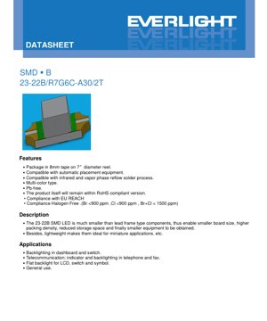
23-22B/R7G6C-A30/2T एक बहु-रंगीय सरफेस माउंट डिवाइस (एसएमडी) एलईडी है जो आधुनिक, कॉम्पैक्ट इलेक्ट्रॉनिक अनुप्रयोगों के लिए डिज़ाइन किया गया है। यह घटक एक ही पैकेज के भीतर दो अलग-अलग चिप प्रकारों को एकीकृत करता है: R7 चिप जो गहरा लाल रंग उत्सर्जित करती है और G6 चिप जो चमकीला पीला-हरा रंग उत्सर्जित करती है। इसका प्राथमिक लाभ इसके लघु आकार में निहित है, जो मुद्रित सर्किट बोर्ड (पीसीबी) पर उच्च पैकिंग घनत्व की सुविधा प्रदान करता है, जिससे समग्र उपकरण का आकार और वजन कम हो जाता है। यह इसे विशेष रूप से उन अनुप्रयोगों के लिए उपयुक्त बनाता है जहां स्थान और वजन महत्वपूर्ण बाधाएं हैं।
The LED is packaged on 8mm tape wound onto a 7-inch diameter reel, making it fully compatible with high-speed automatic pick-and-place equipment used in volume manufacturing. It is constructed using lead-free (Pb-free) materials and complies with key environmental regulations including RoHS, EU REACH, and halogen-free standards (Br <900 ppm, Cl <900 ppm, Br+Cl < 1500 ppm). The device is also qualified for standard infrared and vapor phase reflow soldering processes.
1.1 मुख्य लाभ और लक्षित बाजार
इस एसएमडी एलईडी के मुख्य लाभ इसके छोटे फॉर्म फैक्टर और दोहरी-रंग क्षमता से उत्पन्न होते हैं। पारंपरिक लीड-फ्रेम एलईडी की तुलना में काफी छोटा होने के कारण, यह डिजाइनरों को अधिक कॉम्पैक्ट उत्पाद बनाने में सक्षम बनाता है। घटकों और अंतिम असेंबल उत्पाद के लिए कम भंडारण स्थान लॉजिस्टिक और लागत लाभ प्रदान करता है। इसका हल्का स्वभाव पोर्टेबल और लघु उपकरणों के लिए आदर्श है।
लक्षित अनुप्रयोग विविध हैं, जो संकेतक और बैकलाइटिंग कार्यों पर केंद्रित हैं। प्रमुख बाजारों में ऑटोमोटिव इंटीरियर (जैसे, डैशबोर्ड और स्विच बैकलाइटिंग), दूरसंचार उपकरण (जैसे, टेलीफोन और फैक्स मशीनों में संकेतक और बैकलाइटिंग), और उपभोक्ता इलेक्ट्रॉनिक्स (जैसे, एलसीडी, स्विच और प्रतीकों के लिए फ्लैट बैकलाइटिंग) शामिल हैं। यह सामान्य-उद्देश्य संकेतक उपयोग के लिए भी उपयुक्त है जहां विश्वसनीय, बहु-रंगीय सिग्नलिंग की आवश्यकता होती है।
2. तकनीकी पैरामीटर विश्लेषण
2.1 Absolute Maximum Ratings
इन सीमाओं से परे डिवाइस संचालन से स्थायी क्षति हो सकती है। पूर्ण अधिकतम रेटिंग 25°C के परिवेश तापमान (Ta) पर निर्दिष्ट की गई हैं।
- रिवर्स वोल्टेज (VR): 5 V. रिवर्स बायस में इस वोल्टेज से अधिक होने पर एलईडी के सेमीकंडक्टर जंक्शन को क्षति पहुंच सकती है।
- फॉरवर्ड करंट (IF): R7 और G6 चिप्स दोनों के लिए 25 mA. यह अधिकतम सतत DC धारा है।
- शिखर अग्र धारा (IFP): दोनों चिप्स के लिए 60 mA, केवल स्पंदित स्थितियों में अनुमेय (कार्य चक्र 1/10 @ 1 kHz)।
- शक्ति क्षय (Pd): प्रत्येक चिप के लिए 60 mW. यह पैकेज द्वारा क्षय की जा सकने वाली अधिकतम शक्ति है।
- कार्य तापमान (Topr): -40 से +85 °C. यह उपकरण औद्योगिक तापमान सीमा के लिए रेटेड है।
- भंडारण तापमान (Tstg): -40 से +90 °C.
- इलेक्ट्रोस्टैटिक डिस्चार्ज (ESD): 2000 V (ह्यूमन बॉडी मॉडल). उचित ESD हैंडलिंग प्रक्रियाएं अनिवार्य हैं।
- सोल्डरिंग तापमान (Tsol): रीफ्लो सोल्डरिंग के लिए, 260°C का पीक तापमान अधिकतम 10 सेकंड तक अनुमत है। हैंड सोल्डरिंग के लिए, आयरन टिप का तापमान 350°C से नीचे होना चाहिए और प्रति टर्मिनल अधिकतम 3 सेकंड तक ही लगाया जाना चाहिए।
2.2 Electro-Optical Characteristics
जब तक अन्यथा न कहा गया हो, सामान्य प्रदर्शन Ta=25°C और IF=20mA पर मापा जाता है। इस पैकेज के लिए 130 डिग्री का व्यूइंग एंगल (2θ1/2) विशिष्ट है।
R7 (डार्क रेड) चिप के लिए:
- दीप्त तीव्रता (Iv): 18.0 एमसीडी (न्यूनतम) से 72.0 एमसीडी (अधिकतम) तक की सीमा में, जिसकी विशिष्ट सहनशीलता ±11% है।
- शिखर तरंगदैर्ध्य (λp): विशिष्ट रूप से 639 एनएम।
- प्रभावी तरंगदैर्ध्य (λd): विशिष्ट रूप से 631 एनएम।
- स्पेक्ट्रम बैंडविड्थ (Δλ): आमतौर पर 20 nm.
- फॉरवर्ड वोल्टेज (VF): 1.70 V (न्यूनतम) से 2.40 V (अधिकतम) के बीच होता है, जिसका सामान्य मान 2.00 V है।
G6 (ब्रिलियंट येलो ग्रीन) चिप के लिए:
- दीप्त तीव्रता (Iv): 14.5 mcd (न्यूनतम) से 45.0 mcd (अधिकतम) के बीच होता है, जिसकी सामान्य सहनशीलता ±11% है।
- शिखर तरंगदैर्ध्य (λp): आमतौर पर 575 nm.
- प्रभावी तरंगदैर्ध्य (λd): आमतौर पर 573 nm.
- स्पेक्ट्रम बैंडविड्थ (Δλ): आमतौर पर 20 nm.
- फॉरवर्ड वोल्टेज (VF): 1.70 V (न्यूनतम) से 2.40 V (अधिकतम) के बीच होता है, जिसका सामान्य मान 2.00 V है।
सामान्य पैरामीटर:
- रिवर्स करंट (IR): 5V के रिवर्स वोल्टेज लगाने पर दोनों चिप्स के लिए अधिकतम 10 µA।
3. बिनिंग प्रणाली स्पष्टीकरण
उत्पादन बैच के भीतर एकरूपता सुनिश्चित करने के लिए एलईडी की ल्यूमिनस इंटेंसिटी को बिन में वर्गीकृत किया जाता है। इससे डिजाइनर विशिष्ट चमक आवश्यकताओं को पूरा करने वाले घटकों का चयन कर सकते हैं।
3.1 R7 चिप बिनिंग
R7 डार्क रेड एलईडी को IF=20mA पर मापी गई उनकी ल्यूमिनस इंटेंसिटी के आधार पर तीन बिन में वर्गीकृत किया जाता है।
- बिन कोड 1: 18.0 एमसीडी (न्यूनतम) से 28.5 एमसीडी (अधिकतम)
- बिन कोड 2: 28.5 एमसीडी (न्यूनतम) से 45.0 एमसीडी (अधिकतम)
- बिन कोड 3: 45.0 एमसीडी (न्यूनतम) से 72.0 एमसीडी (अधिकतम)
3.2 G6 चिप बिनिंग
G6 चमकीले पीले-हरे एलईडी को भी तीन बिन में वर्गीकृत किया गया है।
- बिन कोड 1: 14.5 mcd (न्यूनतम) से 18.0 mcd (अधिकतम)
- बिन कोड 2: 18.0 एमसीडी (न्यूनतम) से 28.5 एमसीडी (अधिकतम)
- बिन कोड 3: 28.5 एमसीडी (न्यूनतम) से 45.0 एमसीडी (अधिकतम)
बिन कोड उत्पाद पैकेजिंग लेबल (\"CAT\" के अंतर्गत) पर दर्शाया गया है। डिजाइनरों को अपने अनुप्रयोग के लिए वांछित चमक स्तर की गारंटी के लिए ऑर्डर करते समय आवश्यक बिन कोड निर्दिष्ट करना चाहिए।
4. प्रदर्शन वक्र विश्लेषण
डेटाशीट में R7 और G6 दोनों चिप्स के लिए विशिष्ट विद्युत-प्रकाशीय अभिलक्षण वक्र शामिल हैं। हालांकि विशिष्ट ग्राफिकल डेटा पाठ्य रूप में प्रदान नहीं किया गया है, ये वक्र आम तौर पर अग्र धारा (IF) और दीप्त तीव्रता (Iv), अग्र वोल्टेज (VF) के बीच संबंध, और प्रकाश उत्पादन पर परिवेश के तापमान के प्रभाव को दर्शाते हैं।
विशिष्ट वक्रों से मुख्य अनुमान: दोनों एलईडी प्रकारों के लिए, दीप्त तीव्रता अग्र धारा के साथ बढ़ती है लेकिन रैखिक रूप से नहीं, विशेष रूप से जब धारा अधिकतम रेटिंग के निकट पहुंचती है। अग्र वोल्टेज का एक ऋणात्मक तापमान गुणांक होता है, जिसका अर्थ है कि यह जंक्शन तापमान बढ़ने पर थोड़ा कम हो जाता है। संचालन तापमान सीमा पर सुसंगत प्रकाशीय प्रदर्शन बनाए रखने के लिए उपयुक्त करंट-लिमिटिंग सर्किट और थर्मल प्रबंधन डिजाइन करने के लिए इन वक्रों को समझना महत्वपूर्ण है।
5. यांत्रिक और पैकेज सूचना
5.1 पैकेज आउटलाइन आयाम
23-22B SMD LED का एक विशिष्ट भौतिक फुटप्रिंट होता है। पैकेज आउटलाइन ड्राइंग PCB लैंड पैटर्न डिजाइन के लिए महत्वपूर्ण आयाम प्रदान करती है। मुख्य आयामों में समग्र लंबाई, चौड़ाई और ऊंचाई, साथ ही सोल्डर पैड का स्थान और आकार शामिल हैं। कैथोड (नकारात्मक टर्मिनल) आमतौर पर पैकेज पर एक चिह्न द्वारा पहचाना जाता है। अन्यथा निर्दिष्ट न होने पर सभी सहनशीलताएं ±0.1mm हैं। उचित सोल्डरिंग और यांत्रिक स्थिरता सुनिश्चित करने के लिए डिजाइनरों को इन आयामों का पालन करना चाहिए।
5.2 नमी प्रतिरोधी पैकेजिंग
घटकों को परिवेशीय आर्द्रता से क्षति को रोकने के लिए नमी-संवेदनशील पैकेजिंग में भेजा जाता है। पैकेज में एलईडी से भरी एक कैरियर टेप होती है, जिसे एक डिसिकेंट और एक आर्द्रता संकेतक कार्ड के साथ एक एल्यूमीनियम नमी-रोधी बैग के अंदर रखा जाता है। स्वचालित असेंबली उपकरणों के साथ संगतता सुनिश्चित करने के लिए रील के आयाम और कैरियर टेप पॉकेट के आयाम निर्दिष्ट किए गए हैं। प्रत्येक रील में 2000 टुकड़े होते हैं।
6. सोल्डरिंग और असेंबली दिशानिर्देश
6.1 भंडारण और हैंडलिंग
- उपयोग के लिए तैयार होने तक नमी-रोधी बैग न खोलें।
- खोलने से पहले: ≤ 30°C और ≤ 90% RH पर संग्रहित करें।
- खोलने के बाद: \"फ्लोर लाइफ\" ≤ 30°C और ≤ 60% RH पर 1 वर्ष है। अप्रयुक्त भागों को एक सूखे पैकेज में पुनः सील करना होगा।
- यदि डिसिकेंट नमी के संपर्क में आने का संकेत देता है या भंडारण समय सीमा समाप्त हो जाती है, तो सोल्डरिंग से पहले एक बेकिंग उपचार (60 ± 5°C, 24 घंटे के लिए) आवश्यक है।
6.2 रीफ्लो सोल्डरिंग प्रोफाइल
एक लीड-फ्री (Pb-free) रीफ्लो प्रोफाइल की सिफारिश की जाती है:
- प्री-हीटिंग: 60–120 सेकंड के लिए 150–200°C.
- 217°C (लिक्विडस) से ऊपर का समय: 60–150 सेकंड.
- पीक तापमान: अधिकतम 260°C, अधिकतम 10 सेकंड के लिए बनाए रखा जाता है.
- हीटिंग दर: 255°C से ऊपर अधिकतम 6°C/सेकंड।
- ठंडा करने की दर: अधिकतम 3°C/सेकंड।
- रीफ्लो सोल्डरिंग दो बार से अधिक नहीं की जानी चाहिए।
6.3 हैंड सोल्डरिंग और मरम्मत
- Use a soldering iron with a tip temperature < 350°C and capacity < 25W.
- प्रति टर्मिनल सोल्डरिंग समय 3 सेकंड तक सीमित करें।
- हीटिंग के दौरान एलईडी पर तनाव से बचें और सोल्डरिंग के बाद पीसीबी को वार्प न करें।
- सोल्डरिंग के बाद मरम्मत की अनुशंसा नहीं की जाती है। यदि अपरिहार्य हो, तो दोनों टर्मिनलों को एक साथ गर्म करने के लिए एक विशेष डबल-हेड सोल्डरिंग आयरन का उपयोग करें और पुष्टि करें कि एलईडी की विशेषताएं ख़राब नहीं हुई हैं।
7. पैकेजिंग और ऑर्डरिंग जानकारी
रील पर उत्पाद लेबल ट्रेसबिलिटी और सही अनुप्रयोग के लिए आवश्यक जानकारी प्रदान करता है:
- CPN: Customer's Product Number
- P/N: Product Number (e.g., 23-22B/R7G6C-A30/2T)
- QTY: Packing Quantity (2000 pcs/reel)
- CAT: Luminous Intensity Rank (Bin Code)
- HUE: Chromaticity Coordinates & Pradhan Wavelength Rank
- संदर्भ: फॉरवर्ड वोल्टेज रैंक
- LOT No: Manufacturing Lot Number
8. एप्लिकेशन डिज़ाइन विचार
8.1 सर्किट सुरक्षा
Critical: LED के साथ हमेशा एक बाहरी करंट-लिमिटिंग रेसिस्टर श्रृंखला में उपयोग किया जाना चाहिए। फॉरवर्ड वोल्टेज की एक सीमा होती है (1.7V से 2.4V), और IV विशेषता खड़ी होती है। यदि कोई रेसिस्टर मौजूद नहीं है, तो आपूर्ति वोल्टेज में एक छोटा सा परिवर्तन फॉरवर्ड करंट में एक बड़ा, संभावित रूप से विनाशकारी परिवर्तन पैदा कर सकता है। रेसिस्टर मान की गणना अधिकतम आपूर्ति वोल्टेज और LED की अधिकतम फॉरवर्ड करंट रेटिंग के आधार पर की जानी चाहिए, सबसे खराब स्थिति वाले फॉरवर्ड वोल्टेज को ध्यान में रखते हुए।
8.2 थर्मल प्रबंधन
हालांकि पावर डिसिपेशन कम है (60mW), निर्दिष्ट ऑपरेटिंग रेंज के भीतर जंक्शन तापमान बनाए रखना दीर्घकालिक विश्वसनीयता और स्थिर प्रकाश उत्पादन के लिए महत्वपूर्ण है। पर्याप्त PCB कॉपर क्षेत्र या थर्मल वाया का उपयोग सुनिश्चित करें, खासकर यदि कई LED एक साथ निकटता से रखे गए हैं या यदि परिवेश का तापमान अधिक है।
8.3 एप्लिकेशन प्रतिबंध
यह उत्पाद सामान्य वाणिज्यिक और औद्योगिक अनुप्रयोगों के लिए डिज़ाइन किया गया है। यह पूर्व परामर्श और संभावित अतिरिक्त योग्यता के बिना उच्च-विश्वसनीयता अनुप्रयोगों जैसे कि सैन्य/एयरोस्पेस, ऑटोमोटिव सुरक्षा/सुरक्षा प्रणालियों (उदाहरण के लिए, एयरबैग, ब्रेकिंग), या जीवन-महत्वपूर्ण चिकित्सा उपकरणों के लिए विशेष रूप से योग्य नहीं है।
9. तकनीकी तुलना और विभेदन
23-22B का प्राथमिक विभेदन एक ही, बहुत कॉम्पैक्ट SMD पैकेज के भीतर इसकी मल्टी-कलर क्षमता में निहित है। दो अलग-अलग सिंगल-कलर LED का उपयोग करने की तुलना में, यह PCB स्थान बचाता है और असेंबली को सरल बनाता है। दोनों रंगों के लिए AlGaInP सामग्री का उपयोग अच्छी दीप्तिमान दक्षता और रंग शुद्धता प्रदान करता है। मानक, उच्च-मात्रा SMT प्रक्रियाओं के साथ इसकी संगतता इसे बड़े पैमाने पर उत्पादित उपभोक्ता और ऑटोमोटिव इंटीरियर इलेक्ट्रॉनिक्स के लिए एक लागत-प्रभावी समाधान बनाती है।
10. अक्सर पूछे जाने वाले प्रश्न (FAQ)
10.1 क्या मैं R7 और G6 चिप्स को स्वतंत्र रूप से संचालित कर सकता हूँ?
हां, 23-22B पैकेज में दो विद्युत रूप से पृथक एलईडी चिप्स होते हैं। उनके अलग-अलग एनोड और कैथोड कनेक्शन होते हैं, जो उन्हें अलग-अलग करंट-लिमिटिंग सर्किट द्वारा स्वतंत्र रूप से ड्राइव किए जाने की अनुमति देते हैं। यह डायनेमिक कलर मिक्सिंग या स्वतंत्र सिग्नलिंग को सक्षम बनाता है।
10.2 बिनिंग प्रणाली का उद्देश्य क्या है?
बिनिंग एक उत्पादन रन के भीतर चमक की स्थिरता सुनिश्चित करती है। एक समान रूप की आवश्यकता वाले अनुप्रयोगों (जैसे, संकेतकों की एक सरणी की बैकलाइटिंग) के लिए, दृश्यमान चमक भिन्नताओं से बचने के लिए एक ही बिन कोड से एलईडी निर्दिष्ट करना और उपयोग करना आवश्यक है।
10.3 नमी-संवेदनशील पैकेजिंग क्यों आवश्यक है?
एसएमडी पैकेज हवा से नमी अवशोषित कर सकते हैं। उच्च-तापमान रीफ्लो सोल्डरिंग प्रक्रिया के दौरान, यह फंसी हुई नमी तेजी से फैल सकती है, जिससे आंतरिक परत अलग होना या "पॉपकॉर्निंग" हो सकता है, जो पैकेज को दरार देता है और डिवाइस को नष्ट कर देता है। भंडारण और परिवहन के दौरान नमी-रोधी बैग और सिलिका जेल इसे रोकते हैं।
11. डिज़ाइन और उपयोग केस स्टडी
परिदृश्य: एक नेटवर्क राउटर के लिए मल्टी-फंक्शन स्टेटस इंडिकेटर डिजाइन करना। एक डिजाइनर को पावर (स्थिर लाल), नेटवर्क गतिविधि (हरी रोशनी का टिमटिमाना), और एक फॉल्ट स्थिति (लाल/हरा बारी-बारी से) दिखाने के लिए एक ही घटक की आवश्यकता है। 23-22B एक आदर्श विकल्प है। इसका छोटा आकार सीमित फ्रंट-पैनल स्थान में फिट बैठता है। स्वतंत्र लाल (R7) और हरे (G6) चिप्स को ट्रांजिस्टर ड्राइवरों के माध्यम से एक साधारण माइक्रोकंट्रोलर जीपीआईओ पिन द्वारा नियंत्रित किया जा सकता है। दोनों रंगों के लिए बिन कोड 2 निर्दिष्ट करके, सभी निर्मित इकाइयों में एक समान चमक प्राप्त की जाती है। डिजाइनर रीफ्लो प्रोफाइल दिशानिर्देशों का पालन करता है और उत्पाद के जीवनकाल में विश्वसनीय संचालन सुनिश्चित करने के लिए उपयुक्त श्रृंखला प्रतिरोधक (उदाहरण के लिए, 5V आपूर्ति के लिए 150 ओम, सबसे खराब स्थिति Vf के लिए गणना की गई) शामिल करता है।
12. कार्य सिद्धांत
लाइट एमिटिंग डायोड (LED) अर्धचालक उपकरण हैं जो विद्युत धारा प्रवाहित होने पर प्रकाश उत्सर्जित करते हैं। इस घटना को इलेक्ट्रोलुमिनेसेंस कहा जाता है। 23-22B में, R7 चिप एक AlGaInP (एल्युमिनियम गैलियम इंडियम फॉस्फाइड) अर्धचालक संरचना का उपयोग करता है जिसे स्पेक्ट्रम के लाल भाग (लगभग 631nm प्रमुख तरंगदैर्ध्य) में प्रकाश उत्सर्जित करने के लिए अनुकूलित किया गया है। G6 चिप पीले-हरे क्षेत्र (लगभग 573nm) में प्रकाश उत्सर्जित करने के लिए AlGaInP की एक अलग संरचना का उपयोग करता है। जब चिप की बैंडगैप ऊर्जा से अधिक का एक फॉरवर्ड वोल्टेज लगाया जाता है, तो इलेक्ट्रॉन और होल अर्धचालक के सक्रिय क्षेत्र में पुनर्संयोजित होते हैं, और फोटॉन (प्रकाश) के रूप में ऊर्जा मुक्त करते हैं। विशिष्ट सामग्री संरचना उत्सर्जित प्रकाश की तरंगदैर्ध्य (रंग) निर्धारित करती है।
13. प्रौद्योगिकी रुझान
संकेतक और बैकलाइट एलईडी में रुझान उच्च दक्षता (प्रति वाट विद्युत इनपुट में अधिक प्रकाश उत्पादन), डिजाइन लचीलेपन के लिए छोटे पैकेज आकार और तापमान एवं जीवनकाल में बेहतर रंग स्थिरता और संगति की ओर बना हुआ है। 23-22B जैसे मल्टी-चिप पैकेज एकीकरण के रुझान का प्रतिनिधित्व करते हैं, जो पीसीबी पर घटकों की संख्या को कम करते हैं। इसके अलावा, पर्यावरण अनुपालन (सीसा-मुक्त, हैलोजन-मुक्त) अब वैश्विक नियमों द्वारा प्रेरित एक मानक आवश्यकता है। भविष्य के विकास में और भी पतले पैकेज और "स्मार्ट एलईडी" मॉड्यूल के लिए नियंत्रण सर्किटरी के साथ एकीकरण शामिल हो सकते हैं।
LED विनिर्देशन शब्दावली
एलईडी तकनीकी शब्दों की पूर्ण व्याख्या
प्रकाशविद्युत प्रदर्शन
| शब्द | इकाई/प्रतिनिधित्व | सरल व्याख्या | महत्वपूर्ण क्यों |
|---|---|---|---|
| Luminous Efficacy | lm/W (lumens per watt) | प्रति वाट बिजली की प्रकाश उत्पादन क्षमता, उच्च मान का अर्थ है अधिक ऊर्जा कुशल। | सीधे ऊर्जा दक्षता ग्रेड और बिजली लागत निर्धारित करता है। |
| Luminous Flux | lm (lumens) | स्रोत द्वारा उत्सर्जित कुल प्रकाश, जिसे आमतौर पर "चमक" कहा जाता है। | यह निर्धारित करता है कि प्रकाश पर्याप्त चमकीला है या नहीं। |
| Viewing Angle | ° (डिग्री), उदाहरणार्थ, 120° | वह कोण जहाँ प्रकाश की तीव्रता आधी रह जाती है, यह बीम की चौड़ाई निर्धारित करता है। | प्रकाशन सीमा और एकरूपता को प्रभावित करता है। |
| CCT (कलर टेम्परेचर) | K (केल्विन), उदाहरणार्थ, 2700K/6500K | प्रकाश की गर्माहट/ठंडक, कम मान पीलेपन/गर्माहट, अधिक मान सफेदी/ठंडक देते हैं। | प्रकाश व्यवस्था का वातावरण और उपयुक्त परिदृश्य निर्धारित करता है। |
| CRI / Ra | इकाईहीन, 0–100 | वस्तुओं के रंगों को सटीक रूप से प्रस्तुत करने की क्षमता, Ra≥80 अच्छा माना जाता है। | रंग की प्रामाणिकता को प्रभावित करता है, मॉल, संग्रहालय जैसे उच्च मांग वाले स्थानों में प्रयुक्त। |
| SDCM | MacAdam ellipse steps, jaise ki, "5-step" | Rang samanvay metrik, chhote steps ka matlab hai zyada saman rang. | LED ke ek hi batch mein ek saman rang ki suraksha karta hai. |
| Pradhan Wavelength | nm (nanometers), jaise ki, 620nm (laal) | Rangeen LED ke rang ke sambandhit wavelength. | लाल, पीले, हरे मोनोक्रोम LED के रंग का निर्धारण करता है। |
| Spectral Distribution | Wavelength vs intensity curve | तरंगदैर्ध्य के पार तीव्रता वितरण दर्शाता है। | रंग प्रतिपादन और गुणवत्ता को प्रभावित करता है। |
विद्युत मापदंड
| शब्द | प्रतीक | सरल व्याख्या | डिज़ाइन संबंधी विचार |
|---|---|---|---|
| अग्र वोल्टेज | Vf | एलईडी चालू करने के लिए न्यूनतम वोल्टेज, जैसे "प्रारंभिक सीमा"। | ड्राइवर वोल्टेज ≥Vf होना चाहिए, श्रृंखला में जुड़े एलईडी के लिए वोल्टेज जुड़ते हैं। |
| फॉरवर्ड करंट | If | सामान्य LED संचालन के लिए करंट मान। | Usually constant current drive, current determines brightness & lifespan. |
| मैक्स पल्स करंट | Ifp | छोटी अवधि के लिए सहनीय शिखर धारा, डिमिंग या फ्लैशिंग के लिए उपयोग की जाती है। | Pulse width & duty cycle must be strictly controlled to avoid damage. |
| रिवर्स वोल्टेज | Vr | अधिकतम रिवर्स वोल्टेज जिसे LED सहन कर सकता है, इससे अधिक होने पर ब्रेकडाउन हो सकता है। | सर्किट को रिवर्स कनेक्शन या वोल्टेज स्पाइक्स को रोकना चाहिए। |
| थर्मल रेजिस्टेंस | Rth (°C/W) | चिप से सोल्डर तक ऊष्मा स्थानांतरण के लिए प्रतिरोध, कम होना बेहतर है। | उच्च थर्मल रेजिस्टेंस के लिए मजबूत हीट डिसिपेशन की आवश्यकता होती है। |
| ESD इम्यूनिटी | V (HBM), e.g., 1000V | स्थिर विद्युत निर्वहन को सहन करने की क्षमता, उच्च मान का अर्थ है कम संवेदनशील। | उत्पादन में एंटी-स्टैटिक उपायों की आवश्यकता, विशेष रूप से संवेदनशील एलईडी के लिए। |
Thermal Management & Reliability
| शब्द | प्रमुख मापदंड | सरल व्याख्या | प्रभाव |
|---|---|---|---|
| जंक्शन तापमान | Tj (°C) | एलईडी चिप के अंदर का वास्तविक कार्य तापमान। | हर 10°C कमी जीवनकाल को दोगुना कर सकती है; बहुत अधिक तापमान प्रकाश क्षय, रंग परिवर्तन का कारण बनता है। |
| Lumen Depreciation | L70 / L80 (hours) | चमक के प्रारंभिक मान के 70% या 80% तक गिरने में लगने वाला समय। | सीधे एलईडी "सेवा जीवन" को परिभाषित करता है। |
| लुमेन रखरखाव | % (उदाहरण के लिए, 70%) | समय के बाद बची हुई चमक का प्रतिशत। | दीर्घकालिक उपयोग में चमक की धारण क्षमता को दर्शाता है। |
| कलर शिफ्ट | Δu′v′ या मैकएडम दीर्घवृत्त | उपयोग के दौरान रंग परिवर्तन की डिग्री। | प्रकाश व्यवस्था के दृश्यों में रंग स्थिरता को प्रभावित करता है। |
| Thermal Aging | सामग्री का क्षरण | दीर्घकालिक उच्च तापमान के कारण ह्रास। | चमक में कमी, रंग परिवर्तन, या ओपन-सर्किट विफलता का कारण बन सकता है। |
Packaging & Materials
| शब्द | सामान्य प्रकार | सरल व्याख्या | Features & Applications |
|---|---|---|---|
| पैकेज प्रकार | EMC, PPA, Ceramic | हाउसिंग सामग्री चिप की सुरक्षा करती है, ऑप्टिकल/थर्मल इंटरफेस प्रदान करती है। | EMC: अच्छी हीट रेजिस्टेंस, कम लागत; सिरेमिक: बेहतर हीट डिसिपेशन, लंबी लाइफ। |
| चिप संरचना | फ्रंट, फ्लिप चिप | चिप इलेक्ट्रोड व्यवस्था। | फ्लिप चिप: बेहतर हीट डिसिपेशन, उच्च एफिकेसी, हाई-पावर के लिए। |
| फॉस्फर कोटिंग | YAG, सिलिकेट, नाइट्राइड | नीले चिप को ढकता है, कुछ को पीले/लाल रंग में परिवर्तित करता है, सफेद रंग में मिश्रित करता है। | विभिन्न फॉस्फर दक्षता, CCT, और CRI को प्रभावित करते हैं। |
| लेंस/ऑप्टिक्स | फ्लैट, माइक्रोलेंस, TIR | प्रकाश वितरण को नियंत्रित करने वाली सतह पर प्रकाशीय संरचना। | दृश्य कोण और प्रकाश वितरण वक्र निर्धारित करता है। |
Quality Control & Binning
| शब्द | बिनिंग सामग्री | सरल व्याख्या | उद्देश्य |
|---|---|---|---|
| Luminous Flux Bin | कोड उदाहरणार्थ, 2G, 2H | चमक के आधार पर समूहीकृत, प्रत्येक समूह के न्यूनतम/अधिकतम ल्यूमेन मान होते हैं। | एक ही बैच में समान चमक सुनिश्चित करता है। |
| वोल्टेज बिन | कोड उदाहरणार्थ, 6W, 6X | फॉरवर्ड वोल्टेज रेंज के आधार पर समूहीकृत। | ड्राइवर मिलान में सहायता करता है, सिस्टम दक्षता में सुधार करता है। |
| Color Bin | 5-step MacAdam ellipse | रंग निर्देशांक के अनुसार समूहीकृत, एक सख्त सीमा सुनिश्चित करता है। | रंग स्थिरता की गारंटी देता है, फिक्स्चर के भीतर असमान रंग से बचाता है। |
| CCT Bin | 2700K, 3000K आदि। | CCT के अनुसार समूहीकृत, प्रत्येक की अपनी संबंधित निर्देशांक सीमा है। | विभिन्न दृश्य CCT आवश्यकताओं को पूरा करता है। |
Testing & Certification
| शब्द | मानक/परीक्षण | सरल व्याख्या | महत्व |
|---|---|---|---|
| LM-80 | ल्यूमेन रखरखाव परीक्षण | निरंतर तापमान पर दीर्घकालिक प्रकाश व्यवस्था, चमक क्षय का रिकॉर्डिंग। | LED जीवन का अनुमान लगाने के लिए उपयोग किया जाता है (TM-21 के साथ)। |
| TM-21 | जीवन अनुमान मानक | LM-80 डेटा के आधार पर वास्तविक परिस्थितियों में जीवन का अनुमान लगाता है। | वैज्ञानिक जीवन पूर्वानुमान प्रदान करता है। |
| IESNA | Illuminating Engineering Society | प्रकाशिक, विद्युत, तापीय परीक्षण विधियों को शामिल करता है। | उद्योग-मान्यता प्राप्त परीक्षण आधार। |
| RoHS / REACH | पर्यावरण प्रमाणन | हानिकारक पदार्थों (सीसा, पारा) की अनुपस्थिति सुनिश्चित करता है। | अंतरराष्ट्रीय स्तर पर बाजार पहुंच की आवश्यकता। |
| ENERGY STAR / DLC | ऊर्जा दक्षता प्रमाणन | प्रकाश व्यवस्था के लिए ऊर्जा दक्षता और प्रदर्शन प्रमाणन। | सरकारी खरीद, सब्सिडी कार्यक्रमों में उपयोग, प्रतिस्पर्धात्मकता बढ़ाता है। |