विषय सूची
- 1. उत्पाद अवलोकन
- 2. तकनीकी पैरामीटर गहन विश्लेषण
- 2.1 पूर्ण अधिकतम रेटिंग्स
- 2.2 इलेक्ट्रो-ऑप्टिकल विशेषताएँ
- 3. बिनिंग सिस्टम व्याख्या
- 3.1 Luminous Intensity Binning
- 3.2 Dominant Wavelength Binning
- 3.3 अग्र वोल्टेज बिनिंग
- 4. प्रदर्शन वक्र विश्लेषण
- 4.1 Forward Current vs. Forward Voltage (I-V Curve)
- 4.2 Relative Luminous Intensity vs. Ambient Temperature
- 4.3 Relative Luminous Intensity vs. Forward Current
- 4.4 स्पेक्ट्रम वितरण
- 4.5 अग्र धारा डीरेटिंग वक्र
- 4.6 Radiation Diagram
- 5. Mechanical and Packaging Information
- 5.1 Package Dimensions
- 5.2 नमी प्रतिरोधी पैकेजिंग और रील जानकारी
- 6. सोल्डरिंग और असेंबली दिशानिर्देश
- 6.1 Storage and Handling
- 6.2 रीफ्लो सोल्डरिंग प्रोफाइल (Pb-free)
- 6.3 हैंड सोल्डरिंग
- 7. एप्लिकेशन सुझाव
- 7.1 विशिष्ट एप्लिकेशन परिदृश्य
- 7.2 डिज़ाइन संबंधी विचार और सावधानियाँ
- 8. तकनीकी तुलना और विभेदन
- 9. अक्सर पूछे जाने वाले प्रश्न (तकनीकी मापदंडों के आधार पर)
- 9.1 करंट-लिमिटिंग रेसिस्टर पूरी तरह से आवश्यक क्यों है?
- 9.2 क्या मैं इस LED को 3.3V या 5V सप्लाई से चला सकता हूँ?
- 9.3 यदि मैं LED को लगातार उसकी चरम धारा (60mA) पर चलाऊं तो क्या होगा?
- 9.4 मैं रील लेबल पर बिन कोड्स की व्याख्या कैसे करूं?
- 9.5 भंडारण और बेकिंग प्रक्रिया इतनी महत्वपूर्ण क्यों है?
- 10. व्यावहारिक डिज़ाइन और उपयोग केस
- 10.1 एक मल्टी-एलईडी स्टेटस इंडिकेटर पैनल डिज़ाइन करना
- 11. कार्य सिद्धांत परिचय
- 12. Technology Trends and Context
1. उत्पाद अवलोकन
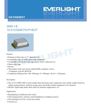
19-213/G6W-FN1P1B/3T एक सरफेस-माउंट डिवाइस (एसएमडी) एलईडी है जो उच्च-घनत्व इलेक्ट्रॉनिक असेंबली के लिए डिज़ाइन किया गया है। इसमें एक कॉम्पैक्ट फॉर्म फैक्टर है जो छोटे प्रिंटेड सर्किट बोर्ड (पीसीबी) डिज़ाइन, कम भंडारण आवश्यकताओं को सक्षम बनाता है, और अंततः अंतिम उपकरणों के लघुरूपण में योगदान देता है। इसके हल्के निर्माण के कारण यह उन अनुप्रयोगों के लिए विशेष रूप से उपयुक्त है जहां स्थान और वजन महत्वपूर्ण बाधाएं हैं।
यह एलईडी एक मोनो-कलर प्रकार का है, जो एक ब्रिलियंट येलो ग्रीन प्रकाश उत्सर्जित करता है। यह AlGaInP (एल्युमिनियम गैलियम इंडियम फॉस्फाइड) अर्धचालक सामग्री का उपयोग करके निर्मित है, जो पीले से लाल तरंगदैर्ध्य स्पेक्ट्रम में अपनी उच्च दक्षता के लिए जानी जाती है। डिवाइस एक वाटर-डिफ्यूज़्ड रेजिन पैकेज में रखा गया है, जो एक विस्तृत व्यूइंग एंगल प्राप्त करने में मदद करता है।
The product is compliant with key environmental and safety standards, including being Pb-free (lead-free), RoHS compliant, EU REACH compliant, and Halogen Free, with bromine (Br) and chlorine (Cl) content strictly controlled below specified limits (Br <900 ppm, Cl <900 ppm, Br+Cl < 1500 ppm).
2. तकनीकी पैरामीटर गहन विश्लेषण
2.1 पूर्ण अधिकतम रेटिंग्स
पूर्ण अधिकतम रेटिंग्स उन सीमाओं को परिभाषित करती हैं जिनके परे डिवाइस को स्थायी क्षति हो सकती है। ये रेटिंग्स 25°C के परिवेश तापमान (Ta) पर निर्दिष्ट हैं और किसी भी संचालन स्थिति में इन्हें पार नहीं किया जाना चाहिए।
- Reverse Voltage (VR): 5 V. रिवर्स दिशा में इससे अधिक वोल्टेज लगाने से जंक्शन ब्रेकडाउन हो सकता है।
- Continuous Forward Current (IF): 25 mA. यह अधिकतम DC धारा है जो LED के माध्यम से लगातार प्रवाहित की जा सकती है।
- Peak Forward Current (IFP): 60 mA. यह रेटिंग 1 kHz पर 1/10 ड्यूटी साइकिल के साथ पल्स्ड स्थितियों में लागू होती है। यह कम अवधि के लिए उच्च तात्कालिक धाराओं की अनुमति देती है, जैसे कि मल्टीप्लेक्सिंग सर्किट में।
- पावर डिसिपेशन (Pd): 60 mW. यह डिवाइस द्वारा ऊष्मा के रूप में व्यय की जा सकने वाली अधिकतम शक्ति की मात्रा है। इस सीमा से अधिक होने पर अत्यधिक गर्मी और जीवनकाल में कमी आ सकती है।
- ऑपरेटिंग तापमान (Topr): -40°C से +85°C. LED को इस परिवेशी तापमान सीमा के भीतर कार्य करने के लिए डिज़ाइन किया गया है।
- भंडारण तापमान (Tstg): -40°C से +90°C. डिवाइस को संचालन में न होने पर इस सीमा के भीतर संग्रहीत किया जा सकता है।
- इलेक्ट्रोस्टैटिक डिस्चार्ज (ईएसडी) ह्यूमन बॉडी मॉडल (एचबीएम): 2000 V. यह एलईडी की स्टैटिक बिजली के प्रति संवेदनशीलता को दर्शाता है। असेंबली और हैंडलिंग के दौरान उचित ईएसडी हैंडलिंग प्रक्रियाओं का पालन किया जाना चाहिए।
- सोल्डरिंग तापमान (Tsol): यह उपकरण 260°C पर अधिकतम 10 सेकंड के लिए रीफ्लो सोल्डरिंग या प्रति टर्मिनल 350°C पर अधिकतम 3 सेकंड के लिए हैंड सोल्डरिंग को सहन कर सकता है।
2.2 इलेक्ट्रो-ऑप्टिकल विशेषताएँ
Electro-Optical Characteristics को Ta=25°C और IF=20 mA पर मापा जाता है, जो एक विशिष्ट परीक्षण स्थिति है। ये पैरामीटर LED के प्रकाश उत्पादन और विद्युतीय व्यवहार को परिभाषित करते हैं।
- प्रदीप्त तीव्रता (Iv): यह न्यूनतम 28.5 mcd से लेकर अधिकतम 57.0 mcd तक होती है। वास्तविक मान बिनिंग प्रक्रिया द्वारा निर्धारित किया जाता है (धारा 3 देखें)। प्रदीप्त तीव्रता पर ±11% सहनशीलता लागू होती है।
- दर्शन कोण (2θ1/2): आमतौर पर 130 डिग्री। यह वह पूर्ण कोण है जिस पर दीप्त तीव्रता, 0 डिग्री (अक्ष पर) की तीव्रता की आधी होती है। चौड़ा दृश्य कोण जल-विसरित रेजिन का परिणाम है, जो इसे व्यापक प्रकाशन की आवश्यकता वाले अनुप्रयोगों के लिए उपयुक्त बनाता है।
- शिखर तरंगदैर्घ्य (λp): आमतौर पर 575 nm। यह वह तरंगदैर्घ्य है जिस पर उत्सर्जित प्रकाश का स्पेक्ट्रमी शक्ति वितरण अपने अधिकतम पर होता है।
- प्रमुख तरंगदैर्घ्य (λd): 570.0 nm से 574.5 nm तक की सीमा में होता है। यह वह एकल तरंगदैर्ध्य है जिसे मानव आंख उत्सर्जित प्रकाश के रंग से सबसे अच्छा मेल खाता हुआ अनुभव करती है। इसकी सहनशीलता ±1 nm है।
- स्पेक्ट्रम विकिरण बैंडविड्थ (Δλ): आमतौर पर 20 nm होता है। यह पैरामीटर उत्सर्जित प्रकाश की वर्णक्रमीय चौड़ाई को दर्शाता है, जिसे अधिकतम तीव्रता के आधे पर मापा जाता है (फुल विड्थ ऐट हाफ मैक्सिमम - FWHM)।
- फॉरवर्ड वोल्टेज (VF): IF=20mA पर 1.75 V से 2.35 V तक की सीमा में होता है। विशिष्ट मान वोल्टेज बिन द्वारा निर्धारित होता है (धारा 3 देखें)। ±0.1V का सहनशीलता मान लागू होता है।
- रिवर्स करंट (IR): जब 5V का रिवर्स वोल्टेज (VR) लगाया जाता है तो अधिकतम 10 μA होता है। यह ध्यान रखना महत्वपूर्ण है कि यह डिवाइस रिवर्स ऑपरेशन के लिए डिज़ाइन नहीं किया गया है; यह टेस्ट कंडीशन केवल विशेषता निर्धारण के लिए है।
3. बिनिंग सिस्टम व्याख्या
रंग और चमक में एकरूपता सुनिश्चित करने के लिए, एलईडी को प्रमुख पैरामीटर्स के आधार पर बिन में वर्गीकृत किया जाता है। यह डिज़ाइनरों को ऐसे पार्ट्स का चयन करने की अनुमति देता है जो एकरूपता के लिए विशिष्ट एप्लिकेशन आवश्यकताओं को पूरा करते हैं।
3.1 Luminous Intensity Binning
एलईडी को IF=20mA पर उनकी मापी गई दीप्त तीव्रता के आधार पर तीन बिन (N1, N2, P1) में वर्गीकृत किया गया है।
- बिन N1: 28.5 mcd (Min) से 36.0 mcd (Max)
- Bin N2: 36.0 mcd (Min) से 45.0 mcd (Max)
- Bin P1: 45.0 mcd (Min) to 57.0 mcd (Max)
एक सख्त बिन (जैसे, केवल P1) का चयन करने से सुनिश्चित होता है कि एक सरणी में सभी एलईडी की चमक बहुत समान होगी।
3.2 Dominant Wavelength Binning
एलईडी को पीले-हरे प्रकाश के सटीक रंग को नियंत्रित करने के लिए तीन बिन (CC2, CC3, CC4) में वर्गीकृत किया जाता है।
- बिन CC2: 570.0 nm (Min) से 571.5 nm (Max)
- Bin CC3: 571.5 nm (Min) से 573.0 nm (Max)
- Bin CC4: 573.0 nm (Min) to 574.5 nm (Max)
यह बिनिंग उन अनुप्रयोगों के लिए महत्वपूर्ण है जहाँ रंग की एकरूपता सर्वोपरि है, जैसे कि मल्टी-एलईडी संकेतक या बैकलाइटिंग इकाइयों में।
3.3 अग्र वोल्टेज बिनिंग
LEDs को तीन वोल्टेज बिन (0, 1, 2) में वर्गीकृत किया जाता है ताकि श्रृंखला/समानांतर सर्किट में बिजली आपूर्ति डिजाइन और करंट मिलान का प्रबंधन किया जा सके।
- Bin 0: 1.75 V (Min) से 1.95 V (Max)
- Bin 1: 1.95 V (Min) से 2.15 V (Max)
- Bin 2: 2.15 V (Min) to 2.35 V (Max)
Using LEDs from the same voltage bin simplifies current-limiting resistor calculation and improves uniformity in driven current.
4. प्रदर्शन वक्र विश्लेषण
The datasheet provides several characteristic curves that illustrate the LED's behavior under varying conditions. Understanding these is key to robust circuit design.
4.1 Forward Current vs. Forward Voltage (I-V Curve)
I-V वक्र धारा और वोल्टेज के बीच घातांकीय संबंध दर्शाता है। इस LED के लिए, 20 mA की एक सामान्य कार्यशील धारा पर, फॉरवर्ड वोल्टेज बिन के आधार पर 1.75V और 2.35V के बीच होता है। यह वक्र एक स्थिर वोल्टेज स्रोत के बजाय एक करंट-लिमिटिंग डिवाइस (रोकनेवाला या स्थिर धारा ड्राइवर) के उपयोग के महत्व को उजागर करता है, क्योंकि वोल्टेज में थोड़ी सी वृद्धि धारा में बड़ी, संभावित रूप से हानिकारक वृद्धि का कारण बन सकती है।
4.2 Relative Luminous Intensity vs. Ambient Temperature
यह वक्र प्रकाश उत्पादन की तापमान निर्भरता को प्रदर्शित करता है। प्रकाशीय तीव्रता आमतौर पर परिवेश के तापमान में वृद्धि के साथ घटती है। उदाहरण के लिए, +85°C के अधिकतम कार्यशील तापमान पर, प्रकाश उत्पादन 25°C की तुलना में काफी कम हो सकता है। डिजाइनरों को उच्च परिवेश तापमान पर काम करने वाले अनुप्रयोगों में इस डीरेटिंग को ध्यान में रखना चाहिए ताकि यह सुनिश्चित किया जा सके कि पर्याप्त चमक बनी रहे।
4.3 Relative Luminous Intensity vs. Forward Current
यह ग्राफ दर्शाता है कि प्रकाश उत्पादन फॉरवर्ड करंट के साथ बढ़ता है, लेकिन यह संबंध पूरी तरह से रैखिक नहीं है, विशेष रूप से उच्च धाराओं पर। अनुशंसित निरंतर धारा (25 mA) से ऊपर कार्य करने से चमक में घटती प्रतिफल मिल सकती है, जबकि ऊष्मा उत्पादन में उल्लेखनीय वृद्धि होती है और लुमेन मूल्यह्रास तेज हो जाता है।
4.4 स्पेक्ट्रम वितरण
स्पेक्ट्रम वितरण वक्र एलईडी की एकवर्णी प्रकृति की पुष्टि करता है, जिसमें लगभग 575 nm (पीला-हरा) पर एक एकल शिखर और 20 nm का एक विशिष्ट FWHM है। संकीर्ण बैंडविड्थ AlGaInP-आधारित एलईडी की विशेषता है।
4.5 अग्र धारा डीरेटिंग वक्र
यह महत्वपूर्ण वक्र परिवेशी तापमान के एक फलन के रूप में अधिकतम अनुमेय अग्र धारा निर्धारित करता है। तापमान बढ़ने पर, डिवाइस की शक्ति क्षय और तापीय सीमाओं के भीतर रहने के लिए अधिकतम अनुमेय धारा को कम किया जाना चाहिए। विश्वसनीय दीर्घकालिक संचालन के लिए, डीरेटिंग वक्र का कड़ाई से पालन किया जाना चाहिए।
4.6 Radiation Diagram
एक विसरित पैकेज के लिए विकिरण पैटर्न (या स्थानिक वितरण) आमतौर पर लैम्बर्टियन या निकट-लैम्बर्टियन होता है, जो 130-डिग्री के व्यापक दृश्य कोण की पुष्टि करता है। यह पैटर्न उन अनुप्रयोगों के लिए आदर्श है जिनमें केंद्रित बीम के बजाय समान, विस्तृत-क्षेत्र प्रकाश व्यवस्था की आवश्यकता होती है।
5. Mechanical and Packaging Information
5.1 Package Dimensions
एलईडी का कॉम्पैक्ट एसएमडी फुटप्रिंट है। प्रमुख आयाम (मिमी में, सहनशीलता ±0.1 मिमी जब तक निर्दिष्ट न हो) शामिल हैं:
- कुल लंबाई: 2.0 मिमी
- कुल चौड़ाई: 1.25 मिमी
- कुल ऊंचाई: 1.1 मिमी
- PCB लैंड पैटर्न डिज़ाइन के लिए लीड (टर्मिनल) आयाम और अंतराल प्रदान किए गए हैं।
कैथोड को आमतौर पर पैकेज पर एक चिह्न या एक विशिष्ट पैड ज्यामिति (जैसे, एक खांचा या हरा चिह्न) द्वारा पहचाना जाता है। डिज़ाइनरों को ध्रुवता की सही पहचान करने और सोल्डर पैड लेआउट डिज़ाइन करने के लिए विस्तृत आयाम चित्र का परामर्श लेना चाहिए।
5.2 नमी प्रतिरोधी पैकेजिंग और रील जानकारी
एलईडी को परिवेशी आर्द्रता से होने वाले नुकसान को रोकने के लिए नमी प्रतिरोधी पैकेजिंग में आपूर्ति की जाती है, जो एमएसएल (नमी संवेदनशीलता स्तर) अनुपालन के लिए महत्वपूर्ण है।
- पैकिंग: उपकरण 8 मिमी चौड़ी वाहक टेप पर पैक किए जाते हैं, और 7 इंच व्यास के रील पर लपेटे जाते हैं।
- मात्रा: प्रति रील 3000 टुकड़े।
- नमी अवरोध बैग: रील को एक एल्यूमीनियम नमी-रोधी बैग के अंदर एक सुखाने वाले पदार्थ और एक आर्द्रता संकेतक कार्ड के साथ सील किया गया है।
- लेबल सूचना: रील लेबल में महत्वपूर्ण जानकारी शामिल है जैसे कि पार्ट नंबर (P/N), मात्रा (QTY), और ल्यूमिनस इंटेंसिटी (CAT), डॉमिनेंट वेवलेंथ (HUE), और फॉरवर्ड वोल्टेज (REF) के लिए विशिष्ट बिनिंग कोड।
6. सोल्डरिंग और असेंबली दिशानिर्देश
विश्वसनीयता के लिए उचित हैंडलिंग और सोल्डरिंग आवश्यक है।
6.1 Storage and Handling
- उपयोग के लिए तैयार होने तक नमी-रोधी बैग न खोलें।
- खोलने के बाद, अनुपयोगी LEDs को ≤30°C और ≤60% सापेक्ष आर्द्रता पर संग्रहित किया जाना चाहिए।
- बैग खोलने के बाद "फ्लोर लाइफ" 168 घंटे (7 दिन) है। यदि इससे अधिक हो जाता है, या यदि डिसिकेंट इंडिकेटर संतृप्ति दिखाता है, तो उपयोग से पहले एलईडी को 60 ±5°C पर 24 घंटे के लिए बेक किया जाना चाहिए।
- हैंडलिंग के दौरान हमेशा ESD (इलेक्ट्रोस्टैटिक डिस्चार्ज) सावधानियों का पालन करें।
6.2 रीफ्लो सोल्डरिंग प्रोफाइल (Pb-free)
अनुशंसित रीफ्लो प्रोफाइल लेड-मुक्त (SAC) सोल्डर मिश्र धातुओं के लिए महत्वपूर्ण है।
- प्री-हीटिंग: 150-200°C for 60-120 seconds.
- Time Above Liquidus (TAL): 60-150 seconds above 217°C.
- Peak Temperature: अधिकतम 260°C, अधिकतम 10 सेकंड के लिए बनाए रखा जाता है।
- रैंप दरें: शिखर तक अधिकतम 6°C/सेकंड की तापन दर; अधिकतम 3°C/सेकंड की शीतलन दर।
- महत्वपूर्ण: एक ही डिवाइस पर रीफ्लो सोल्डरिंग दो बार से अधिक नहीं की जानी चाहिए।
6.3 हैंड सोल्डरिंग
यदि मैन्युअल मरम्मत आवश्यक है, तो अत्यधिक सावधानी की आवश्यकता है:
- ≤350°C टिप तापमान वाले सोल्डरिंग आयरन का उपयोग करें।
- प्रत्येक टर्मिनल पर ≤3 सेकंड के लिए गर्मी लगाएं।
- कम पावर वाले आयरन (≤25W) का उपयोग करें।
- थर्मल शॉक से बचने के लिए प्रत्येक टर्मिनल को सोल्डर करने के बीच कम से कम 2 सेकंड का अंतराल दें।
- हटाने के लिए, दोनों टर्मिनलों को एक साथ गर्म करने और एलईडी पर यांत्रिक तनाव से बचने के लिए दो-नोक वाले सोल्डरिंग आयरन की सिफारिश की जाती है।
7. एप्लिकेशन सुझाव
7.1 विशिष्ट एप्लिकेशन परिदृश्य
- Backlighting: Ideal for backlighting switches, symbols, and small dashboard indicators in automotive and consumer electronics.
- Status Indicators: दूरसंचार उपकरणों (फोन, फैक्स), नेटवर्किंग हार्डवेयर और औद्योगिक नियंत्रण पैनलों में शक्ति, कनेक्टिविटी या स्थिति संकेतकों के लिए आदर्श।
- सामान्य प्रकाश: विभिन्न प्रकार के इलेक्ट्रॉनिक उपकरणों में निम्न-स्तरीय सामान्य संकेतक उद्देश्यों के लिए उपयुक्त।
- LCD फ्लैट बैकलाइटिंग: छोटे मोनोक्रोम LCD डिस्प्ले के लिए एज-लाइटिंग प्रदान करने हेतु एरे में उपयोग किया जा सकता है।
7.2 डिज़ाइन संबंधी विचार और सावधानियाँ
- Current Limiting is Mandatory: LED के साथ हमेशा एक बाहरी करंट-लिमिटिंग रेसिस्टर या कॉन्स्टेंट-करंट ड्राइवर को सीरीज़ में इस्तेमाल करना चाहिए। एक्सपोनेंशियल I-V करैक्टरिस्टिक का मतलब है कि वोल्टेज में थोड़ा बदलाव करंट में बड़ा बदलाव लाता है, जो LED को तुरंत नष्ट कर सकता है।
- Thermal Management: हालांकि पैकेज छोटा है, बिजली का अपव्यय (60mW तक) गर्मी उत्पन्न करता है। पर्याप्त PCB कॉपर क्षेत्र या थर्मल वाया का उपयोग सुनिश्चित करें, खासकर जब उच्च परिवेशी तापमान पर या अधिकतम धारा के निकट संचालित किया जा रहा हो।
- ऑप्टिकल डिज़ाइन: 130-डिग्री का चौड़ा व्यूइंग एंगल व्यापक उत्सर्जन प्रदान करता है। अधिक निर्देशित प्रकाश के लिए, बाहरी लेंस या लाइट गाइड आवश्यक हो सकते हैं।
- स्थिरता के लिए बिनिंग: बहु-एलईडी अनुप्रयोगों (सरणियों, बैकलाइट्स) के लिए, समान रंग और चमक प्राप्त करने के लिए प्रमुख तरंगदैर्ध्य (HUE) और दीप्त तीव्रता (CAT) के लिए सख्त बिन निर्दिष्ट करें।
- यांत्रिक तनाव से बचें: सोल्डर किए गए एलईडी के आसपास पीसीबी को मोड़ें या उस पर बल न लगाएं, क्योंकि इससे सेमीकंडक्टर डाई या पैकेज के अंदर के वायर बॉन्ड्स में दरार पड़ सकती है।
8. तकनीकी तुलना और विभेदन
The 19-213 LED offers several key advantages in its category:
- Size Advantage: इसका 2.0 x 1.25 mm फुटप्रिंट पारंपरिक लीड वाले एलईडी (जैसे 3mm या 5mm गोल) से काफी छोटा है, जो पीसीबी पर उच्च घटक घनत्व को सक्षम बनाता है।
- विस्तृत दृश्य कोण: वाटर-डिफ्यूज्ड पैकेज से 130-डिग्री का कोण कई क्लियर-लेंस एसएमडी एलईडी से बेहतर है, जो द्वितीयक ऑप्टिक्स के बिना व्यापक क्षेत्र पर अधिक समान प्रकाश प्रदान करता है।
- पर्यावरण अनुपालन: RoHS, REACH और Halogen-Free मानकों के साथ पूर्ण अनुपालन इसे नवीनतम वैश्विक पर्यावरणीय नियमों और ऑटोमोटिव इंटीरियर जैसे संवेदनशील अनुप्रयोगों के लिए उपयुक्त बनाता है।
- मजबूत बिनिंग: एक सुस्पष्ट 3x3x3 बिनिंग मैट्रिक्स (तीव्रता, तरंगदैर्ध्य, वोल्टेज) डिजाइनरों को उनके अंतिम उत्पाद के प्रकाशीय और विद्युतीय प्रदर्शन पर सटीक नियंत्रण देता है, जिससे उपज और स्थिरता में सुधार होता है।
- अनुकूलता: यह मानक 8mm टेप पर पैक किया गया है और स्वचालित पिक-एंड-प्लेस मशीनों के साथ संगत है, जो इसे बड़े पैमाने की स्वचालित असेंबली लाइनों में निर्बाध रूप से फिट होने देता है।
9. अक्सर पूछे जाने वाले प्रश्न (तकनीकी मापदंडों के आधार पर)
9.1 करंट-लिमिटिंग रेसिस्टर पूरी तरह से आवश्यक क्यों है?
एलईडी का फॉरवर्ड वोल्टेज एक रेंज (1.75V-2.35V) में होता है और इसका नेगेटिव टेम्परेचर कोएफिशिएंट होता है (VF तापमान बढ़ने के साथ घटता है)। यदि इसे सीधे एक वोल्टेज स्रोत से जोड़ा जाता है, जो इसके VF से थोड़ा भी अधिक है, तो करंट अनियंत्रित रूप से बढ़ेगा, जो केवल सर्किट के पैरासिटिक रेसिस्टेंस द्वारा सीमित होगा, और लगभग निश्चित रूप से 25mA के एब्सोल्यूट मैक्सिमम रेटिंग से अधिक हो जाएगा, जिससे तत्काल विफलता होगी। रेसिस्टर एक पूर्वानुमेय और सुरक्षित ऑपरेटिंग करंट निर्धारित करता है।
9.2 क्या मैं इस LED को 3.3V या 5V सप्लाई से चला सकता हूँ?
हाँ, लेकिन आपको एक श्रृंखला रोकनेवाला (resistor) का उपयोग करना होगा। उदाहरण के लिए, 3.3V आपूर्ति और 20mA के लक्ष्य धारा के साथ, 2.1V के एक सामान्य VF को मानते हुए: R = (Vsupply - VF) / IF = (3.3V - 2.1V) / 0.020A = 60 Ohms। आप निकटतम मानक मान (जैसे, 62 Ohms) का चयन करेंगे और रोकनेवाले में वास्तविक धारा और शक्ति क्षय की गणना करेंगे। एक रूढ़िवादी डिजाइन के लिए यह सुनिश्चित करने के लिए कि धारा बहुत कम न हो जाए, हमेशा बिन से अधिकतम VF का उपयोग करें, या यह सुनिश्चित करने के लिए कि यह बहुत अधिक न हो जाए, न्यूनतम VF का उपयोग करें।
9.3 यदि मैं LED को लगातार उसकी चरम धारा (60mA) पर चलाऊं तो क्या होगा?
निरंतर स्पंदित चरम धारा रेटिंग पर संचालन पूर्ण अधिकतम रेटिंग्स का उल्लंघन है। इससे गंभीर अतितापन होगा, ल्यूमेन ह्रास नाटकीय रूप से तेज हो जाएगा (एलईडी जल्दी मंद हो जाएगी), और लगभग निश्चित रूप से कम समय में विनाशकारी विफलता होगी। 60mA रेटिंग केवल बहुत छोटे स्पंदों के लिए है।
9.4 मैं रील लेबल पर बिन कोड्स की व्याख्या कैसे करूं?
लेबल में CAT:N2, HUE:CC3, REF:1 जैसे कोड होते हैं। यह बताता है कि उस रील पर सभी एलईडी की चमकदार तीव्रता 36.0 से 45.0 mcd (N2) के बीच, प्रमुख तरंगदैर्ध्य 571.5 से 573.0 nm (CC3) के बीच और अग्र वोल्टेज 1.95 से 2.15V (1) के बीच होती है। आप ऑर्डर करते समय इन सटीक बिन को निर्दिष्ट कर सकते हैं ताकि आपके एप्लिकेशन के लिए प्रदर्शन स्थिरता की गारंटी हो सके।
9.5 भंडारण और बेकिंग प्रक्रिया इतनी महत्वपूर्ण क्यों है?
SMD पैकेज हवा से नमी अवशोषित कर सकते हैं। उच्च-तापमान रीफ्लो सोल्डरिंग प्रक्रिया के दौरान, यह फंसी हुई नमी तेजी से भाप में बदल जाती है, जिससे अत्यधिक आंतरिक दबाव पैदा होता है। इससे "पॉपकॉर्निंग" हो सकती है - एपॉक्सी रेजिन का लीड फ्रेम से विलगन या सिलिकॉन डाई का टूटना भी। नमी-रोधी बैग और सख्त फ्लोर लाइफ/बेकिंग नियम इस विफलता मोड को रोकते हैं।
10. व्यावहारिक डिज़ाइन और उपयोग केस
10.1 एक मल्टी-एलईडी स्टेटस इंडिकेटर पैनल डिज़ाइन करना
Scenario: 10 समान पीले-हरे स्थिति संकेतकों के साथ एक नियंत्रण पैनल डिजाइन करना।
Design Steps:
- बिन निर्दिष्ट करें: यह सुनिश्चित करने के लिए कि सभी 10 एलईडी एक जैसी दिखें, ल्यूमिनस इंटेंसिटी (जैसे, P1: 45-57mcd) और डॉमिनेंट वेवलेंथ (जैसे, CC3: 571.5-573.0nm) दोनों के लिए एक ही, सख्त बिन निर्दिष्ट करें। इसकी लागत थोड़ी अधिक हो सकती है लेकिन यह दृश्य एकरूपता की गारंटी देता है।
- सर्किट डिज़ाइन: प्रत्येक एलईडी को एक सामान्य 5V रेल से अपने स्वयं के करंट-लिमिटिंग रेसिस्टर के साथ स्वतंत्र रूप से चलाने की योजना बनाएं। यह समानांतर कनेक्शन में होने वाली करंट हॉगिंग समस्याओं से बचाता है। निर्दिष्ट वोल्टेज बिन (जैसे, बिन 1 अधिकतम VF=2.15V) से अधिकतम VF का उपयोग करके रेसिस्टर मान की गणना करें। R = (5V - 2.15V) / 0.020A = 142.5Ω। एक 150Ω मानक रेसिस्टर का उपयोग करें। वास्तविक IF ~19mA होगी, जो सुरक्षित है और थोड़ा मार्जिन प्रदान करती है।
- पीसीबी लेआउट: एलईडी को सुसंगत ओरिएंटेशन के साथ रखें। ताप अपव्यय में सहायता के लिए एलईडी के थर्मल पैड (यदि लागू हो) के नीचे या उसके लीड्स के आसपास एक छोटा कॉपर पोर प्रदान करें, खासकर यदि पैनल गर्म वातावरण में संचालित होता है।
- असेंबली: रीफ्लो प्रोफाइल का सटीकता से पालन करें। असेंबली के बाद, उचित सोल्डर फिलेट्स और संरेखण के लिए कम आवर्धन के तहत दृश्य निरीक्षण करें।
11. कार्य सिद्धांत परिचय
यह एलईडी एक सेमीकंडक्टर पी-एन जंक्शन में इलेक्ट्रोलुमिनेसेंस के सिद्धांत पर कार्य करती है। सक्रिय क्षेत्र AlGaInP (एल्युमिनियम गैलियम इंडियम फॉस्फाइड) से बना है। जब जंक्शन के अंतर्निहित विभव से अधिक का एक फॉरवर्ड वोल्टेज लगाया जाता है, तो एन-टाइप क्षेत्र से इलेक्ट्रॉन और पी-टाइप क्षेत्र से होल सक्रिय क्षेत्र में इंजेक्ट होते हैं। वहां, वे पुनर्संयोजित होते हैं और फोटॉन (प्रकाश) के रूप में ऊर्जा मुक्त करते हैं। AlGaInP मिश्र धातु की विशिष्ट संरचना बैंडगैप ऊर्जा निर्धारित करती है, जो सीधे उत्सर्जित प्रकाश की तरंगदैर्ध्य (रंग) से संबंधित होती है—इस मामले में, लगभग 575 nm (पीला-हरा)। वॉटर-डिफ्यूज्ड रेजिन एनकैप्सुलेंट प्रकाश को बिखेरता है, उत्सर्जन पैटर्न को चौड़ा करके 130-डिग्री के विस्तृत व्यूइंग एंगल को प्राप्त करता है।
12. Technology Trends and Context
19-213 जैसे एसएमडी एलईडी ऑप्टोइलेक्ट्रॉनिक्स में लगातार जारी लघुरूपण, बढ़ी हुई विश्वसनीयता और स्वचालित, बड़े पैमाने पर विनिर्माण प्रक्रियाओं के साथ संगतता की प्रवृत्ति का प्रतिनिधित्व करते हैं। थ्रू-होल से सरफेस-माउंट पैकेजिंग में बदलाव छोटे, हल्के और अधिक मजबूत इलेक्ट्रॉनिक असेंबली की आवश्यकता से प्रेरित रहा है। AlGaInP सामग्री के उपयोग से एम्बर-से-लाल स्पेक्ट्रम में उच्च दक्षता और उत्कृष्ट रंग संतृप्ति प्राप्त होती है। इस वर्ग के उपकरणों में भविष्य की प्रवृत्तियों में आगे आकार में कमी, चमकदार प्रभावकारिता में वृद्धि (प्रति विद्युत वाट अधिक प्रकाश उत्पादन), और बेहतर थर्मल प्रदर्शन पैकेज शामिल हो सकते हैं ताकि कभी छोटे फुटप्रिंट से भी उच्च ड्राइव धाराओं और चमक की अनुमति मिल सके। पर्यावरण अनुपालन (RoHS, हैलोजन-मुक्त) पर जोर भी इलेक्ट्रॉनिक्स उद्योग में एक स्थायी और बढ़ती प्रवृत्ति है।
LED विनिर्देशन शब्दावली
LED तकनीकी शब्दों की पूर्ण व्याख्या
प्रकाशविद्युत प्रदर्शन
| शब्द | इकाई/प्रतिनिधित्व | सरल व्याख्या | महत्वपूर्ण क्यों |
|---|---|---|---|
| दीप्त प्रभावकारिता | lm/W (लुमेन प्रति वाट) | प्रति वाट बिजली से प्रकाश उत्पादन, अधिक होने का अर्थ है अधिक ऊर्जा कुशल। | सीधे ऊर्जा दक्षता ग्रेड और बिजली लागत निर्धारित करता है। |
| Luminous Flux | lm (लुमेन) | स्रोत द्वारा उत्सर्जित कुल प्रकाश, जिसे आमतौर पर "चमक" कहा जाता है। | प्रकाश पर्याप्त चमकदार है या नहीं, यह निर्धारित करता है। |
| Viewing Angle | ° (degrees), e.g., 120° | वह कोण जहाँ प्रकाश की तीव्रता आधी रह जाती है, यह बीम की चौड़ाई निर्धारित करता है। | प्रकाशन सीमा और एकरूपता को प्रभावित करता है। |
| CCT (रंग तापमान) | K (केल्विन), उदाहरणार्थ, 2700K/6500K | प्रकाश की गर्माहट/ठंडक, कम मान पीलेपन/गर्माहट की ओर, अधिक मान सफेदी/ठंडक की ओर संकेत करते हैं। | प्रकाश व्यवस्था का वातावरण और उपयुक्त परिदृश्य निर्धारित करता है। |
| CRI / Ra | इकाईहीन, 0–100 | वस्तुओं के रंगों को सटीकता से प्रस्तुत करने की क्षमता, Ra≥80 अच्छा माना जाता है। | रंग की प्रामाणिकता को प्रभावित करता है, मॉल, संग्रहालय जैसे उच्च मांग वाले स्थानों में प्रयुक्त। |
| SDCM | मैकएडम दीर्घवृत्त चरण, उदाहरण के लिए, "5-चरण" | रंग स्थिरता मापदंड, छोटे चरण अधिक सुसंगत रंग का संकेत देते हैं। | एलईडी के एक ही बैच में समान रंग सुनिश्चित करता है। |
| Dominant Wavelength | nm (नैनोमीटर), उदाहरणार्थ, 620nm (लाल) | रंगीन एलईडी के रंग के अनुरूप तरंगदैर्ध्य। | लाल, पीले, हरे मोनोक्रोम LED के रंग का स्वर निर्धारित करता है। |
| Spectral Distribution | Wavelength vs intensity curve | Shows intensity distribution across wavelengths. | Affects color rendering and quality. |
विद्युत मापदंड
| शब्द | प्रतीक | सरल व्याख्या | डिज़ाइन विचार |
|---|---|---|---|
| फॉरवर्ड वोल्टेज | Vf | एलईडी चालू करने के लिए न्यूनतम वोल्टेज, जैसे "प्रारंभिक सीमा"। | ड्राइवर वोल्टेज ≥Vf होना चाहिए, श्रृंखला एलईडी के लिए वोल्टेज जुड़ते हैं। |
| फॉरवर्ड करंट | If | सामान्य एलईडी ऑपरेशन के लिए करंट मान। | Usually constant current drive, current determines brightness & lifespan. |
| अधिकतम पल्स धारा | Ifp | कम समय के लिए सहन योग्य शिखर धारा, मंद या चमक के लिए उपयोग की जाती है। | Pulse width & duty cycle must be strictly controlled to avoid damage. |
| Reverse Voltage | Vr | Max reverse voltage LED can withstand, beyond may cause breakdown. | सर्किट को रिवर्स कनेक्शन या वोल्टेज स्पाइक्स को रोकना चाहिए। |
| Thermal Resistance | Rth (°C/W) | चिप से सोल्डर तक ऊष्मा स्थानांतरण के लिए प्रतिरोध, कम होना बेहतर है। | उच्च तापीय प्रतिरोध के लिए मजबूत ऊष्मा अपव्यय की आवश्यकता होती है। |
| ESD Immunity | V (HBM), e.g., 1000V | इलेक्ट्रोस्टैटिक डिस्चार्ज को सहन करने की क्षमता, उच्च मान का अर्थ है कम संवेदनशीलता। | उत्पादन में एंटी-स्टैटिक उपायों की आवश्यकता, विशेष रूप से संवेदनशील एलईडी के लिए। |
Thermal Management & Reliability
| शब्द | प्रमुख मापदंड | सरल व्याख्या | प्रभाव |
|---|---|---|---|
| जंक्शन तापमान | Tj (°C) | एलईडी चिप के अंदर का वास्तविक संचालन तापमान। | हर 10°C कमी जीवनकाल को दोगुना कर सकती है; बहुत अधिक तापमान प्रकाश क्षय और रंग परिवर्तन का कारण बनता है। |
| Lumen Depreciation | L70 / L80 (घंटे) | प्रारंभिक चमक के 70% या 80% तक गिरने में लगा समय। | सीधे तौर पर LED की "सेवा जीवन" को परिभाषित करता है। |
| लुमेन रखरखाव | % (उदाहरण के लिए, 70%) | समय के बाद बची हुई चमक का प्रतिशत। | दीर्घकालिक उपयोग में चमक की स्थिरता को दर्शाता है। |
| Color Shift | Δu′v′ या मैकएडम दीर्घवृत्त | उपयोग के दौरान रंग परिवर्तन की डिग्री। | प्रकाश व्यवस्था के दृश्यों में रंग स्थिरता को प्रभावित करता है। |
| Thermal Aging | सामग्री का क्षरण | दीर्घकालिक उच्च तापमान के कारण ह्रास। | इससे चमक में कमी, रंग परिवर्तन, या ओपन-सर्किट विफलता हो सकती है। |
Packaging & Materials
| शब्द | सामान्य प्रकार | सरल व्याख्या | Features & Applications |
|---|---|---|---|
| पैकेज प्रकार | EMC, PPA, Ceramic | हाउसिंग सामग्री चिप की सुरक्षा करती है, ऑप्टिकल/थर्मल इंटरफेस प्रदान करती है। | EMC: अच्छी हीट रेजिस्टेंस, कम लागत; सिरेमिक: बेहतर हीट डिसिपेशन, लंबी आयु। |
| Chip Structure | फ्रंट, फ्लिप चिप | चिप इलेक्ट्रोड व्यवस्था. | फ्लिप चिप: बेहतर ताप अपव्यय, उच्च प्रभावकारिता, उच्च-शक्ति के लिए। |
| फॉस्फर कोटिंग | YAG, Silicate, Nitride | नीले चिप को कवर करता है, कुछ को पीले/लाल में बदलता है, सफेद रंग में मिलाता है। | विभिन्न फॉस्फर प्रभावकारिता, CCT, और CRI को प्रभावित करते हैं। |
| लेंस/ऑप्टिक्स | फ्लैट, माइक्रोलेंस, TIR | प्रकाश वितरण को नियंत्रित करने वाली सतह पर प्रकाशीय संरचना। | दृश्य कोण और प्रकाश वितरण वक्र निर्धारित करता है। |
Quality Control & Binning
| शब्द | बिनिंग कंटेंट | सरल व्याख्या | उद्देश्य |
|---|---|---|---|
| Luminous Flux Bin | कोड उदाहरण के लिए, 2G, 2H | चमक के आधार पर समूहीकृत, प्रत्येक समूह में न्यूनतम/अधिकतम लुमेन मान होते हैं। | एक ही बैच में समान चमक सुनिश्चित करता है। |
| Voltage Bin | Code e.g., 6W, 6X | Grouped by forward voltage range. | Facilitates driver matching, improves system efficiency. |
| Color Bin | 5-step MacAdam ellipse | रंग निर्देशांकों के आधार पर समूहीकृत, सुनिश्चित करता है कि सीमा सघन हो। | रंग स्थिरता की गारंटी देता है, फिक्स्चर के भीतर असमान रंग से बचाता है। |
| CCT Bin | 2700K, 3000K आदि। | CCT के अनुसार समूहीकृत, प्रत्येक की अपनी संबंधित निर्देशांक सीमा है। | विभिन्न दृश्य CCT आवश्यकताओं को पूरा करता है। |
Testing & Certification
| शब्द | Standard/Test | सरल व्याख्या | महत्त्व |
|---|---|---|---|
| LM-80 | लुमेन रखरखाव परीक्षण | निरंतर तापमान पर दीर्घकालिक प्रकाश व्यवस्था, चमक क्षय रिकॉर्ड करना। | LED जीवन का अनुमान लगाने के लिए उपयोग किया जाता है (TM-21 के साथ)। |
| TM-21 | जीवन अनुमान मानक | LM-80 डेटा के आधार पर वास्तविक परिस्थितियों में जीवन का अनुमान लगाता है। | वैज्ञानिक जीवन पूर्वानुमान प्रदान करता है। |
| IESNA | Illuminating Engineering Society | ऑप्टिकल, इलेक्ट्रिकल, थर्मल टेस्ट विधियों को शामिल करता है। | उद्योग-मान्यता प्राप्त परीक्षण आधार। |
| RoHS / REACH | पर्यावरण प्रमाणन | हानिकारक पदार्थों (सीसा, पारा) की अनुपस्थिति सुनिश्चित करता है। | अंतरराष्ट्रीय स्तर पर बाजार पहुंच की आवश्यकता। |
| ENERGY STAR / DLC | ऊर्जा दक्षता प्रमाणन | प्रकाश व्यवस्था के लिए ऊर्जा दक्षता और प्रदर्शन प्रमाणन। | सरकारी खरीद, सब्सिडी कार्यक्रमों में प्रयुक्त, प्रतिस्पर्धात्मकता बढ़ाता है। |