Table of Contents
- 1. उत्पाद अवलोकन
- 2. गहन तकनीकी पैरामीटर विश्लेषण
- 2.1 पूर्ण अधिकतम रेटिंग्स
- 2.2 विद्युत-प्रकाशीय विशेषताएँ
- 3. बिनिंग प्रणाली स्पष्टीकरण
- 3.1 ल्यूमिनस इंटेंसिटी बिनिंग
- 4. परफॉर्मेंस कर्व एनालिसिस
- 5. मैकेनिकल और पैकेज इनफॉर्मेशन
- 5.1 पैकेज डाइमेंशन्स
- 5.2 ध्रुवीयता पहचान
- 6. सोल्डरिंग और असेंबली दिशानिर्देश
- 6.1 रीफ्लो सोल्डरिंग प्रोफाइल
- 6.2 हैंड सोल्डरिंग
- 6.3 भंडारण और नमी संवेदनशीलता
- 7. पैकेजिंग और ऑर्डर जानकारी
- 7.1 मानक पैकेजिंग
- 7.2 लेबल जानकारी
- 8. अनुप्रयोग सिफारिशें
- 8.1 विशिष्ट अनुप्रयोग परिदृश्य
- 8.2 महत्वपूर्ण डिज़ाइन विचार
- 9. तकनीकी तुलना और विभेदन
- 10. अक्सर पूछे जाने वाले प्रश्न (FAQ)
- 10.1 करंट-लिमिटिंग रेसिस्टर की आवश्यकता क्यों है?
- 10.2 क्या मैं इस LED को सीधे 3.3V या 5V माइक्रोकंट्रोलर पिन से चला सकता हूँ?
- 10.3 मेरे डिज़ाइन के लिए "बिनिंग" जानकारी का क्या अर्थ है?
- 10.4 मैं नमी संवेदनशीलता निर्देशों की व्याख्या कैसे करूं?
- 11. व्यावहारिक डिज़ाइन और उपयोग केस
- 12. तकनीकी सिद्धांत परिचय
- 13. उद्योग रुझान और विकास
- LED विनिर्देशन शब्दावली
- प्रकाशविद्युत प्रदर्शन
- विद्युत मापदंड
- Thermal Management & Reliability
- Packaging & Materials
- Quality Control & Binning
- Testing & Certification
1. उत्पाद अवलोकन
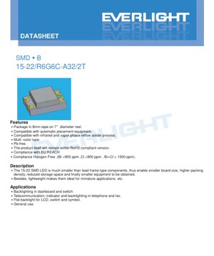
यह दस्तावेज़ एक कॉम्पैक्ट, मल्टी-कलर सरफेस माउंट डिवाइस (एसएमडी) एलईडी के तकनीकी विनिर्देशों का विवरण देता है। यह घटक प्रिंटेड सर्किट बोर्ड पर उच्च-घनत्व माउंटिंग के लिए डिज़ाइन किया गया है, जो अंतिम उपकरण के लघुरूपण को सक्षम बनाता है। इसके हल्के निर्माण और छोटे फॉर्म फैक्टर इसे ऐसे अनुप्रयोगों के लिए उपयुक्त बनाते हैं जहां स्थान और वजन महत्वपूर्ण बाधाएं हैं।
एलईडी सेमीकंडक्टर चिप सामग्री के आधार पर दो अलग-अलग रंग प्रकारों में उपलब्ध है: एक चमकदार लाल (आर6) और एक चमकदार पीला-हरा (जी6)। दोनों प्रकार एक स्पष्ट राल पैकेज में संलग्न हैं। उत्पाद प्रमुख उद्योग मानकों के अनुपालन में है, जिसमें RoHS, EU REACH और हैलोजन-मुक्त आवश्यकताएं शामिल हैं, जो आधुनिक इलेक्ट्रॉनिक विनिर्माण के लिए इसकी उपयुक्तता सुनिश्चित करती हैं।
2. गहन तकनीकी पैरामीटर विश्लेषण
2.1 पूर्ण अधिकतम रेटिंग्स
डिवाइस की परिचालन सीमाएं 25°C के परिवेश के तापमान (Ta) के तहत परिभाषित की गई हैं। इन रेटिंग से अधिक होने पर स्थायी क्षति हो सकती है।
- रिवर्स वोल्टेज (VR): 5 V. यदि रिवर्स वोल्टेज की स्थितियाँ संभव हों तो एक सुरक्षात्मक सर्किट की सिफारिश की जाती है।
- निरंतर फॉरवर्ड करंट (IF): R6 और G6 दोनों चिप्स के लिए 25 mA।
- पीक फॉरवर्ड करंट (IFP): 60 mA, पल्स्ड स्थितियों (1 kHz पर 1/10 ड्यूटी साइकिल) में अनुमेय।
- पावर डिसिपेशन (Pd): 60 mW. यह रेटिंग विद्युत शक्ति के कुल ऊष्मा और प्रकाश में परिवर्तित होने पर विचार करती है।
- इलेक्ट्रोस्टैटिक डिस्चार्ज (ESD): ह्यूमन बॉडी मॉडल (HBM) के अनुसार 2000 V सहन करता है, जो मध्यम हैंडलिंग संवेदनशीलता दर्शाता है। मानक ESD सावधानियाँ आवश्यक हैं।
- तापमान सीमा: संचालन -40°C से +85°C तक; भंडारण -40°C से +90°C तक।
- सोल्डरिंग तापमान: लीड-फ्री रीफ्लो प्रोफाइल (अधिकतम 10 सेकंड के लिए 260°C चरम) और हैंड सोल्डरिंग (अधिकतम 3 सेकंड के लिए 350°C) के साथ संगत।
2.2 विद्युत-प्रकाशीय विशेषताएँ
मुख्य प्रदर्शन पैरामीटर Ta=25°C और 20 mA की फॉरवर्ड करंट (IF) पर मापे जाते हैं, जो मानक परीक्षण स्थिति है।
- प्रदीप्ति तीव्रता (Iv):
- R6 (लाल): सामान्य सीमा 45.0 mcd से 112.0 mcd तक, सहनशीलता ±11%।
- G6 (पीला-हरा): सामान्य सीमा 28.5 mcd से 72.0 mcd तक, सहनशीलता ±11%।
- दृश्य कोण (2θ1/2): एक विस्तृत 140-डिग्री कोण, जो संकेतक और बैकलाइटिंग अनुप्रयोगों के लिए उपयुक्त व्यापक प्रकाश प्रदान करता है।
- तरंगदैर्ध्य:
- R6: शिखर तरंगदैर्ध्य (λp) आमतौर पर 632 nm; प्रमुख तरंगदैर्ध्य (λd) 617.5 nm और 633.5 nm के बीच।
- G6: शिखर तरंगदैर्ध्य (λp) आमतौर पर 575 nm; प्रमुख तरंगदैर्ध्य (λd) 567.5 nm और 577.5 nm के बीच।
- स्पेक्ट्रल बैंडविड्थ (Δλ): दोनों रंगों के लिए लगभग 20 nm, जो स्पेक्ट्रल शुद्धता को परिभाषित करता है।
- फॉरवर्ड वोल्टेज (VF): दोनों चिप प्रकारों के लिए 1.70 V से 2.40 V तक की सीमा में, जिसका विशिष्ट मान 2.00 V है। यह पैरामीटर करंट-लिमिटिंग रेसिस्टर गणना के लिए महत्वपूर्ण है।
- रिवर्स करंट (IR): VR=5V पर अधिकतम 10 μA, जो अच्छी जंक्शन गुणवत्ता को दर्शाता है।
3. बिनिंग प्रणाली स्पष्टीकरण
उत्पादन में एलईडी का चमकदार आउटपुट स्वाभाविक रूप से भिन्न होता है। एक बिनिंग सिस्टम मापी गई प्रदर्शन क्षमता के आधार पर उपकरणों को वर्गीकृत करता है ताकि एक बैच के भीतर एकरूपता सुनिश्चित की जा सके।
3.1 ल्यूमिनस इंटेंसिटी बिनिंग
बिन्स को प्रत्येक चिप प्रकार के लिए IF=20mA पर परिभाषित किया गया है:
- R6 (लाल):
- बिन P: 45.0 mcd (न्यूनतम) से 72.0 mcd (अधिकतम)
- Bin Q: 72.0 mcd (Min) से 112.0 mcd (Max)
- G6 (Yellow-Green):
- Bin N: 28.5 mcd (Min) से 45.0 mcd (Max)
- बिन P: 45.0 mcd (न्यूनतम) से 72.0 mcd (अधिकतम)
यह प्रणाली डिजाइनरों को उनके अनुप्रयोग के लिए उपयुक्त चमक ग्रेड का चयन करने, लागत और प्रदर्शन आवश्यकताओं के बीच संतुलन बनाने की अनुमति देती है।
4. परफॉर्मेंस कर्व एनालिसिस
डेटाशीट में R6 और G6 दोनों प्रकारों के लिए विशिष्ट विशेषता वक्र शामिल हैं। ये ग्राफ़ प्रमुख मापदंडों के बीच संबंध को दृश्य रूप से दर्शाते हैं, जो सर्किट डिजाइन और प्रदर्शन पूर्वानुमान में सहायता करते हैं।
- फॉरवर्ड करंट बनाम फॉरवर्ड वोल्टेज (आई-वी कर्व): ऑपरेटिंग पॉइंट निर्धारित करने और करंट-लिमिटिंग सर्किट्री डिजाइन करने के लिए यह कर्व आवश्यक है। 2.0V का टिपिकल Vf बेसलाइन के रूप में कार्य करता है।
- ल्यूमिनस इंटेंसिटी बनाम फॉरवर्ड करंट: दर्शाता है कि करंट बढ़ने के साथ लाइट आउटपुट कैसे बढ़ता है। अनुशंसित 20mA पर ऑपरेट करने से इष्टतम दक्षता और दीर्घायु सुनिश्चित होती है।
- ल्यूमिनस इंटेंसिटी बनाम एंबिएंट टेम्परेचर: लाइट आउटपुट के थर्मल डिरेटिंग को प्रदर्शित करता है। एंबिएंट तापमान बढ़ने के साथ प्रदर्शन कम हो जाता है, जो सीमित थर्मल मैनेजमेंट वाले डिजाइनों के लिए एक महत्वपूर्ण विचार है।
- स्पेक्ट्रल डिस्ट्रीब्यूशन: तरंग दैर्ध्य के पार सापेक्ष तीव्रता को दर्शाता है, जो पीक और डॉमिनेंट वेवलेंथ मानों और 20nm बैंडविड्थ की पुष्टि करता है।
5. मैकेनिकल और पैकेज इनफॉर्मेशन
5.1 पैकेज डाइमेंशन्स
इस घटक में एक मानक एसएमडी फुटप्रिंट है। आयामी चित्र शरीर का आकार, लीड अंतराल और समग्र ज्यामिति को ±0.1 मिमी के सामान्य सहनशीलता के साथ निर्दिष्ट करता है। पीसीबी पैड डिजाइन और असेंबली के दौरान उचित प्लेसमेंट सुनिश्चित करने के लिए सटीक माप महत्वपूर्ण हैं।
5.2 ध्रुवीयता पहचान
कैथोड की पहचान करने के लिए पैकेज में चिह्न या संरचनात्मक विशेषताएं (जैसे, एक खांचा, एक कटा हुआ कोना, या एक बिंदु) शामिल हैं। उचित सर्किट कार्य सुनिश्चित करने और क्षति को रोकने के लिए प्लेसमेंट के दौरान सही ध्रुवीयता अभिविन्यास अनिवार्य है।
6. सोल्डरिंग और असेंबली दिशानिर्देश
6.1 रीफ्लो सोल्डरिंग प्रोफाइल
एक विस्तृत लीड-मुक्त तापमान प्रोफाइल प्रदान की गई है:
- प्री-हीटिंग: 60–120 सेकंड के लिए 150–200°C.
- लिक्विडस (217°C) से ऊपर का समय: 60–150 सेकंड.
- शीर्ष तापमान: अधिकतम 260°C, 10 सेकंड से अधिक नहीं रखा जाना चाहिए।
- तापन/शीतलन दरें: 255°C से ऊपर अधिकतम 6°C/सेकंड तापन और 3°C/सेकंड शीतलन।
6.2 हैंड सोल्डरिंग
यदि मैन्युअल सोल्डरिंग आवश्यक है:
- 350°C से नीचे टिप तापमान वाले सोल्डरिंग आयरन का उपयोग करें।
- Limit contact time to 3 seconds per terminal.25W या उससे कम की पावर रेटिंग वाले आयरन का उपयोग करें।
- थर्मल स्ट्रेस को रोकने के लिए प्रत्येक टर्मिनल को सोल्डर करने के बीच कम से कम 2-सेकंड का अंतराल दें।
6.3 भंडारण और नमी संवेदनशीलता
डिवाइस को डिसिकेंट के साथ नमी-रोधी बैग में पैक किया गया है।
- उपयोग के लिए तैयार होने तक बैग न खोलें।
- खोलने के बाद, अप्रयुक्त भागों को ≤30°C और ≤60% सापेक्ष आर्द्रता पर संग्रहित किया जाना चाहिए।
- बैग खोलने के बाद "फ्लोर लाइफ" 168 घंटे (7 दिन) है।
- यदि एक्सपोजर समय सीमा से अधिक हो जाता है या डिसिकेंट संतृप्ति दर्शाता है, तो रीफ्लो से पहले 60±5°C पर 24 घंटे के लिए बेक-आउट आवश्यक है।
7. पैकेजिंग और ऑर्डर जानकारी
7.1 मानक पैकेजिंग
एलईडी 7-इंच व्यास के रील पर 8 मिमी चौड़ी वाहक टेप में आपूर्ति की जाती हैं। प्रत्येक रील में 2000 टुकड़े होते हैं। स्वचालित पिक-एंड-प्लेस उपकरणों के साथ संगतता के लिए रील, टेप और कवर टेप के आयाम प्रदान किए जाते हैं।
7.2 लेबल जानकारी
पैकेजिंग लेबल में ट्रेसबिलिटी और पहचान के लिए कई कोड शामिल होते हैं:
- P/N: Product Number (e.g., 15-22/R6G6C-A32/2T).
- मात्रा: पैकिंग मात्रा.
- श्रेणी: Luminous Intensity Rank (Bin Code).
- रंगत: Chromaticity Coordinates & Dominant Wavelength Rank.
- संदर्भ: Forward Voltage Rank.
- LOT No: ट्रेसबिलिटी के लिए निर्माण लॉट नंबर।
8. अनुप्रयोग सिफारिशें
8.1 विशिष्ट अनुप्रयोग परिदृश्य
- बैकलाइटिंग: इसके चौड़े व्यूइंग एंगल के कारण डैशबोर्ड संकेतक, स्विच प्रकाश व्यवस्था और प्रतीक बैकलाइटिंग के लिए आदर्श।
- Telecommunication Equipment: टेलीफोन और फैक्स मशीन जैसे उपकरणों में स्थिति संकेतक और कीपैड बैकलाइटिंग।
- एलसीडी फ्लैट बैकलाइटिंग: छोटे, लो-प्रोफाइल एलसीडी डिस्प्ले के लिए सरणियों में उपयोग किया जा सकता है।
- सामान्य उद्देश्य संकेतन: कोई भी अनुप्रयोग जिसमें एक कॉम्पैक्ट, विश्वसनीय दृश्य संकेतक की आवश्यकता हो।
8.2 महत्वपूर्ण डिज़ाइन विचार
- करंट लिमिटिंग: एक बाहरी श्रृंखला रोकनेवाला है बिल्कुल अनिवार्य. फॉरवर्ड वोल्टेज की एक सीमा (1.7V–2.4V) होती है, और बिना रेसिस्टर के सप्लाई वोल्टेज में एक छोटा सा बदलाव फॉरवर्ड करंट में बड़ा, संभावित रूप से विनाशकारी परिवर्तन पैदा कर सकता है। रेसिस्टर मान (R) की गणना ओम के नियम का उपयोग करके की जाती है: R = (V_supply - Vf_typical) / I_desired। एक रूढ़िवादी डिजाइन के लिए अधिकतम Vf का उपयोग करें।
- थर्मल प्रबंधन: हालांकि पावर डिसिपेशन कम (60mW) है, जंक्शन तापमान को सीमा के भीतर बनाए रखना दीर्घकालिक विश्वसनीयता की कुंजी है। यदि उच्च परिवेश तापमान या उच्च धाराओं पर संचालित किया जा रहा है, तो पर्याप्त PCB कॉपर क्षेत्र या थर्मल वाया सुनिश्चित करें।
- ESD सुरक्षा: हैंडलिंग और असेंबली के दौरान मानक ESD नियंत्रण उपाय लागू करें।
- मरम्मत सीमाएँ: प्रारंभिक सोल्डरिंग के बाद पुनर्कार्य से बचें। यदि बिल्कुल आवश्यक हो, तो पैकेज पर थर्मल स्ट्रेस को कम करने के लिए दोनों टर्मिनलों को एक साथ गर्म करने के लिए डुअल-हेड सोल्डरिंग आयरन का उपयोग करें। मरम्मत के बाद की कार्यक्षमता सत्यापित करें।
9. तकनीकी तुलना और विभेदन
इस घटक के प्राथमिक लाभ पारंपरिक थ्रू-होल एलईडी की तुलना में इसकी एसएमडी पैकेजिंग तकनीक से उत्पन्न होते हैं:
- आकार और घनत्व: काफी छोटे फुटप्रिंट से पीसीबी पर घटकों का घनत्व अधिक होता है, जिससे अंतिम उत्पाद अधिक कॉम्पैक्ट बनते हैं।
- स्वचालन संगतता: टेप-एंड-रील पैकेजिंग उच्च-गति स्वचालित प्लेसमेंट मशीनों के साथ पूरी तरह संगत है, जिससे असेंबली लागत कम होती है और स्थिरता में सुधार होता है।
- वजन: हल्की संरचना पोर्टेबल और लघु अनुप्रयोगों के लिए लाभदायक है।
- प्रक्रिया अनुकूलता: मानक इन्फ्रारेड और वाष्प चरण रीफ्लो सोल्डरिंग प्रक्रियाओं के लिए डिज़ाइन किया गया है, जो आधुनिक, लीड-मुक्त असेंबली लाइनों के साथ संरेखित है।
- बहु-रंग विकल्प: एक ही यांत्रिक पैकेज में दो अलग-अलग रंग (लाल और पीला-हरा) प्रदान करने से डिज़ाइन लचीलापन मिलता है।
10. अक्सर पूछे जाने वाले प्रश्न (FAQ)
10.1 करंट-लिमिटिंग रेसिस्टर की आवश्यकता क्यों है?
एलईडी करंट-चालित उपकरण हैं। उनकी I-V विशेषता घातीय है, जिसका अर्थ है कि फॉरवर्ड वोल्टेज ड्रॉप से आगे वोल्टेज में थोड़ी सी वृद्धि करंट में बहुत अधिक वृद्धि का कारण बनती है, जो तुरंत उपकरण को नष्ट कर सकती है। श्रृंखला रेसिस्टर सर्किट को वोल्टेज-चालित बनाता है, जिससे एक स्थिर और सुरक्षित ऑपरेटिंग करंट निर्धारित होता है।
10.2 क्या मैं इस LED को सीधे 3.3V या 5V माइक्रोकंट्रोलर पिन से चला सकता हूँ?
नहीं। माइक्रोकंट्रोलर के जीपीआईओ पिन की करंट सोर्सिंग/सिंकिंग क्षमता सीमित होती है (अक्सर 20-25mA) और यह लोड को सीधे बिजली देने के लिए डिज़ाइन नहीं किया गया है। भले ही करंट सीमा पर्याप्त लगे, श्रृंखला रोकनेवाला की कमी का मतलब है कि एलईडी के Vf या आपूर्ति वोल्टेज में कोई भी भिन्नता एलईडी और माइक्रोकंट्रोलर दोनों के लिए सुरक्षित सीमा से परे करंट को धकेल सकती है। हमेशा उचित करंट-सीमित रोकनेवाला के साथ ट्रांजिस्टर या ड्राइवर सर्किट का उपयोग करें।
10.3 मेरे डिज़ाइन के लिए "बिनिंग" जानकारी का क्या अर्थ है?
यदि आपके एप्लिकेशन में कई इकाइयों में सुसंगत चमक की आवश्यकता है (जैसे, संकेतकों की एक सरणी में), तो आपको ऑर्डर करते समय वांछित बिन कोड (जैसे, लाल के लिए P या Q) निर्दिष्ट करना चाहिए। एक ही बिन से एलईडी का उपयोग करने से प्रकाश उत्पादन में दृश्यमान भिन्नता न्यूनतम सुनिश्चित होती है। कम महत्वपूर्ण अनुप्रयोगों के लिए, मिश्रित बिन स्वीकार्य और अधिक लागत-प्रभावी हो सकता है।
10.4 मैं नमी संवेदनशीलता निर्देशों की व्याख्या कैसे करूं?
प्लास्टिक एसएमडी पैकेज हवा से नमी अवशोषित कर सकते हैं। रिफ्लो सोल्डरिंग की अधिक गर्मी के दौरान, यह फंसी हुई नमी तेजी से वाष्पित हो सकती है, जिससे आंतरिक परत अलग होना या "पॉपकॉर्निंग" हो सकता है, जिससे पैकेज में दरार पड़ जाती है। सोल्डरिंग से पहले इस नमी को हटाने और असेंबली उपज तथा दीर्घकालिक विश्वसनीयता सुनिश्चित करने के लिए 7-दिवसीय फ्लोर लाइफ और बेकिंग निर्देश महत्वपूर्ण नियंत्रण हैं।
11. व्यावहारिक डिज़ाइन और उपयोग केस
परिदृश्य: एक बहु-स्थिति संकेतक पैनल डिजाइन करना। एक नियंत्रण इकाई को तीन स्वतंत्र स्थिति संकेतकों की आवश्यकता है: पावर (हरा), चेतावनी (पीला), और दोष (लाल)। हालांकि यह डेटाशीट लाल और पीला-हरा कवर करती है, समान डिजाइन सिद्धांत लागू होते हैं।
- सर्किट डिजाइन: 5V सिस्टम और प्रति एलईडी 20mA के लक्ष्य करंट के लिए, रेसिस्टर की गणना करें। 2.0V के विशिष्ट Vf का उपयोग करते हुए: R = (5V - 2.0V) / 0.020A = 150 ओम। मजबूती के लिए, अगला मानक मान चुनें (जैसे, 160 या 180 ओम) और पावर रेटिंग सत्यापित करें (P = I²R = 0.064W, इसलिए 1/8W या 1/10W रेसिस्टर पर्याप्त है)।
- पीसीबी लेआउट: एलईडी को यांत्रिक ड्राइंग के अनुसार रखें। सिल्कस्क्रीन पर ध्रुवीयता चिह्न शामिल करें। थर्मल रिलीफ के लिए, एलईडी पैड को छोटे कॉपर पोर्स से कनेक्ट करें।
- खरीद फॉल्ट के लिए रेड एलईडी (R6) और वॉर्निंग के लिए येलो-ग्रीन (G6) ऑर्डर करें। एक समान रूप सुनिश्चित करने के लिए वांछित चमक बिन (जैसे, दोनों के लिए बिन P) निर्दिष्ट करें।
- असेंबली रीफ्लो प्रोफाइल का सटीकता से पालन करें। यदि 7 दिनों के भीतर उपयोग नहीं किया जाता है, तो खुले रील्स को सूखे कैबिनेट में संग्रहित करें।
12. तकनीकी सिद्धांत परिचय
इन एलईडी में प्रकाश उत्सर्जन AlGaInP (एल्युमिनियम गैलियम इंडियम फॉस्फाइड) अर्धचालक सामग्री प्रणाली पर आधारित है। जब p-n जंक्शन पर एक फॉरवर्ड वोल्टेज लगाया जाता है, तो इलेक्ट्रॉन और होल सक्रिय क्षेत्र में इंजेक्ट होते हैं जहां वे पुनर्संयोजित होते हैं। इस पुनर्संयोजन प्रक्रिया के दौरान मुक्त ऊर्जा फोटॉन (प्रकाश) के रूप में उत्सर्जित होती है। AlGaInP मिश्र धातु की विशिष्ट संरचना बैंडगैप ऊर्जा निर्धारित करती है, जो सीधे उत्सर्जित प्रकाश की तरंगदैर्ध्य (रंग) को परिभाषित करती है। R6 चिप लाल उत्सर्जन (~632 nm) के लिए इंजीनियर की गई है, जबकि G6 चिप पीले-हरे उत्सर्जन (~575 nm) के लिए ट्यून की गई है। स्पष्ट रेजिन पैकेज एक लेंस के रूप में कार्य करता है, जो 140-डिग्री व्यूइंग एंगल को आकार देता है और पर्यावरणीय सुरक्षा प्रदान करता है।
13. उद्योग रुझान और विकास
इस घटक जैसे एसएमडी एलईडी के लिए बाजार लघुकरण, उच्च दक्षता और ठोस-राज्य प्रकाश व्यवस्था के व्यापक अपनाने की मांगों द्वारा प्रेरित बना हुआ है। इस उत्पाद खंड को प्रभावित करने वाले प्रमुख रुझानों में शामिल हैं:
- बढ़ी हुई दक्षता: निरंतर सामग्री विज्ञान और चिप डिजाइन सुधारों का लक्ष्य समान या कम ड्राइव धाराओं पर उच्च दीप्त तीव्रता (एमसीडी) प्रदान करना है, जिससे समग्र प्रणाली ऊर्जा दक्षता में सुधार होता है।
- बढ़ी हुई विश्वसनीयता: पैकेजिंग सामग्री और डाई-अटैच प्रौद्योगिकियों में प्रगति का ध्यान थर्मल प्रदर्शन और दीर्घायु में सुधार पर केंद्रित है, विशेष रूप से कठोर वातावरण या उच्च तापमान पर संचालन के लिए।
- मानकीकरण और स्वचालन: मानकीकृत पैकेज फुटप्रिंट और टेप प्रारूपों की ओर बढ़ना स्वचालित असेंबली प्रक्रियाओं को सुव्यवस्थित करना जारी रखता है, जिससे विनिर्माण लागत कम होती है।
- व्यापक रंग सीमा और एकरूपता: तरंगदैर्ध्य और ज्योति फ्लक्स दोनों के लिए सख्त बिनिंग सहनशीलताएं अधिक सामान्य होती जा रही हैं, जो उच्च रंग एकरूपता वाले अनुप्रयोगों को सक्षम बनाती हैं, जैसे पूर्ण-रंग डिस्प्ले और परिष्कृत संकेतक प्रणालियाँ।
- एकीकरण: एलईडी पैकेजों के भीतर नियंत्रण सर्किटरी (जैसे निरंतर धारा ड्राइवर या पीडब्ल्यूएम नियंत्रक) को एकीकृत करने की प्रवृत्ति मौजूद है, हालांकि सरल संकेतक प्रकारों के लिए, लागत और लचीलेपन के कारण असतत घटक दृष्टिकोण प्रमुख बना हुआ है।
यह घटक एक परिपक्व, सुस्थापित प्रौद्योगिकी का प्रतिनिधित्व करता है जो संकेतक और बैकलाइट अनुप्रयोगों की एक विस्तृत श्रृंखला के लिए प्रदर्शन, लागत और विनिर्माण क्षमता के बीच संतुलन बनाता है।
LED विनिर्देशन शब्दावली
Complete explanation of LED technical terms
प्रकाशविद्युत प्रदर्शन
| पद | इकाई/प्रतिनिधित्व | सरल व्याख्या | महत्वपूर्ण क्यों |
|---|---|---|---|
| Luminous Efficacy | lm/W (lumens per watt) | प्रति वाट बिजली से प्रकाश उत्पादन, उच्च मान का अर्थ है अधिक ऊर्जा कुशल। | सीधे ऊर्जा दक्षता ग्रेड और बिजली लागत निर्धारित करता है। |
| Luminous Flux | lm (lumens) | स्रोत द्वारा उत्सर्जित कुल प्रकाश, जिसे आमतौर पर "चमक" कहा जाता है। | प्रकाश पर्याप्त चमकदार है या नहीं, यह निर्धारित करता है। |
| देखने का कोण | ° (डिग्री), उदाहरण के लिए, 120° | वह कोण जहाँ प्रकाश की तीव्रता आधी रह जाती है, यह बीम की चौड़ाई निर्धारित करता है। | प्रकाश के दायरे और एकरूपता को प्रभावित करता है। |
| CCT (Color Temperature) | K (Kelvin), उदाहरणार्थ, 2700K/6500K | प्रकाश की गरमाहट/ठंडक, कम मान पीलेपन/गर्म स्वर, अधिक मान सफेदी/ठंडे स्वर का संकेत देते हैं। | प्रकाश व्यवस्था का वातावरण और उपयुक्त परिदृश्य निर्धारित करता है। |
| CRI / Ra | इकाईहीन, 0–100 | वस्तुओं के रंगों को सटीक रूप से प्रदर्शित करने की क्षमता, Ra≥80 अच्छा माना जाता है। | रंग की प्रामाणिकता को प्रभावित करता है, मॉल, संग्रहालय जैसे उच्च मांग वाले स्थानों में प्रयोग किया जाता है। |
| SDCM | मैकएडम दीर्घवृत्त चरण, उदाहरण के लिए, "5-चरण" | रंग एकरूपता मापक, छोटे चरणों का अर्थ है अधिक सुसंगत रंग। | एलईडी के एक ही बैच में समान रंग सुनिश्चित करता है। |
| Dominant Wavelength | nm (nanometers), jaise, 620nm (laal) | Rangin LEDs ke rang ke anukool wavelength. | Laal, peele, hare monochrome LEDs ke rang ka hue nirdhaarit karta hai. |
| Spectral Distribution | Wavelength vs intensity curve | Wavelengths par intensity ke vitaran ko dikhata hai. | रंग प्रतिपादन और गुणवत्ता को प्रभावित करता है। |
विद्युत मापदंड
| पद | Symbol | सरल व्याख्या | Design Considerations |
|---|---|---|---|
| Forward Voltage | Vf | एलईडी चालू करने के लिए न्यूनतम वोल्टेज, जैसे "प्रारंभिक सीमा"। | ड्राइवर वोल्टेज ≥Vf होना चाहिए, श्रृंखला एलईडी के लिए वोल्टेज जुड़ते हैं। |
| फॉरवर्ड करंट | If | सामान्य एलईडी संचालन के लिए करंट मान। | Usually constant current drive, current determines brightness & lifespan. |
| अधिकतम पल्स धारा | Ifp | छोटी अवधि के लिए सहनीय शिखर धारा, जिसका उपयोग डिमिंग या फ्लैशिंग के लिए किया जाता है। | Pulse width & duty cycle must be strictly controlled to avoid damage. |
| रिवर्स वोल्टेज | Vr | एलईडी सहन कर सकने वाला अधिकतम रिवर्स वोल्टेज, इससे अधिक होने पर ब्रेकडाउन हो सकता है। | सर्किट को रिवर्स कनेक्शन या वोल्टेज स्पाइक्स को रोकना चाहिए। |
| Thermal Resistance | Rth (°C/W) | चिप से सोल्डर तक ऊष्मा हस्तांतरण के लिए प्रतिरोध, कम होना बेहतर है। | उच्च थर्मल प्रतिरोध के लिए मजबूत हीट डिसिपेशन की आवश्यकता होती है। |
| ESD Immunity | V (HBM), e.g., 1000V | Ability to withstand electrostatic discharge, higher means less vulnerable. | Anti-static measures needed in production, especially for sensitive LEDs. |
Thermal Management & Reliability
| पद | Key Metric | सरल व्याख्या | प्रभाव |
|---|---|---|---|
| जंक्शन तापमान | Tj (°C) | एलईडी चिप के अंदर का वास्तविक कार्य तापमान। | प्रत्येक 10°C कमी जीवनकाल को दोगुना कर सकती है; बहुत अधिक तापमान प्रकाश क्षय, रंग परिवर्तन का कारण बनता है। |
| लुमेन मूल्यह्रास | L70 / L80 (घंटे) | प्रारंभिक चमक के 70% या 80% तक गिरने में लगा समय। | सीधे तौर पर LED की "सेवा जीवन" को परिभाषित करता है। |
| लुमेन रखरखाव | % (उदाहरण: 70%) | समय के बाद बची हुई चमक का प्रतिशत। | दीर्घकालिक उपयोग के दौरान चमक बनाए रखने को दर्शाता है। |
| रंग परिवर्तन | Δu′v′ or MacAdam ellipse | उपयोग के दौरान रंग परिवर्तन की मात्रा। | प्रकाश व्यवस्था के दृश्यों में रंग स्थिरता को प्रभावित करता है। |
| Thermal Aging | सामग्री क्षरण | दीर्घकालिक उच्च तापमान के कारण ह्रास। | इससे चमक में कमी, रंग परिवर्तन, या ओपन-सर्किट विफलता हो सकती है। |
Packaging & Materials
| पद | सामान्य प्रकार | सरल व्याख्या | Features & Applications |
|---|---|---|---|
| पैकेज प्रकार | EMC, PPA, सिरेमिक | चिप की सुरक्षा करने वाला आवास सामग्री, प्रकाशीय/तापीय इंटरफेस प्रदान करता है। | EMC: अच्छी ऊष्मा प्रतिरोधकता, कम लागत; सिरेमिक: बेहतर ऊष्मा अपव्यय, लंबी आयु। |
| चिप संरचना | फ्रंट, फ्लिप चिप | चिप इलेक्ट्रोड व्यवस्था। | फ्लिप चिप: बेहतर ताप अपव्यय, उच्चतर दक्षता, उच्च-शक्ति के लिए। |
| फॉस्फर कोटिंग | YAG, सिलिकेट, नाइट्राइड | नीले चिप को ढकता है, कुछ को पीले/लाल में परिवर्तित करता है, सफेद रंग में मिलाता है। | विभिन्न फॉस्फर दक्षता, CCT, और CRI को प्रभावित करते हैं। |
| लेंस/ऑप्टिक्स | फ्लैट, माइक्रोलेंस, TIR | सतह पर प्रकाश वितरण को नियंत्रित करने वाली प्रकाशीय संरचना। | दृश्य कोण और प्रकाश वितरण वक्र निर्धारित करता है। |
Quality Control & Binning
| पद | बिनिंग सामग्री | सरल व्याख्या | उद्देश्य |
|---|---|---|---|
| Luminous Flux Bin | Code e.g., 2G, 2H | चमक के आधार पर समूहीकृत, प्रत्येक समूह के न्यूनतम/अधिकतम लुमेन मान होते हैं। | एक ही बैच में समान चमक सुनिश्चित करता है। |
| Voltage Bin | कोड उदाहरणार्थ, 6W, 6X | फॉरवर्ड वोल्टेज रेंज के अनुसार समूहीकृत। | ड्राइवर मिलान को सुगम बनाता है, सिस्टम दक्षता में सुधार करता है। |
| कलर बिन | 5-step MacAdam ellipse | रंग निर्देशांक के अनुसार समूहीकृत, एक सघन सीमा सुनिश्चित करते हुए। | रंग स्थिरता की गारंटी देता है, फिक्स्चर के भीतर असमान रंग से बचाता है। |
| CCT Bin | 2700K, 3000K इत्यादि। | CCT के अनुसार समूहीकृत, प्रत्येक की संबंधित निर्देशांक सीमा होती है। | विभिन्न दृश्य CCT आवश्यकताओं को पूरा करता है। |
Testing & Certification
| पद | Standard/Test | सरल व्याख्या | Significance |
|---|---|---|---|
| LM-80 | Lumen maintenance test | निरंतर तापमान पर दीर्घकालिक प्रकाश व्यवस्था, चमक क्षय का रिकॉर्डिंग। | LED जीवन का अनुमान लगाने के लिए उपयोग किया जाता है (TM-21 के साथ)। |
| TM-21 | जीवन अनुमान मानक | LM-80 डेटा के आधार पर वास्तविक परिस्थितियों में जीवन का अनुमान लगाता है। | वैज्ञानिक जीवन पूर्वानुमान प्रदान करता है। |
| IESNA | Illuminating Engineering Society | प्रकाशिक, विद्युतीय, तापीय परीक्षण विधियों को शामिल करता है। | उद्योग-मान्यता प्राप्त परीक्षण आधार। |
| RoHS / REACH | पर्यावरणीय प्रमाणन। | हानिकारक पदार्थों (सीसा, पारा) की अनुपस्थिति सुनिश्चित करता है। | अंतरराष्ट्रीय स्तर पर बाजार पहुंच की आवश्यकता। |
| ENERGY STAR / DLC | ऊर्जा दक्षता प्रमाणन | प्रकाश व्यवस्था के लिए ऊर्जा दक्षता और प्रदर्शन प्रमाणन। | सरकारी खरीद, सब्सिडी कार्यक्रमों में उपयोग किया जाता है, प्रतिस्पर्धात्मकता बढ़ाता है। |