विषय-सूची
- 1. Product Overview
- 1.1 Core Advantages and Positioning
- 1.2 लक्षित अनुप्रयोग
- 2. तकनीकी पैरामीटर विश्लेषण
- 2.1 Absolute Maximum Ratings
- 2.2 इलेक्ट्रो-ऑप्टिकल विशेषताएँ
- 2.3 थर्मल और सोल्डरिंग विशेषताएँ
- 3. बिनिंग सिस्टम स्पष्टीकरण
- 3.1 ल्यूमिनस फ्लक्स बिनिंग
- 3.2 Forward Voltage Binning
- 3.3 क्रोमैटिसिटी और कलर टेम्परेचर बिनिंग
- 3.4 कलर रेंडरिंग इंडेक्स (CRI) इंडेक्स
- 4. उत्पाद क्रमांकन और ऑर्डरिंग गाइड
- 4.1 पार्ट नंबर स्पष्टीकरण
- 4.2 बड़े पैमाने पर उत्पादन सूची
- 5. Application Guidelines and Design Considerations
- 5.1 Typical Application Scenarios
- 5.2 Driver Circuit Design
- 5.3 Thermal Management Design
- 5.4 ऑप्टिकल डिज़ाइन विचार
- 6. Performance Curves and Chromaticity Analysis
- 6.1 Interpreting the Chromaticity Diagrams
- 7. तुलना और चयन का तर्क
- 8. अक्सर पूछे जाने वाले प्रश्न (FAQ)
- 9. तकनीकी सिद्धांत और रुझान
- 9.1 Operating Principle
- 9.2 Industry Trends
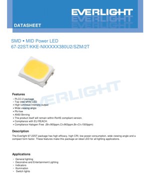
1. Product Overview
The 67-22ST एक सरफेस-माउंट डिवाइस (SMD) मिड-पावर LED है जो एक PLCC-2 (प्लास्टिक लीडेड चिप कैरियर) पैकेज में रखा गया है। इसे एक सफेद LED समाधान के रूप में डिज़ाइन किया गया है जो प्रदर्शन, दक्षता और कॉम्पैक्ट फॉर्म फैक्टर का संतुलन प्रदान करता है, जिससे यह प्रकाश व्यवस्था के उन व्यापक अनुप्रयोगों के लिए उपयुक्त है जिनके लिए विश्वसनीय और सुसंगत प्रकाश उत्पादन की आवश्यकता होती है।
1.1 Core Advantages and Positioning
This LED package is characterized by several key advantages that position it as a versatile component in the lighting market. It delivers high luminous intensity output, ensuring bright and effective illumination. The device features a wide viewing angle, typically 120 degrees, which promotes even light distribution and is ideal for applications requiring broad-area coverage. Furthermore, it is constructed using lead-free (Pb-free) materials and complies with major environmental and safety regulations including RoHS, EU REACH, and halogen-free standards (with Bromine <900ppm, Chlorine <900ppm, Br+Cl <1500ppm). The use of ANSI-standard binning for color characteristics ensures consistency and predictability in color performance across production batches.
1.2 लक्षित अनुप्रयोग
उच्च दक्षता, अच्छा कलर रेंडरिंग इंडेक्स (CRI), कम बिजली खपत और एक कॉम्पैक्ट फुटप्रिंट का संयोजन इस एलईडी को कई अनुप्रयोगों के लिए उपयुक्त बनाता है। प्राथमिक उपयोग के मामलों में सामान्य प्रयोजन प्रकाश व्यवस्था, सजावटी और मनोरंजन प्रकाश व्यवस्था, स्थिति संकेतक, विभिन्न प्रकाश व्यवस्था कार्य और स्विच बैकलाइटिंग शामिल हैं।
2. तकनीकी पैरामीटर विश्लेषण
यह खंड मानक परीक्षण स्थितियों (सोल्डरिंग बिंदु तापमान 25°C पर) के तहत डेटाशीट में परिभाषित एलईडी की प्रमुख तकनीकी विशिष्टताओं की विस्तृत, वस्तुनिष्ठ व्याख्या प्रदान करता है।
2.1 Absolute Maximum Ratings
Absolute Maximum Ratings उन सीमाओं को परिभाषित करते हैं जिनके परे डिवाइस को स्थायी क्षति हो सकती है। ये सामान्य संचालन के लिए अभिप्रेत नहीं हैं।
- फॉरवर्ड करंट (IF): 36 mA (निरंतर)
- पीक फॉरवर्ड करंट (IFP): 72 mA (Pulsed, Duty Cycle 1/10, Pulse Width 10ms)
- Power Dissipation (Pd): 1368 mW
- Operating Temperature (Topr): -40°C से +85°C
- भंडारण तापमान (Tstg): -40°C से +100°C
- थर्मल रेज़िस्टेंस, जंक्शन से सोल्डरिंग पॉइंट (Rth J-S): 16 °C/W
- Maximum Junction Temperature (Tj): 115 °C
Important Note: यह उपकरण इलेक्ट्रोस्टैटिक डिस्चार्ज (ESD) के प्रति संवेदनशील है। अव्यक्त या विनाशकारी विफलता को रोकने के लिए असेंबली और हैंडलिंग के दौरान उचित ESD हैंडलिंग प्रक्रियाओं का पालन किया जाना चाहिए।
2.2 इलेक्ट्रो-ऑप्टिकल विशेषताएँ
ये पैरामीटर 25 mA की विशिष्ट ऑपरेटिंग फॉरवर्ड करंट पर मापे जाते हैं।
- Luminous Flux (Φ): न्यूनतम ल्यूमिनस फ्लक्स 120 lm निर्दिष्ट है, जिसकी विशिष्ट सहनशीलता ±11% है। वास्तविक फ्लक्स मान विशिष्ट बिन कोड (जैसे, S3A, S3B, आदि) पर निर्भर करता है।
- Forward Voltage (VF): 25mA पर न्यूनतम 34 V से अधिकतम 38 V तक की सीमा है। विशिष्ट सहनशीलता ±0.1V है, और सख्त नियंत्रण के लिए विशिष्ट वोल्टेज बिन (C4 से C7) परिभाषित किए गए हैं।
- Color Rendering Index (CRI/Ra): न्यूनतम CRI 80 की गारंटी है, जिसकी सहनशीलता ±2 है। R9 मान (संतृप्त लाल) न्यूनतम 0 निर्दिष्ट किया गया है।
- Viewing Angle (2θ1/2): अर्ध-तीव्रता कोण आमतौर पर 120 डिग्री होता है।
2.3 थर्मल और सोल्डरिंग विशेषताएँ
उचित थर्मल प्रबंधन एलईडी की दीर्घायु और प्रदर्शन रखरखाव के लिए महत्वपूर्ण है।
- 16 °C/W का थर्मल प्रतिरोध प्रति वाट विद्युत क्षय पर जंक्शन से सोल्डर बिंदु तक तापमान वृद्धि को दर्शाता है। गर्मी प्रबंधन के लिए प्रभावी पीसीबी लेआउट और संभावित थर्मल वाया के उपयोग की सिफारिश की जाती है।
- Reflow Solderingएलईडी 260°C के शिखर तापमान को अधिकतम 10 सेकंड तक सहन कर सकती है।
- हाथ से सोल्डरिंगयदि आवश्यक हो, तो 350°C के सोल्डरिंग आयरन टिप को अधिकतम 3 सेकंड के लिए लगाया जा सकता है।
3. बिनिंग सिस्टम स्पष्टीकरण
उत्पाद प्रमुख प्रदर्शन भिन्नताओं को वर्गीकृत करने के लिए एक व्यापक बिनिंग सिस्टम का उपयोग करता है, जिससे डिजाइनर अपने अनुप्रयोग के लिए सुसंगत विशेषताओं वाले एलईडी का चयन कर सकते हैं।
3.1 ल्यूमिनस फ्लक्स बिनिंग
Luminous flux is grouped into bins denoted by codes like S3A, S3B, S4A, etc. Each bin defines a minimum and maximum flux range measured at IF=25mA. For example, bin S3A covers 120 to 125 lm, and S3B covers 125 to 130 lm. This allows for selection based on brightness requirements.
3.2 Forward Voltage Binning
Forward voltage is binned to aid in circuit design, particularly for driving multiple LEDs in series. Bins range from C4 (34.0-35.0V) to C7 (37.0-38.0V). Selecting LEDs from the same or adjacent voltage bins can help ensure more uniform current distribution in parallel strings or predictable voltage requirements in series strings.
3.3 क्रोमैटिसिटी और कलर टेम्परेचर बिनिंग
डेटाशीट 2700K और 3000K जैसे विभिन्न कोरिलेटेड कलर टेम्परेचर (CCT) के लिए विस्तृत क्रोमैटिसिटी कोऑर्डिनेट (CIE x, y) बॉक्स प्रदान करती है। कई बिनिंग योजनाएं प्रस्तुत की गई हैं:
- 3-स्टेप और 5-स्टेप मैकएडम दीर्घवृत्त: ये अधिक कड़े रंग स्थिरता को परिभाषित करते हैं। एक "3-STEP" बिन यह सुनिश्चित करता है कि सभी LEDs एक 3-स्टेप MacAdam दीर्घवृत्त के भीतर आते हैं, जो बहुत छोटे रंग भिन्नता का प्रतिनिधित्व करता है जो केवल सावधानीपूर्वक तुलना के तहत ही ध्यान देने योग्य होती है। "5-STEP" थोड़ा ढीला है लेकिन अधिकांश अनुप्रयोगों के लिए अच्छी रंग एकरूपता सुनिश्चित करता है।
- Detailed 7-Code Chromaticity Bins: प्रत्येक CCT (जैसे, 2700K) के लिए, 27-7A, 27-7B आदि जैसे कोड में आगे उपविभाजन, विशिष्ट निर्देशांक कोनों और संदर्भ CCT रेंज (जैसे, 2580K~2718K) के साथ प्रदान किया जाता है। यह महत्वपूर्ण अनुप्रयोगों में अत्यधिक सटीक रंग मिलान की अनुमति देता है।
3.4 कलर रेंडरिंग इंडेक्स (CRI) इंडेक्स
CRI को पार्ट नंबर में एक अक्षर द्वारा दर्शाया जाता है (उदाहरण के लिए, CRI 80 Min. के लिए 'K')। तालिका M (CRI 60 Min.) से H (CRI 90 Min.) तक के प्रतीकों को परिभाषित करती है, जिसमें उदाहरण पार्ट्स सभी न्यूनतम CRI 80 के लिए 'K' का उपयोग करते हैं।
4. उत्पाद क्रमांकन और ऑर्डरिंग गाइड
4.1 पार्ट नंबर स्पष्टीकरण
भाग संख्या एक संरचित प्रारूप का अनुसरण करती है: 67-22ST/KKE-NXX XX XX 380U2/SZM/2T
- 67-22ST/: आधार पैकेज प्रकार।
- K: CRI बिन कोड (K = 80 मिनट)।
- KE: संभावित आंतरिक कोड।
- N: CRI सूचकांक (N=65 न्यूनतम, लेकिन इस मामले में 'K' द्वारा ओवरराइड? उदाहरण KKE-N... का उपयोग करता है)। उदाहरण स्पष्ट करता है कि 'K' CRI=80 परिभाषित करता है।
- First XX: Color Temperature in hundreds of Kelvin (e.g., 27 for 2700K).
- Second XX: Luminous Flux code (e.g., 12 for 120 lm min).
- Third XX: संभवतः एक फ्लक्स या रंग उप-बिन।
- 380: फॉरवर्ड वोल्टेज इंडेक्स (38.0V अधिकतम)।
- U2: फॉरवर्ड करंट इंडेक्स (IF=25mA).
- /SZM/2T: पैकेजिंग और टेप विनिर्देश।
उदाहरण: 67-22ST/KKE-N27120380U2/SZM/2T का डिकोड: CRI 80 Min., CCT 2700K, Flux 120 lm min, VF 38.0V अधिकतम, IF 25mA.
4.2 बड़े पैमाने पर उत्पादन सूची
The datasheet lists specific part numbers available for mass production, covering popular CCTs at a minimum CRI of 80:
- 2700K (120 lm min)
- 3000K (125 lm min)
- 4000K (130 lm min)
- 5000K (130 lm min)
- 6500K (130 lm min)
5. Application Guidelines and Design Considerations
5.1 Typical Application Scenarios
इसकी विशिष्टताओं के आधार पर, यह LED निम्नलिखित के लिए उपयुक्त है:
- सामान्य इनडोर प्रकाश व्यवस्था: इसकी 2700K-6500K CCT रेंज और अच्छा CRI इसे घरों, कार्यालयों और खुदरा स्थानों में परिवेश प्रकाश व्यवस्था के लिए उपयुक्त बनाता है, खासकर जब एलईडी मॉड्यूल या स्ट्रिप्स पर सरणियों में उपयोग किया जाता है।
- Decorative & Architectural Lighting: विस्तृत दृश्य कोण और सुसंगत रंग बिन्स कोव्स, शेल्फ़, साइनेज और फ़ैसाड लाइटिंग के लिए आदर्श हैं जहाँ समान प्रकाश फैलाव वांछित है।
- कार्यात्मक प्रकाश व्यवस्था: इसकी चमक और रंग गुणवत्ता के लाभकारी होने के कारण टास्क लाइट्स, कैबिनेट लाइटिंग या अंडर-कैबिनेट लाइटिंग में उपयोग किया जा सकता है।
5.2 Driver Circuit Design
उच्च फॉरवर्ड वोल्टेज (25mA पर 34-38V) को देखते हुए, एक कॉन्स्टेंट-करंट LED ड्राइवर आवश्यक है। ड्राइवर को आवश्यक करंट प्रदान करने के लिए रेटेड होना चाहिए, साथ ही LED स्ट्रिंग(स) के कुल फॉरवर्ड वोल्टेज को समायोजित करना चाहिए। एकल LED के लिए, ड्राइवर आउटपुट वोल्टेज ~38V से अधिक होना चाहिए। श्रृंखला में जुड़े कई LEDs के लिए, कुल VF जुड़ जाता है (उदाहरण के लिए, 3 LEDs को ~102-114V की आवश्यकता हो सकती है), जो ड्राइवर चयन को प्रभावित करता है। कम करंट (25mA) कुशल ड्राइवर डिज़ाइन और उचित बैलास्टिंग के साथ एकल करंट-रेगुलेटेड स्रोत से कई समानांतर स्ट्रिंग्स चलाने की संभावना की अनुमति देता है।
5.3 Thermal Management Design
~0.95W (38V * 0.025A) तक की विद्युत क्षय और 16°C/W के तापीय प्रतिरोध के साथ, सोल्डर बिंदु से जंक्शन तापमान में वृद्धि महत्वपूर्ण हो सकती है। उदाहरण के लिए, यदि सोल्डर बिंदु 60°C तक पहुँचता है, तो जंक्शन 60°C + (0.95W * 16°C/W) = ~75°C पर हो सकता है, जो सीमा के भीतर है लेकिन प्रकाश उत्पादन और जीवनकाल को कम कर देता है। इसलिए, पर्याप्त तांबे के क्षेत्र (हीट सिंक के रूप में कार्य करते हुए) के साथ PCB डिजाइन करना और अंतिम फिक्स्चर में अच्छे वायु प्रवाह को सुनिश्चित करना प्रदर्शन और दीर्घायु बनाए रखने के लिए महत्वपूर्ण है।
5.4 ऑप्टिकल डिज़ाइन विचार
120-डिग्री का देखने का कोण स्वाभाविक रूप से चौड़ा होता है। अधिक केंद्रित बीम की आवश्यकता वाले अनुप्रयोगों के लिए, लेंस या परावर्तक जैसे द्वितीयक प्रकाशिकी आवश्यक होंगे। पैकेज का वाटर-क्लियर रेजिन महत्वपूर्ण अवशोषण हानि के बिना ऐसी प्रकाशिकी के साथ उपयोग के लिए उपयुक्त है।
6. Performance Curves and Chromaticity Analysis
डेटाशीट में 2700K और 3000K के लिए प्लॉटेड बिन रेंज के साथ CIE 1931 क्रोमैटिसिटी डायग्राम शामिल हैं। रंग बिंदु भिन्नता को समझने के लिए ये डायग्राम महत्वपूर्ण हैं।
6.1 Interpreting the Chromaticity Diagrams
ब्लैक-बॉडी लोकस (वक्र रेखा) विभिन्न तापमानों पर एक सैद्धांतिक परफेक्ट रेडिएटर के रंग का प्रतिनिधित्व करती है। बिन (आयत या समांतर चतुर्भुज) किसी दिए गए CCT बिन के लिए रंग निर्देशांक (x,y) के स्वीकार्य प्रसार को दर्शाते हैं। एक सख्त बिन (जैसे, 3-STEP) चुनने से सभी एलईडी मानव आंख को रंग में लगभग समान दिखाई देंगी, जो उच्च-गुणवत्ता वाले प्रकाश उत्पादों के लिए महत्वपूर्ण है जहां रंग बेमेल अस्वीकार्य है। प्रदान किए गए निर्देशांक कोनों से बहु-एलईडी प्रणालियों में सटीक रंग मिश्रण गणना की अनुमति मिलती है।
7. तुलना और चयन का तर्क
पारंपरिक थ्रू-होल एलईडी की तुलना में, यह एसएमडी पैकेज स्वचालित असेंबली, पीसीबी तक तापीय पथ और डिज़ाइन लघुकरण में महत्वपूर्ण लाभ प्रदान करता है। एसएमडी मध्य-शक्ति खंड के भीतर, इसके प्रमुख अंतर इसका अपेक्षाकृत उच्च फॉरवर्ड वोल्टेज (जो सुझाव देता है कि इसमें पैकेज के भीतर श्रृंखला में कई डाई हो सकते हैं) और सख्त क्रोमैटिसिटी बिनिंग विकल्पों की उपलब्धता हैं। यह इसे मध्यम शक्ति स्तर पर अच्छे रंग स्थिरता की आवश्यकता वाले अनुप्रयोगों में प्रतिस्पर्धी बनाता है, जो कम-शक्ति संकेतक एलईडी और उच्च-शक्ति प्रकाश एलईडी के बीच की खाई को पाटता है।
8. अक्सर पूछे जाने वाले प्रश्न (FAQ)
Q: इस एलईडी के लिए सामान्य संचालन धारा क्या है?
A: डेटाशीट I=25mA पर विद्युत-प्रकाशीय विशेषताएँ निर्दिष्ट करती है, जो अनुशंसित सामान्य संचालन धारा है।Fइसे निरपेक्ष अधिकतम रेटिंग 36mA सतत तक संचालित किया जा सकता है, लेकिन इससे ऊष्मा बढ़ेगी और जीवनकाल व दक्षता कम हो सकती है।
Q: ±11% के दीप्त प्रवाह सहनशीलता की व्याख्या कैसे करूं?
A: इसका मतलब है कि किसी दिए गए एलईडी का वास्तविक चमकदार फ्लक्स नाममात्र बिन मूल्य से ±11% तक भिन्न हो सकता है। उदाहरण के लिए, 120 एलएम न्यूनतम बिन वाला एक एलईडी वास्तव में लगभग 107 एलएम और 133 एलएम के बीच माप सकता है। लगातार चमक के लिए, एक ही उत्पादन लॉट से सोर्स करने की सलाह दी जाती है।
Q: क्या मैं इस एलईडी को सीधे एक स्थिर वोल्टेज स्रोत से चला सकता हूं?
A: नहीं। एलईडी करंट-चालित उपकरण हैं। उनका फॉरवर्ड वोल्टेज एक सहनशीलता रखता है और तापमान के साथ बदलता रहता है। एक स्थिर-वोल्टेज आपूर्ति से अनियंत्रित करंट होगा, संभावित रूप से अधिकतम रेटिंग से अधिक हो सकता है और एलईडी को नष्ट कर सकता है। हमेशा एक स्थिर-करंट ड्राइवर या करंट-लिमिटिंग सर्किट का उपयोग करें।
Q: मेरे अनुप्रयोग के लिए "हैलोजन-मुक्त" अनुपालन का क्या अर्थ है?
A: हैलोजन-मुक्त सामग्री आग लगने की स्थिति में विषैले और संक्षारक धुएं (जैसे डाइऑक्सिन) के उत्सर्जन को कम करती है। यह उपभोक्ता इलेक्ट्रॉनिक्स, इनडोर लाइटिंग और विशिष्ट पर्यावरणीय या सुरक्षा प्रमाणपत्रों वाले उत्पादों (जैसे, बंद सार्वजनिक स्थानों में उपयोग के लिए) के लिए तेजी से महत्वपूर्ण होता जा रहा है।
9. तकनीकी सिद्धांत और रुझान
9.1 Operating Principle
यह एलईडी अर्धचालक प्रौद्योगिकी पर आधारित है। जब इसके बैंडगैप ऊर्जा से अधिक का फॉरवर्ड वोल्टेज लगाया जाता है, तो इलेक्ट्रॉन और होल InGaN (इंडियम गैलियम नाइट्राइड) चिप के सक्रिय क्षेत्र के भीतर पुनर्संयोजित होते हैं, जिससे फोटॉन (प्रकाश) के रूप में ऊर्जा मुक्त होती है। अर्धचालक परतों की विशिष्ट संरचना और फॉस्फर (सफेद एलईडी के लिए) का उपयोग उत्सर्जित प्रकाश की तरंगदैर्ध्य और रंग निर्धारित करते हैं। PLCC-2 पैकेज यांत्रिक सुरक्षा, विद्युत कनेक्शन और एक प्राथमिक ऑप्टिकल लेंस प्रदान करता है, साथ ही मुद्रित सर्किट बोर्ड तक ऊष्मा स्थानांतरण को सुविधाजनक बनाता है।
9.2 Industry Trends
मध्यम-शक्ति एलईडी खंड उच्च दक्षता (प्रति वाट अधिक लुमेन), बेहतर रंग प्रतिपादन (उच्च आर9 मान, पूर्ण स्पेक्ट्रम), और अधिक विश्वसनीयता की ओर विकसित हो रहा है। डिजाइन और सोर्सिंग को सरल बनाने के लिए फुटप्रिंट और फोटोमेट्रिक डेटा के मानकीकरण की भी एक मजबूत प्रवृत्ति है। इस डेटाशीट में देखे गए विस्तृत क्रोमैटिसिटी और फ्लक्स बिनिंग का समावेश, बड़े पैमाने पर उत्पादन में पूर्वानुमेय प्रदर्शन और रंग स्थिरता के लिए बाजार की मांग को दर्शाता है, जो पेशेवर प्रकाश अनुप्रयोगों में पारंपरिक प्रकाश स्रोतों को एलईडी प्रौद्योगिकी से बदलने के लिए महत्वपूर्ण है।
एलईडी विनिर्देशन शब्दावली
एलईडी तकनीकी शब्दों की पूर्ण व्याख्या
प्रकाशविद्युत प्रदर्शन
| पद | इकाई/प्रतिनिधित्व | सरल व्याख्या | महत्वपूर्ण क्यों |
|---|---|---|---|
| प्रकाशीय प्रभावकारिता | lm/W (लुमेन प्रति वाट) | बिजली के प्रति वाट प्रकाश उत्पादन, उच्च का अर्थ है अधिक ऊर्जा कुशल। | सीधे ऊर्जा दक्षता ग्रेड और बिजली लागत निर्धारित करता है। |
| Luminous Flux | lm (lumens) | स्रोत द्वारा उत्सर्जित कुल प्रकाश, जिसे आमतौर पर "चमक" कहा जाता है। | यह निर्धारित करता है कि प्रकाश पर्याप्त चमकीला है या नहीं। |
| देखने का कोण | ° (डिग्री), उदाहरण के लिए, 120° | वह कोण जहाँ प्रकाश की तीव्रता आधी हो जाती है, बीम की चौड़ाई निर्धारित करता है। | प्रकाशन सीमा और एकरूपता को प्रभावित करता है। |
| CCT (Color Temperature) | K (केल्विन), उदाहरणार्थ, 2700K/6500K | प्रकाश की गर्माहट/ठंडक, कम मान पीलेपन/गर्माहट, अधिक मान सफेदी/ठंडक दर्शाते हैं। | प्रकाश वातावरण और उपयुक्त परिदृश्य निर्धारित करता है। |
| CRI / Ra | Unitless, 0–100 | वस्तुओं के रंगों को सटीकता से प्रस्तुत करने की क्षमता, Ra≥80 अच्छा माना जाता है। | रंग की प्रामाणिकता को प्रभावित करता है, मॉल, संग्रहालय जैसे उच्च मांग वाले स्थानों में प्रयुक्त। |
| SDCM | MacAdam ellipse steps, e.g., "5-step" | Color consistency metric, smaller steps mean more consistent color. | एक ही बैच के एलईडी में समान रंग सुनिश्चित करता है। |
| Dominant Wavelength | nm (nanometers), e.g., 620nm (red) | Wavelength corresponding to color of colored LEDs. | Determines hue of red, yellow, green monochrome LEDs. |
| Spectral Distribution | Wavelength vs intensity curve | तरंगदैर्ध्यों में तीव्रता वितरण दर्शाता है। | रंग प्रतिपादन और गुणवत्ता को प्रभावित करता है। |
Electrical Parameters
| पद | प्रतीक | सरल व्याख्या | डिज़ाइन संबंधी विचार |
|---|---|---|---|
| Forward Voltage | Vf | Minimum voltage to turn on LED, like "starting threshold". | ड्राइवर वोल्टेज ≥Vf होना चाहिए, श्रृंखला एलईडी के लिए वोल्टेज जुड़ते हैं। |
| Forward Current | यदि | सामान्य एलईडी संचालन के लिए वर्तमान मान। | Usually constant current drive, current determines brightness & lifespan. |
| अधिकतम स्पंद धारा | Ifp | छोटी अवधि के लिए सहनीय शिखर धारा, जिसका उपयोग मंद प्रकाश या चमक के लिए किया जाता है। | Pulse width & duty cycle must be strictly controlled to avoid damage. |
| Reverse Voltage | Vr | अधिकतम रिवर्स वोल्टेज जिसे LED सहन कर सकता है, इससे अधिक होने पर ब्रेकडाउन हो सकता है। | सर्किट को रिवर्स कनेक्शन या वोल्टेज स्पाइक्स को रोकना चाहिए। |
| Thermal Resistance | Rth (°C/W) | चिप से सोल्डर तक ऊष्मा स्थानांतरण के प्रतिरोध, कम होना बेहतर है। | उच्च तापीय प्रतिरोध के लिए अधिक मजबूत ऊष्मा अपव्यय की आवश्यकता होती है। |
| ESD Immunity | V (HBM), e.g., 1000V | स्थिर विद्युत निर्वहन को सहन करने की क्षमता, उच्च मान का अर्थ है कम संवेदनशीलता। | उत्पादन में एंटी-स्टैटिक उपायों की आवश्यकता, विशेष रूप से संवेदनशील एलईडी के लिए। |
Thermal Management & Reliability
| पद | मुख्य मापदंड | सरल व्याख्या | प्रभाव |
|---|---|---|---|
| Junction Temperature | Tj (°C) | एलईडी चिप के अंदर का वास्तविक संचालन तापमान। | प्रत्येक 10°C कमी जीवनकाल को दोगुना कर सकती है; बहुत अधिक तापमान प्रकाश क्षय और रंग परिवर्तन का कारण बनता है। |
| Lumen Depreciation | L70 / L80 (hours) | प्रारंभिक चमक के 70% या 80% तक गिरने में लगने वाला समय। | सीधे तौर पर LED "सेवा जीवन" को परिभाषित करता है। |
| Lumen Maintenance | % (e.g., 70%) | समय के बाद बची हुई चमक का प्रतिशत। | दीर्घकालिक उपयोग में चमक की स्थिरता को दर्शाता है। |
| Color Shift | Δu′v′ या मैकएडम दीर्घवृत्त | उपयोग के दौरान रंग परिवर्तन की डिग्री। | प्रकाश व्यवस्था दृश्यों में रंग स्थिरता को प्रभावित करता है। |
| Thermal Aging | Material degradation | दीर्घकालिक उच्च तापमान के कारण ह्रास। | इससे चमक में कमी, रंग परिवर्तन, या ओपन-सर्किट विफलता हो सकती है। |
Packaging & Materials
| पद | सामान्य प्रकार | सरल व्याख्या | Features & Applications |
|---|---|---|---|
| पैकेज प्रकार | EMC, PPA, Ceramic | हाउसिंग सामग्री चिप की सुरक्षा करती है, प्रकाशीय/तापीय इंटरफेस प्रदान करती है। | EMC: अच्छी हीट रेजिस्टेंस, कम लागत; सिरेमिक: बेहतर हीट डिसिपेशन, लंबी लाइफ। |
| Chip Structure | Front, Flip Chip | Chip electrode arrangement. | Flip chip: better heat dissipation, higher efficacy, for high-power. |
| फॉस्फर कोटिंग | YAG, सिलिकेट, नाइट्राइड | नीले चिप को कवर करता है, कुछ को पीले/लाल में बदलता है, सफेद में मिलाता है। | विभिन्न फॉस्फर प्रभावकारिता, CCT, और CRI को प्रभावित करते हैं। |
| Lens/Optics | फ्लैट, माइक्रोलेंस, TIR | प्रकाश वितरण को नियंत्रित करने वाली सतह पर प्रकाशीय संरचना। | देखने के कोण और प्रकाश वितरण वक्र निर्धारित करता है। |
Quality Control & Binning
| पद | Binning Content | सरल व्याख्या | उद्देश्य |
|---|---|---|---|
| Luminous Flux Bin | Code e.g., 2G, 2H | चमक के आधार पर समूहीकृत, प्रत्येक समूह में न्यूनतम/अधिकतम ल्यूमेन मान होते हैं। | एक ही बैच में समान चमक सुनिश्चित करता है। |
| Voltage Bin | Code e.g., 6W, 6X | फॉरवर्ड वोल्टेज रेंज के अनुसार समूहीकृत। | ड्राइवर मिलान में सहायक, सिस्टम दक्षता में सुधार करता है। |
| Color Bin | 5-step MacAdam ellipse | रंग निर्देशांकों द्वारा समूहीकृत, सुनिश्चित करता है कि सीमा सघन हो। | रंग स्थिरता की गारंटी देता है, फिक्स्चर के भीतर असमान रंग से बचाता है। |
| CCT Bin | 2700K, 3000K आदि। | CCT के अनुसार समूहीकृत, प्रत्येक की अपनी संबंधित निर्देशांक सीमा है। | विभिन्न दृश्य CCT आवश्यकताओं को पूरा करता है। |
Testing & Certification
| पद | Standard/Test | सरल व्याख्या | महत्व |
|---|---|---|---|
| LM-80 | ल्यूमेन रखरखाव परीक्षण | स्थिर तापमान पर दीर्घकालिक प्रकाश व्यवस्था, चमक क्षय रिकॉर्ड करना। | LED जीवन का अनुमान लगाने के लिए उपयोग किया जाता है (TM-21 के साथ)। |
| TM-21 | जीवन अनुमान मानक | LM-80 डेटा के आधार पर वास्तविक परिस्थितियों में जीवन का अनुमान लगाता है। | वैज्ञानिक जीवन पूर्वानुमान प्रदान करता है। |
| IESNA | Illuminating Engineering Society | प्रकाशिक, विद्युत, तापीय परीक्षण विधियों को शामिल करता है। | उद्योग-मान्यता प्राप्त परीक्षण आधार। |
| RoHS / REACH | पर्यावरण प्रमाणन | हानिकारक पदार्थों (सीसा, पारा) की अनुपस्थिति सुनिश्चित करता है। | अंतरराष्ट्रीय स्तर पर बाजार पहुंच आवश्यकता। |
| ENERGY STAR / DLC | ऊर्जा दक्षता प्रमाणन | प्रकाश व्यवस्था के लिए ऊर्जा दक्षता और प्रदर्शन प्रमाणन। | सरकारी खरीद, सब्सिडी कार्यक्रमों में उपयोग किया जाता है, प्रतिस्पर्धात्मकता बढ़ाता है। |